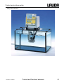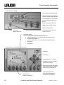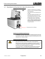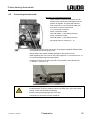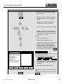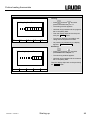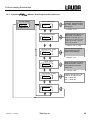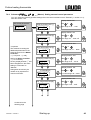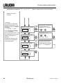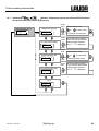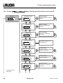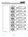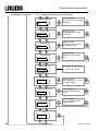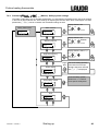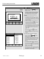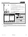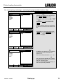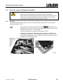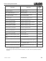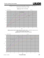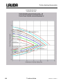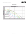
1
Operating Instructions PROLINE Thermostats with PowerAdapt System Heating thermostats P 5 (C), P 8 (C), P 12 (C), P 18 (C), P 26 (C), P 40 (C), P 50 (C) Calibration thermostat PJ 12 (C), PJL 12 (C) Clear view thermostats PV 15 (C), PVL 15 (C), PV 24 (C), PVL 24 (C), PV36 (C) Bridge thermostats PB (C), PBD (C) english YACE0071 / 07/11 b1 replaces 06/07, 01/05 from softwareversion of Control system (Master) 2.08 from softwareversion of Protection system (Master) 2.03 from softwareversion of Operating system (Command) 3.10 from softwareversion of Analogue interface 3.01 from softwareversion of RS232/485-module 3.03 from softwareversion of contact I/0 module 3.00 from softwareversion of solenoid valve 3.00 LAUDA DR. R. WOBSER GMBH & CO. KG P.O. Box 1251 97912 Lauda-Koenigshofen Germany Phone: 0049 9343 / 503-0 Fax: 0049 9343 / 503-222 E-Mail [email protected] Internet http://www.lauda.de Proline heating thermostats Prefixed safety notes Before operating the equipment please read carefully all the instructions and safety notes in Section 1. If you have any questions please phone us! Follow the instructions on setting up, operation etc. This is the only way to avoid incorrect operation of the equipment and to ensure full warranty protection. • Transport the equipment with care! • Equipment and its internal parts can be damaged: − by dropping, − by shock. • Equipment must only be operated by technically qualified personnel! • Never operate the equipment without the heat transfer liquid! • Do not start up the equipment if: − it is damaged or leaking, − cable (not only supply cable) is damaged. • Switch off the equipment and pull out the mains plug: − for servicing or repair, − moving the equipment! • Drain the bath before moving the equipment! • Do not carry out any technical changes on the device! (Ì Section 6). • Have the equipment serviced or repaired by properly qualified personnel only! The Operating Instructions include additional safety notes, which are identified by a triangle with an exclamation mark. Carefully read the instructions and follow them accurately! Disregarding the instructions may have serious consequences, such as damage to the equipment, damage to property or injury to personnel! We reserve the right to make technical alterations! YACE0071 / 7/26/2011 Prefixed safety notes 3 Proline heating thermostats Content Prefixed safety notes ....................................................................................................................................3 1 SAFETY INFORMATION.................................................................................................................................7 1.1 1.2 2 GENERAL SAFETY INFORMATION ...................................................................................................................7 OTHER SAFETY INFORMATION.......................................................................................................................8 BRIEF OPERATING INSTRUCTIONS ............................................................................................................9 2.1 2.2 MENU STRUCTURE: MASTER ......................................................................................................................10 MENU STRUCTURE: COMMAND REMOTE CONTROL .......................................................................................11 3 CONTROLS AND FUNCTIONAL ELEMENTS .............................................................................................12 4 DEVICE DESCRIPTION ................................................................................................................................17 4.1 4.2 4.3 4.4 4.5 4.6 4.7 4.8 4.9 ENVIRONMENTAL CONDITIONS ....................................................................................................................17 DEVICE TYPES ...........................................................................................................................................17 VARIOFLEX PUMP ......................................................................................................................................17 MATERIALS ...............................................................................................................................................18 TEMPERATURE DISPLAY, CONTROL AND SAFETY CIRCUIT..............................................................................18 PROGRAMMER AND RAMP FUNCTION ...........................................................................................................19 INTERFACES ..............................................................................................................................................19 INTERFACE MODULES (ACCESSORIES).........................................................................................................20 HEATER RATING AND POWER CONSUMPTION FROM THE MAINS .....................................................................20 5 UNPACKING..................................................................................................................................................21 6 PREPARATION .............................................................................................................................................22 6.1 6.2 6.3 6.4 6.5 7 ASSEMBLY AND SITTING .............................................................................................................................22 EXPANDING THE WORKING TEMPERATURE RANGE WITH EXTERNAL COOLING .................................................23 FILLING AND DRAINING ...............................................................................................................................24 HEAT TRANSFER LIQUIDS AND HOSES..........................................................................................................25 CONNECTING EXTERNAL LOADS ..................................................................................................................27 STARTING UP ...............................................................................................................................................28 7.1 MAINS CONNECTION ..................................................................................................................................28 7.2 SWITCHING ON ..........................................................................................................................................28 7.3 SWITCHING OFF / STANDBY ........................................................................................................................29 7.4 KEY FUNCTIONS ........................................................................................................................................30 7.4.1 General key functions and pilot lamps.............................................................................................30 7.4.2 Changing window information (Command remote control) .............................................................33 7.4.3 Locking the keyboard.......................................................................................................................34 7.5 MENU STRUCTURE: "MASTER"....................................................................................................................36 7.6 MENU STRUCTURE: “COMMAND REMOTE CONTROL” ....................................................................................37 7.6.1 Basic settings and branching to submenus (Master).......................................................................38 7.6.2 Submenu LMDkt (Master): Branching to further submenus.............................................................39 7.6.3 Submenu LMnet (Master): Configuration of modules ......................................................................40 7.6.4 Submenu LMDkt Æ O@pA- (Master): Configuration of device parameters ......................................41 7.6.5 Submenu LMDkt Æ O0c-- (Master): Setting internal control parameters .......................................42 7.6.6 Submenu LMDkt Æ O0c-- (Master): Setting external control parameters ......................................43 7.6.7 Submenu LMDkt Æ B@K-- (Master): Calibrating internal and external Pt100 temperature probe measuring chains (adjustment) ......................................................................................................................45 7.6.8 Submenu LMDkt Æ RgmY\ (Master): Displaying internal values of the thermostat ..........................46 7.6.9 Submenu LMnet Æ RDC-- (Master): Safety system settings ..........................................................49 7.7 IMPORTANT SETTINGS ................................................................................................................................50 7.7.1 Temperature setpoint setting ...........................................................................................................50 7.7.2 Displaying the actual external temperature .....................................................................................52 7.7.3 Setting pump power or standby .......................................................................................................53 4 Content YACE0071 / 7/26/2011 Proline heating thermostats 7.7.4 Activating external control............................................................................................................... 54 7.7.5 Current consumption from the mains.............................................................................................. 55 7.7.6 Setting the date and time (Command) ............................................................................................ 57 7.7.7 Display resolution setting (Command) ............................................................................................ 57 7.8 SPECIAL SETTINGS.................................................................................................................................... 58 7.8.1 Setpoint resolution .......................................................................................................................... 58 7.8.2 Defining the type of start mode ....................................................................................................... 58 7.8.3 Defining temperature limits ............................................................................................................. 60 7.8.4 Setpoint offset operating mode ....................................................................................................... 61 7.8.5 Restoring works settings................................................................................................................. 63 7.8.6 Setting the volume of the acoustic signals...................................................................................... 65 7.8.7 Entering the offset of the internal temperature probe ..................................................................... 66 7.8.8 Restoring the works setting of the internal temperature-probe offset............................................. 67 7.8.9 Entering the offset of the external temperature probe .................................................................... 68 7.8.10 Restoring the works setting of the external temperature-probe offset............................................ 69 7.9 GRAPHICAL DISPLAY OF TEMPERATURE MEASUREMENTS (COMMAND REMOTE CONTROL) ............................. 70 7.10 PROGRAMMER (PGM ONLY COMMAND REMOTE CONTROL) ..................................................................... 72 7.10.1 Program example............................................................................................................................ 72 7.10.2 Selecting and starting the program (Start, Hold, Stop) ................................................................... 74 7.10.3 Interrupting, continuing or terminating the program (Hold, Continue, Stop) ................................... 75 7.10.4 Creating or modifying a program (Edit)........................................................................................... 76 7.10.5 Defining the number of program loops (Loops) .............................................................................. 80 7.10.6 Viewing the program sequence as a graph (Graph)....................................................................... 80 7.10.7 Obtaining information on a program (Info) ...................................................................................... 81 7.11 RAMP FUNCTION ................................................................................................................................... 82 7.12 TIMER FUNCTION (COMMAND REMOTE CONTROL).................................................................................... 83 7.13 CONTROL PARAMETERS......................................................................................................................... 85 7.13.1 Internal control variable (integral measurement probe) .................................................................. 85 7.13.1.1 Proven settings for control parameters and pump (Internal control) ....................................... 86 7.13.2 External control variable (External measurement probe) ............................................................... 87 7.13.2.1 Proven settings for control parameters and pump (External control): ..................................... 88 7.13.2.2 Steps for setting the control parameters for external control................................................... 88 7.13.3 Internal and external control parameter sets .................................................................................. 90 7.13.4 Self Adaption (only Command remote control)............................................................................... 91 7.14 ALARMS, WARNINGS AND ERRORS......................................................................................................... 92 7.14.1 Overtemperature protection and checking...................................................................................... 93 7.14.2 Low-level alarm and low-level checking.......................................................................................... 94 7.14.3 High-level settings........................................................................................................................... 95 Master ........................................................................................................................................................ 96 7.14.4 High-level warning or alarm ............................................................................................................ 97 7.14.5 Pump-motor supervision: Overload or blockage............................................................................. 98 7.14.6 Pump-motor supervision: Dry running ............................................................................................ 98 7.14.7 Fault list “Alarms and Warnings”..................................................................................................... 99 7.15 RS 232 / RS 485 INTERFACE (ONLY COMMAND OR MODULE) ............................................................... 102 7.15.1 Connecting cables and interface test RS 232............................................................................... 102 7.15.2 Protocol RS 232 ............................................................................................................................ 102 7.15.3 Connecting cable RS 485 ............................................................................................................. 103 7.15.4 Protocol RS 485 ............................................................................................................................ 103 7.15.5 Write commands (Data commands to the thermostat) ................................................................. 104 7.15.6 Read commands (Data requested from the thermostat) .............................................................. 105 7.15.7 Error messages............................................................................................................................. 107 7.15.8 Driver software for LABVIEW® ..................................................................................................... 107 8 INTERFACE MODULES ............................................................................................................................. 108 8.1 INSTALLING MODULES ............................................................................................................................. 108 8.2 MENU STRUCTURE FOR ALL MODULES (ONLY COMMAND REMOTE CONTROL).............................................. 109 8.3 SERIAL INTERFACES RS 232/485 ............................................................................................................ 110 8.3.1 Menu structure for RS 232/485 interface module (Master)........................................................... 110 YACE0071 / 7/26/2011 Content 5 Proline heating thermostats 8.4 ANALOGUE MODULE .................................................................................................................................111 8.4.1 Menu structure Analogue module (Master) ...................................................................................113 8.5 CONTACT MODULE ...................................................................................................................................114 8.5.1 Contact module LRZ 915 with three inputs and three outputs ......................................................114 8.5.2 Namur-Contact module LRZ 914 with only one input and one output...........................................115 8.5.3 Menu structure contact module (Master) .......................................................................................116 9 MAINTENANCE ...........................................................................................................................................117 9.1 CLEANING ...............................................................................................................................................117 9.2 DEVICE STATUS .......................................................................................................................................117 9.2.1 Interrogating the device type..........................................................................................................117 9.2.2 Software Version............................................................................................................................117 9.2.3 Serial numbers...............................................................................................................................117 9.2.4 Device data ....................................................................................................................................118 9.2.5 Fault memory (Command) .............................................................................................................118 9.3 SERVICING, REPAIR AND DISPOSAL INFORMATION ......................................................................................119 9.3.1 Servicing ........................................................................................................................................119 9.3.2 Servicing intervals according to VDI 3033 .....................................................................................120 9.3.3 Inspecting the heat transfer liquid..................................................................................................120 9.3.4 Repair information..........................................................................................................................120 9.3.5 Disposal information ......................................................................................................................121 9.3.6 Disposal of the packaging..............................................................................................................121 9.4 ORDERING REPLACEMENT PARTS / LAUDA SERVICE.................................................................................121 10 ACCESSORIES........................................................................................................................................122 11 TECHNICAL DATA AND DIAGRAMMS .................................................................................................124 12 INDEX .......................................................................................................................................................130 Explanation of signs : Ì 6 Caution: This sign is used where there may be injury to personnel if a recommendation is not followed accurately or is disregarded. Note: Here special attention is drawn to some aspect. May include reference to danger. Reference Refers to other information in different sections. Content YACE0071 / 7/26/2011 Proline heating thermostats 1 Safety information 1.1 General safety information A laboratory thermostat heats and circulates liquids according to specified parameters. This involves hazards due to high temperatures, fire and general hazards due to the application of electrical energy. The user is largely protected by the application of relevant standards. Further hazard sourcesmay arise due to the type of tempering medium, e.g. by exceeding or undercutting certain temperature thresholds or by the breakage of the container and reaction with the heat transfer liquid. It is not possible to consider all eventualities. They remain largely subject to the judgment and responsibility of the operator. The equipment may only be used as prescribed and as described in these operating instructions. This includes operation by instructed specialist personnel. The equipment is not rated for use under medical conditions according to DIN EN 60601-1 or IEC 601-1. Classes in the EMC standard DIN EN 61326-1. Class A: Operation only on networks without connected domestic areas. Class B: Equipment for operation on networks with connected domestic areas. Class B*: Equipment fulfils Class B when a house connection > 100 A is involved. With unfavourable network conditions disturbing voltage variations may otherwise occur. EMC standard DIN EN 61326-1 (corresponds to VDE 0843-20-1) Devices for Europe Class B Devices for Canada and the USA Class A Usage restriction For the EMC standard DIN EN 61326-1: Devices in Class A are only to be operated on electrical supply networks without connected domestic areas. Instructions for Class A digital devices, USA: “This equipment has been tested and found to comply with the limits for Class A digital device, pursuant to Part 15 of the FCC (Federal Communication Commission) Rules. These limits are designed to provide reasonable protection against harmful interference when the equipment is operated in a commercial environment. This equipment generates, uses, and can radiate radio frequency energy and, if not installed and used in accordance with the instruction manual, may cause harmful interference to radio communications. Operation of this equipment in a residential area is likely to cause harmful interference in which case the user will be required to correct the interference at his own expense.” “This device complies with Part 15 of the FCC (Federal Communication Commission) Rules. Operation is subject to the following two conditions: (1) This device may not cause harmful interference, and (2) this device must accept any interference received, including interference that may cause undesired operation.” Instructions for Class A digital devices, Canada: “This Class A digital apparatus complies with Canadian ICES-003” (ICES = Interference Causing Equipment Standards). « Cet appareil numérique de la Classe A est conforme à la norme NMB-003 du Canada ». YACE0071 / 7/26/2011 Safety information 7 Proline heating thermostats 1.2 Other safety information • Only connect equipment to PE grounded mains sockets. • At higher operating temperatures, parts of the bath cover can reach surface temperatures exceeding 70°C. Be careful when touching it Æ Risk of burning! • Use suitable hoses (Ì Section 6.4). • Secure hose against slippage with the aid of hose clips. Avoid kinks in the hoses. • Check hoses from time to time for any possible material fatigue. • Thermal medium hoses and other hot parts must not come into contact with the mains cable. • With the use of thermostats as circulating thermostats hot liquid can be emitted when the hose breaks, presenting a hazard to persons and material. • If no external load is connected, the pump outflow must be closed (use screw plugs) and the bypass valve must be set to "internal" (Ì 4.3). • Take into account the thermal expansion of the heat transfer oils with increasing bath temperature. • Depending on the heat transfer liquid used and the type of operation, toxic vapours can arise. Ensure suitable extraction. • When changing the heat transfer liquid from water to a thermal transfer medium for temperatures above 100 °C, carefully remove all water residues, including from the hoses and loads. When doing this, also open the screw plugs (HKN 065) (Ì 3) of the pump outputs and inputs and blow compressed air through all the pump outputs and inputs. With higher temperature there is the risk of burning due to delay in boiling! • Withdraw the mains plug before cleaning, maintenance or moving the thermostat. • Repairs in the control section must only be carried out by specialist personnel. • Figures of temperature constancy and display accuracy apply under normal conditions according to DIN 12876. Electromagnetic high frequency fields may in special cases lead to unfavourable values. Safety is not impaired. • The following action may start the thermostat unintentionally from the standby mode: Previously activated timer mode (Ì 7.12), "Start" command via interfaces (Ì 8). EC conformity The device conforms to the relevant fundamental requirements for safety and health of the following listed directives: • Low Voltage Directive 2006/95/EC • EMC Directive 2004/108/EC LAUDA DR. R. WOBSER GMBH & CO. KG Postfach 1251 97912 Lauda-Königshofen Germany 8 Safety information YACE0071 / 7/26/2011 Proline heating thermostats 2 Brief operating instructions These brief instructions shall give you the possibility to operate the unit quickly. For safe operation of the unit, it is absolutely necessary to read carefully all the instructions and safety notes! 1. Assemble unit and add items as appropriate (Ì 6.1). Take care of the hose tubing connections (Ì 6.4 and 6.5). 2. Fill the unit with corresponding heat transfer liquid (Ì 6.4). The units are designed for operation with non-flammable and flammable liquids to DIN EN 61010-2-010. Æ Take care of the level of the heat transfer liquid! (Ì 6.3). 3. Compare the information on the rating label with the supply details. 4. Connect the unit only to a socket with a protective earth (PE) connection. 5. Check whether the main fuse-switch at the back is in the "On = –" position. 6. Switch the unit on with the switch at the front. 7. With set the overtemperature cut-off point to a value clearly above room temperature (Ì 7.14.1). 8. Now you see the current bath temperature in the display, e.g.: Bath-temperature /1%21 °C If instead, a warning or error message is displayed, then refer to Section 7.13.3. YACE0071 / 7/26/2011 Brief operating instructions 9 Proline heating thermostats 2.1 Menu structure: Master Display flashes. Set setpoint Setpoint Bath temperature 1%21 °C External temperature 1%/1 °C EXT RDr or . Display is accepted afer 4 sec. or proceed immediately with the key: Pump power.1-8/Standby.0 Os with °C 7 °C ⇒ Section 7.7.1 Display flashes. Set value with Control Intern / Extern Bml 0 °C Further settings LMDkt °C or . Display is accepted afer 4 sec. or proceed immediately with the key: ⇒ Section 7.7.3 ⇒ Section 7.7.4 Control parameters, setpoint resolution, setpoint-source input, calibration, etc. ⇒ Section 7.6.2 Configure modules LMnet °C Protection system, Command, cooling system, analog and RS232 digital module, etc. ⇒ Section 7.6.3 End Dlc °C To reset the unit to the factory default state which enables basic operation with internal control, there is Æ Æ the default function in the menu (Ì 7.6.4). LMDls O@p@ cDE 10 Brief operating instructions YACE0071 / 7/26/2011 Proline heating thermostats 2.2 Menu structure: Command remote control Menu Pump Level Calibration Works settings Resolution Device status Display data Basic settings Overlevel handling Set time Set data Timer 1 Timer 2 Format of data Pump Settings Clock Graph Programmer 1 Interfaces Control Limits Settings Program 1 Program 2 Program 3 Program 4 Program 5 Ramp function 1 Serial Command 2 serial Master / Profibus Analogue interfaces Switching contact Cooling valve Refill valve Shut off unit (Ì 8.2) 2 no menu in Command internal external Pt100 ext. Analog interface ext. seri. RS 232/485 Control variable Control parameters Setpoint offset T il (min) T ih (max) YACE0071 / 7/26/2011 intern Pt100 extern Pt100 Calibration Default All Modules Master Command Contact Other connected modules all default Device type Software Version Serial numbers Device data Error store Basic window Standard window Super window Display Sounds Language Master mode Autostart Current consumpt. DLK connect Mode Displayed value Legend Sample Time Time axis Time axis Temp.scale Temp.limits All default Only control par. int. Only control par. ext. Only miscellaneous Show Edit Default Brightness Contrast Alarm Warning English Deutsch Français Español no yes None Warnig Warn. + Heater off Alarm Start / Stop Hold / Continue Modify Erase Show chart Status Edit Loops Graph Info Xp Tn Tv (auto) Td (auto) Status Temp. Change Time Time unit Kpe Tne Tve (auto) Tde (auto) Xpf Prop_E (a) Modus Baudrate RS485 adress Control parameters Control para. sets Tv manual/auto Self Adaption Correction limitation Offset source Setpoint offset Brief operating instructions Automatic Manual Settings off external Pt100 RS 232 11 Proline heating thermostats 3 Controls and functional elements with Command remote control (see page 14) Master control panel (see page 14) Mains switch Bypass-valve (see illustration on next page) Pump connection at side: Suction nozzle (return to bath). Pump outflow, pressure output. (Refer to housing for lavbel). Bath cover Recessed grip 12 Controls and functional elements YACE0071 / 7/26/2011 Proline heating thermostats Command remote control (see page 14) Cover for the two module slots Connection socket 10S für the external Pt100 temperature probe Connection socket 70S (CAN 1 and 2) for bus suitable for unit and to which the refrigerating lower section and Command Console are connected Main fuse-switch Connection socket 51H for through-flow cooler DLK (accessary) Mains connecting lead Rear pump connection: Suction nozzle (return to bath) Pumpe outflow (pressure output). Air intake to electronic head Cooling coil: Cooling water outlet connection M14 x 1.5 with adapted pump nipple. Cooling coil: Cooling water inlet connection with adapted accessories: Cooling valve LCZ 9662 Bypass valve (in “external” position) Side pump connection: Pumpe outflow (closed off with screw plug). Refer to housing for label Side pump connection: Suction nozzle (return to bath) (closed off with screw plug). Refer to housing for label YACE0071 / 7/26/2011 Controls and functional elements 13 Proline heating thermostats Proline P 50 C Clear view thermostat PVL 24 14 Controls and functional elements YACE0071 / 7/26/2011 Proline heating thermostats Bridge thermostat PB C YACE0071 / 7/26/2011 Controls and functional elements 15 Proline heating thermostats Control element: “Master” Error signal (red LED blinking). Bath controlled by external temperature source (green LED lits). EXT The temperature of an external source is displayed (EXT is lit green). Cooler active (blue LED is lit). Heater active (yellow LED lit). Select and Enter keys. Overtemperature set point to check or set Tmax . Mains ON (green LED is lit). Graphical display, here in the standard window displaying the values: • Actual temperature Tint of internal bath temperature probe • Setpoint temperature Tset • Actual temperature Text of external bath tempeature probe • Bath level • Pump level. Control element: “Command remote control” Enter key Cursor key Decimal point or “-” symbol Escape key, to quit a window without any changes. Standby key, brings the thermostat into the idle mode. Heater and pump are switched off. RS232-socket (hidden on the back). 16 Controls and functional elements Five Softkey duo-keys, their associated functions are shown in the display. YACE0071 / 7/26/2011 Proline heating thermostats 4 Device description 4.1 Environmental conditions The operation of the thermostats is only allowed under the following conditions as specified in DIN EN 61010-2-010:2003 and DIN EN 61010-1:2001: − Indoor use only. − Elevation up to 2000 m above sea level. − Foundation must be dense, even, non-slippery and non-flammable. − Keep clear distance to walls (Ì 6.1). − Ambient temperatures range (Ì 11). Use only within this range for an undisturbed operation. − Mains supply voltage fluctuations (Ì 11). − Relative humidity (Ì 11). − Transient over voltage according to Installation Categories (Over voltage Categories) II. − Pollution degree: 2. 4.2 Device types The type designation of the Proline heating thermostats always begins with P for Proline. The meaning of the following letters is: V for clear-view thermostats respectively VL with insulation for an extended temperature range, J for calibration thermostats respectively JL with insulation for an extended temperature range. The following numbers are equal to the bath volume in liters. The models PB for min. 200 mm bath depths and PBD for min. 320 mm bath depths can be used as bridge thermostats. Units with Command remote control version are signed with a C as last letter. Examples: P 5 C is a Bath thermostat with 5-liter Bad and Command remote control. PVL 15 is a clear view thermostat with 15-liter bath and operating temperature up to -60 °C (with LAUDA add-on cooler). PJ 12 C is a calibration thermostat with 12-liter bath and Command remote control. PBD C is a bridge thermostat with big immersion depth and Command remote control. 4.3 VarioFlex pump All units are fitted with a VarioFlex pump with an 8-stage variable drive. The pump power can therefore be optimally matched to the relevant task: High pump pressure when, for example, long hoses pass to external loads or circulation is to be provided for a large bath. Low pressure when the heat input into the bath must be low. With heating thermostats P 5, P 8, P 18 and P 26 the VarioFlex pump enables as a delivery/suction pump, the very effective supply of pressure-sensitive glass reactors which have a minimum permissible pressure rating. The thermostats P 12, P 12 C, PJ 12 and PJ 12 C with extreme bath depth and the bridge thermostats PBD are equipped with a very effective pressure pump as all clear view thermostats (PV 15, PVL 15, PV 24, PVL 24, PV 36). Furthermore, open vessels can be operated when a constant level controller (accessory LCZ 0660) is used (except P 12 (C) and PV/ PVL (C)). YACE0071 / 7/26/2011 Unit description 17 Proline heating thermostats At the right-hand side and at the back of the unit outflow and inflow nozzles are fitted for external loads. This means that up to two external loads can be directly connected without a distributor. Connections which are not required must be closed off with the supplied caps and union nuts. A bypass valve can subdivide the total volume flow variably between the bath (internally) and the connected load (externally). Consequently, no "pump short circuit" is needed. If no load is connected to the pump connector, the bypass valve must be set to the “internal” position for the best bath circulation. In the heating range the VarioFlex pump operates up to viscosity values of 150 mm²/s. In the closedloop control mode 50 mm²/s should not be exceeded. The temperature control is the best with 30 mm²/s and lower viscosity. With small bath thermostats (e.g. P 8) power level 3 to 6 is practicable. For operation as a circulating thermostat with an external load, a higher power level is practicable to maintain the temperature difference low, among other things also with higher temperatures in conjunction with oils as heat transfer liquids. The pump connections on the unit are fitted with M16 x 1 threads. The pump outflows of the VarioFlex pump can be closed off without any impairment to the pump. Here, the "internal" setting of the bypass controller is recommended. Pump characteristics (Ì Section 11). 4.4 Materials All parts being exposed to with the heat transfer liquid are made of high quality material appropriate to the operating temperature. Non-rusting stainless steel and high quality temperature-resistant, primarily solvent-resistant plastics are used. 4.5 Temperature display, control and safety circuit In the Master Version, the units are equipped with a 5-character green LED display, which is used for the display of the measurements and settings, as well as the operating status. The entry of setpoints and other settings occurs under menu guidance via four keys. The extra features of the Command Version include a removable console with a backlit graphical display. The entry of the setpoint and other settings occurs under menu guidance via situation-dependent cursor keys and soft keys. A Pt100 temperature probe acquires the outflow temperature in the bath. A high-resolution A/ D converter processes the measurement. Further measurement conditioning occurs using a special control algorithm for controlling the heater actuator, which has a low reactive effect on the mains. An external Pt100 can be connected via a socket (10S) for the acquisition of an external temperature. This value can be displayed and, if required, used as the controlled variable with external control (Master) switched on. In this way the system controls the external measurement and not the outflow temperature (Ì 7.7.4). The safety system conforms to DIN EN 61010-2-010. The SelfCheck Assistant monitors about 50 unit parameters, A dual-channel system is used in which two microcontrollers monitor one another. Along with the bath temperature measurement and control probes, there are also two safety temperature probes (Pt100) for the safety circuit for the overtemperature cut-off and for monitoring the bath temperature probe. The overtemperature cut-off point is displayed on pressing the key on the Master. Changing the overtemperature cut-off point: (Ì 7.2) (Switching on) on page 28. The bath level is acquired by the SelfCheck Assistant in 8 stages. A permanent display is provided only 18 Unit description YACE0071 / 7/26/2011 Proline heating thermostats with the Command Version. At the Master version it is showed in the submenu RgmY[ . If the minimum level is undercut, the pump and heater are switched off. The reaction of the thermostat in case of overfill can be set to simply display a warning, to display a warning and switch off the heater or to switch off the unit completely with pump and heater. When the level is too low, with overtemperature, or with other alarms the SelfCheck Assistant switches the heater off on all poles. The pump is also switched off. This switch-off under fault conditions is retained, i.e. after the fault is rectified, the fault must be reset (released) on the Master operating panel with the key. Other unit functions are described in the appropriate sections and in Section 7. (Starting up). 4.6 Programmer and ramp function Master Version: No programmer provided. Command Version: The units are equipped with a programmer function, which enables five temperature/ time programs to be saved. Each program consists of a number of temperature/ time segments. These also include details of how often the program is to be executed. Up to 150 segments can be distributed amongst the five programs. With the ramp function, a rate of change can be directly entered in °C per unit time. (Ì 7.10). 4.7 Interfaces Master Version: In the basic version the Master unit is equipped with the following sockets at the back of the control head: • For the connection of an external Pt100 temperature sensor (10S). • Two sockets (70S) for the connection of components via the LAUDA equipment bus (cooling section, Command remote control, external solenoid valve, etc.). Command Version: The Command remote control is equipped as standard with the following sockets: • For the connection of an external Pt100 temperature probe (10S). • Two sockets (70S) for the connection of components via the LAUDA equipment bus (cooling section, Command remote control, external solenoid valve, etc.) • An RS 232/485 interface (65S) at the back of the Command remote control. YACE0071 / 7/26/2011 Unit description 19 Proline heating thermostats 4.8 Interface modules (accessories) The Master and Command can be supplemented with further interface modules, which are simply inserted into two module slots (see Section 3) at the back of the control head. The following modules are currently available: 1. RS 232/485 Interface Module (Order No. LRZ 913) with 9-pole SUB-D socket. Electrically isolated through optocouplers. Command set largely compatible with the Eco, Ecoline, Integral XT and Integral T Series. The RS 232 interface can be directly connected to the PC with a cable wired 1:1 straight through (Order No. EKS 037). Further details can be found in section 8.3. 2. Analog Module (Order No. LRZ 912) with two inputs and two outputs on 6-pole DIN socket. The inputs and outputs can be set independently as 4...20 mA, 0...20 mA or 0...10 V interface. Further details can be found in section 8.4. 3. Contact Module (Order No. LRZ 915) on 15-pole SUB-D socket. With three relay contact outputs (changeover, max. 30 V/ 0.2A) and three binary inputs for control via external voltage-free contacts. Plug 15-pole, Order No. EQM 030 and plug case Order No. EQG 017. Further details can be found in section 8.5. 4. Contact Module (Order No. LRZ 914) with connector to NAMUR NE28. Functionality as LRZ 915, but only one output and one input on each of two DIN sockets. Coupling socket 3-pole, LAUDA Order No. EQD 047 and coupling plug 3-pole, LAUDA Order No. EQS 048. Further details can be found in section 8.5. 5. Profibus Module (Order No. LRZ 917). Further details can be found in the operating instructions YAAE0020. 4.9 Heater rating and power consumption from the mains The Proline Low-Temperature Thermostats have an extraordinarily high heater rating of 3.5 kW maximum. If your mains fuse is rated below 16 A, the current consumption can be reduced in steps from 16 A to 10 A (Ì 7.7.5). The maximum heater rating of 3.5 kW is then, of course, also reduced accordingly. 20 Unit description YACE0071 / 7/26/2011 Proline heating thermostats 5 Unpacking Keep your original packing of your thermostat for later transport. After unpacking, firstly check the device and accessories for any damage in transit. If, contrary to expectations, there is visible damage to the unit, the shippers or the postal service must be immediately informed, so that an investigation can be made. Please also inform the LAUDA Service Constant Temperature Equipment (Contact Ì 9.4). Standard Accessories: Catalogue number Quantity Designation YACE0071 1x Operating instructions (this document) for all Proline heating thermostats, clear-view thermostats and calibration thermostats Bath cover for heating thermostats except clear-view thermostats and except bridge thermostats HDQ 107 1x Bath cover for Proline P 5 HDQ 108 1x Bath cover for Proline P 8 and P 12 HDQ 109 1x Bath cover for Proline P 18 and P 26 HDQ 110 1x Bath cover for Proline P 26 HDR 028 1x Bath cover for Proline PJ(L) 12 calibration thermostats HKO 026 (UD 413) 2x Hose olive Ø 13mm for all heating thermostats HKM 032 4x Union nuts for olives Ø 13mm (M16 x 1) already adapted for heating thermostats HKN 065 4x Screw plugs (for M16 x 1) already adapted for heating thermostats HKO 009 (UD 415) 2x Tubing nipple Ø 11mm for cooling coil of heating and clear-view thermostats HKM 045 (UD 415) 2x Union nuts for olives Ø 10mm (M14 x 1,5) for cooling coil of heating and clear-view thermostats Warning label "Hot“ EZB 260 YACE0071 / 7/26/2011 1x for all heating thermostats Unpacking 21 Proline heating thermostats 6 Preparation 6.1 Assembly and sitting − Site the unit on a flat surface − The unit must not be put into operation if its temperature during storage or transport has dropped below the dew point. Wait for about one hour. − Do not cover the ventilation openings at the back of the control head. − When used as a bath thermostat put the bypass valve in “internal” position (without “external load”) (Ì 3). Operation with external loads (Circulating thermostat) continue at (Ì 6.5). − Check whether the pump connectors at the side and back are fitted with sealing caps (Ì Section 3) or that hoses are fitted for external loads. − With bath temperatures over 70 °C the supplied self-adhesive label should be applied on the bath at an easily visible point. − Do not carry out technical changes on the device! 22 The unit can safely operated up to an ambient temperature of 40 °C. Preparation YACE0071 / 7/26/2011 Proline heating thermostats 6.2 Expanding the working temperature range with external cooling Operation with internal cooling coil − A different cooling source, for example tap water, can be connected as standard to the cooling coil. − Tubing with 10 mm inner diameter must be used. − The lowest operating temperature of the thermostat without external consumer can be reduced to a value of 5 °C above the temperature of the cooling liquid. − In combination with the cooling liquid valve LCZ 9662 (controlled by Proline by means of LiBus) as optional accessory the cooling water will only be opened if cooling is required. Cooling liquid valve LCZ 9662 Operation with a LAUDA through-flow cooler − A LAUDA DLK 10, DLK 25, DLK 45 or DLK 45 LiBus through-flow cooler can be connected to the pump connection points. The through-flow cooler is built into the return line (suction tubing) from the load to the thermostat and is only switched in when cooling is needed. Operation with high temperature cooler − For bath temperatures above 155 °C it is not allowed to cool with water together with the simple cooling coil (water vapor Æ risk of explosion). − Especially for the Proline there is a controlled high temperature cooler for fast and time saving cooling with bath temperatures up to 300 °C (accessory LCZ 9663). Due to its special construction it is possible to cool with water without the risk of producing dangerous water vapor. − The high temperature cooler shall not be connected to the cooling coil connections. It must be connected to the external pump connections. YACE0071 / 7/26/2011 Preparation 23 Proline heating thermostats 6.3 Filling and draining Filling − Close the drain cock! − Carefully remove all residues of the previous heat transfer liquid (blow dry and remove screw plugs!). − Maximum filling level is up to 10 mm below the top edge of the bath. Overfilling leads to the display of the warning (Ì Section 7.14.4). VW0/2 − Best operation is with a level 20-80 mm below the top edge of the bath. − Low-level cut-off occurs at about 95 mm (at P 12 and PBD approx. 215 mm) below the top edge of the bath. − The units are designed for use with non-flammable and flammable liquids to DIN EN 61010-2-010. Flammable liquids must not be used higher than 25 °C below the fire point (Ì Section 6.4). − When using thermal transfer oils note that they expand on heating (approx. 10 % per 100 °C). − With enclosed external loads, the overall expansion takes place in the bath. − Ensure that with the connection of an external load, the liquid level does not drop impermissibly due to filling the load Top up with heat transfer liquid if necessary. − Set the upper and lower temperature limits (Ì 7.8.3) in accordance with the limits of the heat transfer liquid in use. Draining − Switch off the thermostat, withdraw the mains plug! − Let out the heat transfer liquid through the drain cock; fit a hose when doing this. − The drain cock is placed on the back of the heating thermostats. Drain cock Completely drain the bath, external consumers, accessories and hose connections and flush or clean them (e.g. with new heat transfer liquid). − Follow the regulations for the disposal of used heat transfer liquid. Do not drain heat transfer liquid when hot or at bath temperatures below 0 °C! 24 Preparation YACE0071 / 7/26/2011 Proline heating thermostats 6.4 Heat transfer liquids and hoses Approved heat transfer liquids LAUDA designation Temperature range Chemical designation from °C to °C Viscosity (kin)) Viscosity (kin) at temperature Fire point mm²/s at 20°C mm²/s °C Packing drum Order number 5L 10 L 20 L Aqua 90 5...90 Decalcified water 1 -- -- LZB 120 LZB 220 LZB 320 Kryo 30 -30...90 Monoethyleneglycol/water 4 50 at -25 °C -- LZB 109 LZB 209 LZB 309 Kryo 20 -20...180 Silicone oil 11 28 at -20 °C > 230 LZB 116 LZB 216 LZB 316 Therm 160 60...160 Polyalkyleneglycol 141 28 at 60 °C > 273 LZB 106 LZB 206 LZB 306 Therm 180 0...180 Silicone oil 23 36 at 0 °C > 288 LZB 114 LZB 214 LZB 314 Therm 200 60...200 Silicone oil 54 28 at 60 °C 7 362 LZB 117 LZB 217 LZB 317 Therm 240 50...240 Silicone oil 125 45 at 50 °C 7 378 LZB 122 LZB 222 LZB 322 Ultra 300 80...300 Silicone oil 170 39 at 80 °C > 400 LZB 108 LZB 208 LZB 308 Ultra 350 30...200 syntheti heat transfer liquid 47 28 at 30 °C 7 240 LZB 107 LZB 207 LZB 307 { At higher temperatures vaporisation losses occur. In this case use a bath cover. Only use distilled water or fully demineralized high purity water after adding 0.1 g of soda (Na2CO3 sodium carbonate) per liter of water. Otherwise there is the risk of corrosion! Water content falls with longer operation at high temperatures. The mixture becomes flammable (flash point 128 °C). Check the mixture ratio with a hydrometer. Do not use in conjunction with EPDM hose! − With the selection of the heat transfer liquid it should be noted that impairment of the properties is to be expected at the lower limit of the temperature range due to increasing viscosity. Therefore, only make maximum use of temperature ranges when essential. − Application ranges of heat transfer liquids and hoses are general figures, which may be restricted by the operating temperature range of the units. With silicone rubber, silicone oils lead to substantial swelling. Never use silicone oil with silicone hoses! Safety data sheets can be ordered if required! YACE0071 / 7/26/2011 Preparation 25 Proline heating thermostats Hoses Approved elastomer hoses Hose type Internal width Ø mm Temperature range °C Field of application Catalogue number EPDM hose uninsulated 9 10...120 For all LAUDA heat transfer liquids except Ultra 350 and mineral oils RKJ 111 EPDM hose uninsulated 12 10...120 For all LAUDA heat transfer liquids except Ultra 350 and mineral oils RKJ 112 EPDM hose insulated 12 External Ø approx. 35mm -60...120 For all LAUDA heat transfer liquids except Ultra 350 and mineral oils LZS 021 Silicone hose uninsulated 11 -30...100 Water Water/ glycol mixture RKJ 059 Silicone hose insulated 11 External Ø approx. 35mm -60...100 Water Water/ glycol mixture LZS 007 Viton 11 10...200 For all LAUDA heat transfer liquids RKJ 091 Viton insulated 8.5 External Ø approx. 30mm -20...150 For all LAUDA heat transfer liquids LZS 017 Viton insulated 11 External Ø approx. 32mm -20...150 For all LAUDA heat transfer liquids LZS 018 − EPDM hose is not suitable for Ultra 350 and not suitable for mineral oils! − With silicone rubber, silicone oils lead to substantial swelling Æ never use silicone oil with silicone hoses! − Secure hoses against slippage with hose clips. Approved metal hoses in non-rusting stainless steel with union nut M 16x1, internal width 10 mm Length cm Temperature range °C Field of application Catalogue number MC 50 50 10…400 With simple insulation, for all LAUDA heat transfer liquids LZM 040 MC 100 100 10…400 " LZM 041 MC 150 150 10…400 " LZM 042 MC 200 200 10…400 " LZM 043 MK 50 50 -90…150 With foam insulation for refrigeration range, for all LAUDA heat transfer liquids LZM 052 MK 100 100 -90…150 " LZM 053 MK 150 150 -90…150 " LZM 054 MK 200 200 -90…150 " LZM 055 Type 26 Preparation YACE0071 / 7/26/2011 Proline heating thermostats 6.5 Connecting external loads Operation as circulating thermostat − When used as circulation thermostat, care for shortest hose connections with largest inner diameter as possible. This gives the best flow. − Push hose with 11-12 mm internal width onto hose olive or connect metal hoses (Ì 6.4) to pump connectors. − Pump connectors at side: Inlet and outflow Ì see labeling housing. − Pump connectors at back Inlet and outflow Ì see labeling housing. − Set bypass valve to “external” (Ì 3). − If cross-sectional area of tube is too low Æ temperature gradient between bath and external load due to low flow rate. − Always ensure the largest possible passages in the external circuit! − When tightening the union nuts on the pump nipple AF 19, use a wrench AF 14 to counter the tightening torque (see figure). − If external control is to be used, provide a Pt100 probe in the external load (Ì Section 7.7.2 and 7.7.4). − With loads at a higher position and with stationary pump and ingress of air into the thermostatic circuit, the external volume can drain away, even with closed circuits Æ Risk of thermostat overflowing! − Secure hoses against slippage with hose clips! − Unused pump connectors must be closed off. YACE0071 / 7/26/2011 Preparation 27 Proline heating thermostats 7 Starting up 7.1 Mains connection Compare the rating on the name-plate (back of control head) with the mains voltage. − Connect unit only to sockets with a protective earth conductor (PE). − No liability is accepted for incorrect mains connections! − Ensure that pump connectors without external loads are closed off. − Ensure that the unit is filled according to Section 6.3. 7.2 Switching on Check whether the main fuse switch at the back is in the ‘On = –’ position. Switch on the mains switch : − The green LED for ‘Mains ON’ is lit, − an acoustic signal is emitted for about 1 s. 1s Self-test − The unit starts its self-test. All display segments and symbols appear for about 1 second. 77((( °C EXT Bath temperature /1%21 °C − The momentary bath temperature is displayed, − the pump starts provided ‘Standby’ or ‘Manual start’ (Ì Section 7.8.2) has not been programmed, − all values are accepted which were active before switch-off. Check or set overtemperature cut-off point: Overtemperatu. cut-off. 8/ °C − The switching point is shown in the LED display on pressing the key . − Change overtemperature cut-off (Ì Section 7.14.1) Overtemperature protection and checking on page 93. 28 − If necessary, top up heat transfer liquid which has been pumped out by filling the external load. Starting up YACE0071 / 7/26/2011 Proline heating thermostats − Display for little liquid. Level alarm KDTDK °C KDTDK − Red LED (low level) appears when the bath has too above the fault triangle flashes. − Find cause of fault and, where necessary, top up missing heat transfer liquid (Ì Section 6.4). − Press the Enter key. − Also press the key if unit has been switched off in the fault state. − No release is possible on Command remote control! Command remote control Language − If the Command remote control is being switched on for the first time, the illustrated window appears automatically, enabling you to select the dialog language with the appropriate soft key. English Deutsch Français Español Display Sounds Master Sounds Command Language Master-Mode Autostart Current Consumpt. DLK connected Pump 7.3 Menu − The dialog language also can be changed later via Æ Settings Æ Basic settings Æ Language . English Deutsch Français Español End − Mark the required language with or . − Confirm the selection with Tset . Tfix Switching off / standby Switching off: Set mains switch to position 0. Standby operation: Use the key on the Command remote control. The pump and heater are switched off. The operating display remains active, so that the device status is visible and adjustments can be made. YACE0071 / 7/26/2011 Starting up 29 Proline heating thermostats The timer continues to run. Stop as required with Pause (Ì 7.12). 7.4 Key functions Your Proline Thermostat is easy to operate. 7.4.1 General key functions and pilot lamps Master Enter key: − From the actual-value display at the main menu level, − activates input, display flashes, − saves input, display ceases to flash and menu point is left, − press for approx. 3 s: Exit function and returns to bath temperature display. − Paging with keys is possible within the relevant level, or setting of numerical values or Speeds up entry by moving the counting position to the left: a) Keys are pressed and held down or b) One of the two keys is pressed and held down, followed immediately by brief pressing of the other key. Moves counting position to the right: − Switching one place to the right occurs by briefly (1 s) releasing the key, followed by another pressing of the key. Useful additional information: − 2 dots in the Master display indicate that a submenu follows. --- °C − 3 dots in the display indicate that a submenu for a module (interface...) or a component (thermostat, Command remote control ....) follows. Module/component-specific possible settings are only displayed when the hardware is connected. − The following always applies: After termination of the relevant settings, they are accepted automatically after approx. 4 s or − the setting is accepted immediately with the Enter key. and − Fault signal. Flashing red Alarm LED and acoustic signal. − An acoustic signal can only sound when it has not been intentionally deactivated! (Ì 7.8.6) − The bath control occurs via the external temperature probe when the green LED is lit. − Heating is active when the yellow LED is lit. − Cooling is active. When the setpoint temperature is lowered, it makes take up to one minute before the blue LED is lit. EXT 30 − The temperature of the external probe is displayed. Starting up YACE0071 / 7/26/2011 Proline heating thermostats Command − Enter key ("Confirm selection") and go back one level. − Soft key function to confirm a selection or input and to return to the main display window. End − Escape key to quit a window without changes and to go back one level. − Cursor keys for Up, Down, Left and Right. − Standby activation (pump and heater are deactivated when the yellow LED is lit). However, the Timer goes on! See safety information on (Ì 7.7.3). + Duo key: − Top: Decimal-point key. − Bottom: Key for arithmetical sign. − Soft keys: 5 duo-keys which each have the function shown in display above them. Soft-key entries are shown framed in the operating instructions. Example: You would like to change the setpoint temperature, then press the duo-key under Tset . Brightness Brightness Display Contrast Sounds Master Sounds Command Language Master-Mode Autostart Current Consumpt. DLK connected Contrast The brightness and contrast can be set on the Command remote control: − The works setting can be changed via Æ Settings Æ Basic settings Æ Display Æ Brightness or Æ Contrast . − The brightness of the LCD illumination can be selected from 8 steps or switched off completely. − The contrast can be set in 8 steps. Pump Menu End Tset Tfix There are four different screen displays available. The screen is switched over with the soft key Screen : Screen YACE0071 / 7/26/2011 Starting up 31 Proline heating thermostats Tset °C 1. Basic window with the three most important items of information: 55,3 Y(%) 0,0 25,00 Tint °C Standby 25,01 − Tint, current bath temperature, − Tset, setpoint of the bath or external temperature, − Information: Heating / cooling. Here, heating is taking place at 55.3% and 0.0% cooling. Soft keys: Pump Menu Screen Tset °C Tset Tfix 4 Pump Screen: Changes between basic, normal, super and graphics recorder windows. − Tset: Changes setpoint temperature. − Tfix: Calling and setting of saved setpoints. − Level of heat transfer liquid in cm above the minimum level, − Pump level of the VarioFlex Pump. Soft keys as above. Screen Tset °C Tset Tmax °C 25,00 Tfix 3. Super window with seven items of information: 55,3 Y(%) 0,0 130 − Tint, current bath temperature, − Tset, setpoint, Tint °C 25,01 25,02 Pump − − Text, current temperature on external probe (if connected), Pump 3 Menu Text °C Menu: Set unit parameters. − Tset, setpoint, 25,01 25,02 − − Tint, current bath temperature, Tint °C Text °C Pump: Set pump level. 2. Standard window with five important items of information: Level 25,00 − Menu Control Var. − Text, current temperature on external probe (if connected). − Overtemperature cut-off point Tmax. Pump 3 − Pump level of the VarioFlex Pump. − Control variable to Tint or Text. Tint Screen Tset Tfix − Information Heating / Cooling. Soft keys as above. 4. Graphical measurement display − All temperature values can be shown graphically against time (Ì 7.9). 32 Starting up YACE0071 / 7/26/2011 Proline heating thermostats 7.4.2 Changing window information (Command remote control) Command Display data Tset °C You can adapt the information displayed by your Command remote control to your requirements. For example, if you have not connected any temperature probe, you can exchange it in the standard setting of the normal window for the maximum temperature Tmax (safety cut-off). Level 4 25,00 Tint °C 25,01 Pump 3 Text °C 25,02 Pump Menu Screen Basic window Standard window Super window Pump Menu Center Up left Up right Down left Down right Pump YACE0071 / 7/26/2011 Menu This is how it is done: Tset Tfix − Open the unit parameter menu via the soft key Menu . Edit Default − With and change from Settings Æ Display Data Æ Standard window Æ Edit . End Tset Tfix T internal T external Setpoint T max Pump step Set value Level Control variable Date/time Programmer End Tset − or window. − and takes you to the illustrated marks T max as illustrated. − Confirm selection with or End , − or quit the window with changes being made. without any Tfix Starting up 33 Proline heating thermostats 7.4.3 Locking the keyboard The keyboards of the Master and the Command remote control can be locked independently of one another. This is especially advantageous when the thermostat is positioned in another room and the Command remote control is used as a remote control device. Then the Master keyboard can be locked to prevent unintentional adjustment. R@ED Master Lock: and hold pressed simultaneously for 3 s − RDr appears for 3 seconds, − then the segments of the first right-hand / are formed, − hold both keys pressed until this display is completely visible. ///// °C − R@ED flashes briefly and the display returns to the actual temperature. R@ED °C − The Master keyboard is now locked. R@ED display signals the locked state when any Master key − The is pressed. Unlocking: and hold pressed simultaneously for 3 s Bath-temperature /1%21 °C 34 R@ED appears. Then the segments of the left-hand / are formed. − For three seconds, then − − The actual bath temperature appears again when all the been formed. Starting up /s have YACE0071 / 7/26/2011 Proline heating thermostats Command Locking: − Press and then and hold pressed simultaneously for 3 s. Locking keyboard! − The locking window appears. − Hold both keys pressed until the progress bar is completely filled. − Then the display skips back to the previously set Screen mode. Pump Menu End Tset Tfix − The soft-key boxes are now blank, indicating that the keyboard is locked. − On pressing any Master key the display appears: Keyboard locked . Unlocking: − Press and then and hold pressed simultaneously for 3 s. Unlocking keyboard! − The unlocking window appears. − Hold both keys pressed until the progress bar is completely filled. Then the display skips back to the previously set Screen mode. YACE0071 / 7/26/2011 Starting up 35 Proline heating thermostats 7.5 Menu structure: "Master" Bsp Max. current consumpt. Section 7.7.5 R Setpoint resolution Section 7.8.1 Rr@pr Opern. w. mains fail. Section 7.8.2 1%21 Actual bath temperature or actual value of external temperature Section 7.6.1 rhg Upper temp. limit Section 7.8.3 rhK Lower temp. limit Section 7.8.3 RDro- Setpoint relat.to act. val. Section 7.8.4 cDE Works setting Section 7.8.5 @scin Signal settings. Section 7.8.6 RDr Set setpoint Section 7.7.1 O@p@ Parameters rXOF- Detect type of unit. Section 9.2.1 Section 7.6.4 Os Pump capacity Section 7.7.3 Bml Control Int/Ext Section 7.7.4 ^O Int. proport.range (Xp) O0c-- Control paramet. Only internal or external parameters are offered depending on control variable Section 7.6.5 / 7.6.6 LMDkt Settings Section 7.6.2 LMnet Conf. Modules Section 7.6.3 B@K-- Pt100 calibration Section 7.13.1 rl Int. reset time(Tn) Section 7.13.1 rsc Int. contr. par. auto/man. Rlp^G Serial number Hi Word. Section 9.2.3 Rlp^K Serial number Lo Word. Section 9.2.3 KD Bath level [cm] Section 9.2.4 RrDKK Control val. of temp. controller. Section 9.2.4 hRDr Curr. controller setpoint. Section 9.2.4 rD Or Extern temp. Pt100 Section 9.2.4 rD@l@ Ext.temp. analog interf. Section 9.2.4 rDRDp Ext.temp. RS232/485 Section 9.2.4 rGD@c Temp. of housing °C Section 9.2.4 Section 7.13.1 cDE Works settings Section 7.13.1 Section 7.6.7 RgmY[ Show values DO Ext.prop.factor (Kpe/) Section 7.6.8 Section 7.13.2 Dl Ext.reset time (Tne) Section 7.13.2 hO Ext.proport. range (Xpf) Section 7.13.2 RDC-- Protection system Ì 7.6.9 TDp Software version Section 9.2.2 D Ext. contr. par. auto/ man. Section 7.13.2 rGR Temp. of heatsink °C Section 9.2.4 E@l T Fan voltage V Section 9.2.4 0DEE Mains curr. consumpt. A Section 9.2.4 T^RDB Prot.syst. volt. V Section 9.2.4 T13 Act. val. 24V volt. V Section 9.2.4 Dr/K Ext.correct. var. (K) B/LM Command Ì 7.6.3 Section 7.13.2 cDE Works settings Section 7.13.2 U@P Solenoid valve Ì3 @l@ Analog module Ì 8.4 pR Conf. RS 232/485 Ì 8.3 B@K 0 Offset int. Pt100 Section 7.8.7 cDE ! Works settgs. int. Pt Section 7.8.8 B@K D Offset ext. Pt100 c0a Conf. contact mod. Ì 8.5 36 Section 7.8.9 cDE D Works settgs. ext. Pt Section 7.8.10 Starting up OT O Power consumpt. pump W Section 9.2.4 OT 0 Current consumpt. pump I Section 9.2.4 OT l Pump speed rpm Section 9.2.4 lE 4/ Mains frequency Hz Section 9.2.4 lT Mains volt. % of rated volt. Section 9.2.4 G^@ll counter operating hours Master complete. G^OT counter operating hours pump. YACE0071 / 7/26/2011 Proline heating thermostats 7.6 Menu structure: “Command remote control” Menu Pump Level Calibration Works settings Resolution Device status Display data Basic settings Overlevel handling Settings Mode Displayed value Legend Sample Time Time axis Time axis Temp.scale Temp.limits (Ì 8.2) no menu in Command internal external Pt100 ext. Analog interface ext. seri. RS 232/485 Control variable Control parameters Setpoint offset T il (min) T ih (max) YACE0071 / 7/26/2011 all default Display Sounds Language Master mode Autostart Current consumpt. DLK connect Serial Command 2 serial Master / Profibus Analogue interfaces Switching contact Cooling valve Refill valve Shut off unit 2 All Modules Master Command Contact Other connected modules Basic window Standard window Super window Program 1 Program 2 Program 3 Program 4 Program 5 Ramp function 1 Calibration Default Device type Software Version Serial numbers Device data Error store Set time Set data Timer 1 Timer 2 Format of data Pump Settings Clock Graph Programmer 1 Interfaces Control Limits intern Pt100 extern Pt100 All default Only control par. int. Only control par. ext. Only miscellaneous Show Edit Default Brightness Contrast Alarm Warning English Deutsch Français Español no yes None Warnig Warn. + Heater off Alarm Start / Stop Hold / Continue Modify Erase Show chart Status Edit Loops Graph Info Xp Tn Tv (auto) Td (auto) Status Temp. Change Time Time unit Kpe Tne Tve (auto) Tde (auto) Xpf Prop_E (a) Modus Baudrate RS485 adress Control parameters Control para. sets Tv manual/auto Self Adaption Correction limitation Offset source Setpoint offset Starting up Automatic Manual Settings off external Pt100 RS 232 37 Proline heating thermostats 7.6.1 Basic settings and branching to submenus (Master) Master; Main level Display flashes. Set setpoint Setpoint Bath temperature 1%21 °C External temperature 1%/1 °C EXT RDr or . Display is accepted after 4 sec. or proceed immediately with the key: Pump power 1-8/Standby.0 Os with °C 7 °C Control Intern / Extern Bml 0 °C Further settings LMDkt °C ⇒ Section 7.7.1 Display flashes. Set value with or . . Display is accepted after 4 sec. or proceed immediately with the key: ⇒ Section 7.7.3 ⇒ Section 7.7.4 Control parameters, setpoint resolution, setpoint-source input, calibration etc. ⇒ Section 7.6.2 Configure modules LMnet °C Protection system, Command, cooling system, analog and RS232 digital module etc. ⇒ Section 7.6.3 End Dlc 38 °C LMDkt, indicate that a submenu follows. 3 dots in the display, e.g. LMnet, indicate that a module submenu follows. 2 dots in the display, e.g. Starting up YACE0071 / 7/26/2011 Proline heating thermostats 7.6.2 Submenu LMDkt (Master): Branching to further submenus Further settings LMDkt °C Device parameters O@pA- °C Reduce current consumpt., resolution, start after mains fail, works settings, sounds, device type. ⇒ Section 7.6.4 Control parameters O0c-- °C Parameters for internal controller (bath controller) & external controller: Xp, Tn Depending on the selected control variable only internal or external parameters are offered. ⇒ Section 7.6.5 / 7.6.6 Calibrate temp. probe B@K-- °C Calibrate internal/ external Pt100 measuring chain, restore works settings. ⇒ Section 7.6.7 Show values RgmY[ °C Show various device values: Software version, serial no., internal device measurements, etc. ⇒ Section 7.6.8 Through-flow coolers rEB / °C Valid for through-flow coolers DLK 10 and DLK 25 tFC 0 = DLK OFF tFC 1 = DLK ON End Dlc YACE0071 / 7/26/2011 Starting up °C 39 Proline heating thermostats 7.6.3 Submenu LMnet (Master): Configuration of modules Module/component-specific possible settings are only shown when the hardware is connected. Configure modules LMnet °C Protection system RDC-- °C Protection system version, characteristics and settings of protection system. ⇒ Section 7.6.9 Activate Command B/LM Indicates that a Command remote control is connected. °C Configure refrig. system B/<P- °C Configure analog module @lA-- °C Conf. RS232/485 module pR--- °C Config. digital module c0&-- °C Shown on thermostats with refrigerating system or a DLK 45 is connected. The compressor may be switched from automatic Bm @ to manual Bm / / Bm 0 mode. Only shown if an analog module is present. (⇒ Section 8.4). Only shown if an RS232/485 module is present. (⇒ Section 8.3). Only shown if a digital module is present. (⇒ Section 8.5). End Dlc 40 °C Starting up YACE0071 / 7/26/2011 Proline heating thermostats 7.6.4 Submenu LMDkt Æ O@pA- (Master): Configuration of device parameters Device parameters O@pA- °C Display flashes. Set with or between 10.0A ... 16.0A. Max. current consumpt. °C Bsp ⇒ Section 7.7.5 Display flashes. Set with or to 0.1=0.1°C or 0.01=0.01°C. Resolution R </0 °C ⇒ Section 7.8 Display flashes. Change to "automatic" or "manual" with or . Start operating mode Rr@pr °C ⇒ Section 7.8.2 Display flashes. Set with or between rhK and 202°C. Maximum temperature °C rhg ⇒ Section 7.8.3 Display flashes. Set with or between -50°C and rhg . Minimum temperature °C rhK ⇒ Section 7.8.3 Display flashes. Set with or between -258°C and +258°C. Setpoint offset mode RDro- °C ⇒ Section 7.8.4 longer than Works setting The works setting (default) has been restored and "donE" is displayed. °C cDE 3 sec. ⇒ Section 7.8.3 Audio alarm @scin °C Set acoustic alarms and signals. ⇒ Section 7.8.6 Device type rXOF- °C The device type is entered here at the works. Please do not change it! End Dlc YACE0071 / 7/26/2011 °C Starting up 41 Proline heating thermostats 7.6.5 Submenu LMDkt Æ O0c-- (Master): Setting internal control parameters You only obtain the following possible settings when the control variable is set to “Internal” (Ì section 7.7.4). See also section 7.6.6. Display flashes. Set Set control parameters O0c-- °C with Proportional range [K] ^O &/ °C or . Xp range: 0.3K … 25.0 K. Display flashes. Set with Reset time [s] rl 2/ °C or . Tn range: 3s … 180s, off. *Display flashes. Set * Important: The windows for setting the internal control: rs (= tv) and rc (= td) are only shown when rsc has been changed from the works setting "automatic" to "manual". Changeover should only be carried out by experienced control technicians. with Deriv. time [s] rs 10 °C or . Tv range: Off, 1s … 145s. *Display flashes. Set with Damping time [s] rc §4 °C Auto/ manual for tv, td rsc @ °C or . Td range: 0.0s … 25s. longer Display flashes. Change tv than and td from @ = automatic to LM = manual with or . 3 sec. Control works settings °C cDE longer The works setting (default) than of the internal control parameters has been restored is displayed. and cmlD 3 sec. End Dlc 42 °C Starting up YACE0071 / 7/26/2011 Proline heating thermostats 7.6.6 Submenu LMDkt Æ O0c-- (Master): Setting external control parameters You only obtain the following possible settings when the control variable is set to "External" (Ì section 7.7.4). See also section 7.6.5. Display flashes. Set Set control parameters O0c-- °C Prop.rng.master contr. [ ] DO<4/ °C with or . Kpe range: 0,10 … 9.80. Display flashes. Set Res time master contr [s] Dl04/ °C with or . Tne range: 5s … 979s, off. *Display flashes. Set * Important: The windows for setting the additional parameters for the external control for the Master Controller: Ds (= tve) and Dc (= tde), Deriv time master cntr [s] and for the Slave Controller: Da (= P-controller), has are only displayed when been changed from the works setting of "Automatic" to "Manual". Damping master cntr [s] D Changeover should only be carried out by experienced control technicians. Ds013 °C with or . Tve range: Off, 1s … 800s. *Display flashes. Set Dc0!3 °C with or . Tde range: 0.0s … 50.0s. *Display flashes. Set P-controller [K] Da 2/ °C with or . P-control range: 3K…250K. Display flashes. Set Prop. range slave contr[K] hO $/ °C with or . Xpf range: 0.3K … 25K. Continued on the following page YACE0071 / 7/26/2011 Starting up 43 Proline heating thermostats Continuation of submenu LMDkt Æ O0c-- (Master): Setting external control parameters Return to the previous page * Important: The windows for setting the additional parameters for the external control for the Master Controller: Ds (= tve) and Dc (= tde), and for the Slave Controller: Da (= P-Controller), has are only displayed when been changed from the works setting of "Automatic" to "Manual". Auto/man. for tne, tve, tde longer Display flashes. Changeover than tne, tve and tde from @ = automatic to LM = manual @ °C D with . 3 sec. D Changeover should only be carried out by experienced control technicians. or *Display flashes. Set with Corr. variable limits [K] Dr/K °C Control works settings °C cDE or . range: 0.0K … 5.0K. longer The works setting (default) than of the external control parameters has been restored is displayed. and cmlD 3 sec. End Dlc 44 °C Starting up YACE0071 / 7/26/2011 Proline heating thermostats 7.6.7 LMDkt B@K-- Submenu Æ (Master): Calibrating internal and external Pt100 temperature probe measuring chains (adjustment) longer than Display flashes. Use Calibrate temp. probe B@K-- °C Offset internal probe B@K 0 or to enter value °C 3 sec. Int. Pt100 works settg. cDE 0 °C of reference thermometer. longer The works setting (default) than for the offset for the internal probe has been restored is displayed. and cmlD 3 sec. longer than Display flashes. Use Offset external probe B@K D °C Ext. Pt100 works settg. cDE D °C or to enter value 3 sec. of reference thermometer. longer The works setting (default) than for the offset for the external probe has been restored is displayed. and cmlD 3 sec. End Dlc YACE0071 / 7/26/2011 °C Starting up 45 Proline heating thermostats 7.6.8 Submenu LMDkt Æ RgmY[ (Master): Displaying internal values of the thermostat Displays RgmY[ °C Software version °C TDp Serial no. Hi Rlp^G °C Serial no. Lo Rlp^K °C Display bath level KD 4 °C Contr. val. temp. contr. RrDll °C Setpt intern. slave contr hRDr °C Ext. temp. Pt100 rD Or °C Flashing display: Software version of control system Flashing display: Serie no. of thermostat (Hi word) Flashing display: Serie no. of thermostat (Lo word) Bath level is shown in cm above minimum Flashing display: Control value of temperature controller [1/1000] Flashing display: Current setpoint of internal or slave controller Flashing display: Temperature of external Pt100 [°C] Continued on the next page 46 Starting up YACE0071 / 7/26/2011 Proline heating thermostats Continuation of submenu RgmY[ : Displaying internal values of the thermostat Return to previous page Ext.temp. analog interf. rD@l@ °C Ext.temp.serial interf. rDRDp °C Temperature master rGD@c °C Temperature heatsink rGR °C Fan voltage E@l T °C Mains current consumpt. 0DEE °C Protection system volta. T^RDB °C Flashing display: Ext.temperature on analog input [°C] Flashing display: Ext. temperature on RS 232/ 485 input [°C] Flashing display: Temperature in housing [°C] (in master housing) Flashing display: Heatsink temperature [°C] (in master housing) Flashing display: Supply voltage on fan for the master housing [V] Flashing display: Momentary current drawn from the mains [A] Flashing display: Voltage of protection system (2nd temperature measurement) is displayed [V] Continued on the following page YACE0071 / 7/26/2011 Starting up 47 Proline heating thermostats Continuation of submenu RgmY[ : Displaying internal values of thermostat 24V supply voltage °C T13 Pump power OT O °C Pump current OT 0 °C Pump speed OT l °C Mains frequency lE 4/ °C Flashing display: Actual value of 24 V supply voltage [V] Flashing display: Momentary pump power current [W] Flashing display: Momentary pump current consumption in [A] Flashing display: Momentary pump speed [rpm] Display of mains frequency: 50 = 50 Hz, 60 = 60 Hz Mains voltage °C lT Counter operating hours G OT °C Counter operating hours G @ll °C Flashing display: Mains voltage in % of nominal mains voltage Flashing display: Counter operating hours pump Flashing display: Counter operating hours Master complet End Dlc 48 °C Starting up YACE0071 / 7/26/2011 Proline heating thermostats 7.6.9 Submenu LMnet Æ RDC-- (Master): Safety system settings The safety modul takes care of all safets related tasks. It is integrated in the Master and it cannot be plugged in and out as other modules can. Some settings as adjusting the acoustic alarm level of messages or to view parameters ( RG/VW ) can be accessed over the Master settings as well. Safety Parameters RDC-- °C Display flashes. Set with or Alarm volume Range: 0 ... 3 Ì 7.8.6. 2 °C @K Display flashes. Set with or between Warning volume Range: 0 ... 3 Ì 7.8.6. 2 °C VW Display flashes. Select @K@, VWG, VW, lml High-level warning lGVW Works setting °C cDE with or Ì 7.14.3. °C . longer The works setting (default) than of the internal control parameters has been restored is displayed. and cmlD 3 Sec. Show safety values Show the safety system values from Ì 7.6.8 and more specific safety data. RgmY[ °C End Dlc YACE0071 / 7/26/2011 °C Starting up 49 Proline heating thermostats 7.7 Important settings 7.7.1 Temperature setpoint setting The setpoint is the temperature which the thermostat should reach and maintain constant. Master (main level) RDr − Press key until RDr (Setpoint) appears. − Press, display flashes. or Wait 4 seconds or − Enter the setpoint with the two keys ((Ì Section 7.4.1) General key functions and pilot lamps). − Display flashes 4 s Æ new value is automatically accepted, or value is accepted immediately with Enter key. − For safety reasons the setpoint can only be set up to 2 °C above upper limit of the operating temperature range for the relevant device type. − In the following cases the manual setpoint entry is blocked: Setpoint is taken from the analog module, from the programmer in the Command remote control or via the serial interface. 50 Starting up YACE0071 / 7/26/2011 Proline heating thermostats Command Tset − or Tfix or the soft key setpoint window. Tset opens the − 123.45 is the setpoint which is still active. The upper and lower limit temperatures are displayed (device-specific values). Enter new setpoint: There are three different possible entry methods: 123,45 1. Change the value with the or keys. First you vary the 1/10 °C values. If you hold the key pressed longer, then full degrees change. Min: -40,00°C Max:202,00°C 2. Enter the complete number with the nu- 1 2 3 4 5 Help 6 Menu 7 Screen 8 T9set T0fix merical duo keys and the key for the negative sign and decimal point. 3. Using or , move the flashing cursor line to the decimal place which you would like to change and then change it with or . − Confirm the value with window with changes. Fixed settings 0,00°C 0,00°C 0,00°C 0,00°C 0,00°C 0,00°C 0,00°C 0,00°C Pump Menu Recent setpoints 80,00°C -35,50°C 20,00°C 38,00°C -35,70°C 0,00°C 0,00°C 0,00°C End Tset Edit or quit the without having made any Two other ways of entering the setpoint: − With the soft key Tfix window shown on the left. open the − The setpoints which you last entered are shown in the right-hand column. In the illustrated screen the last setpoint was 80.0 °C. − To accept an earlier setpoint, enter the right-hand column with desired value with or cancel with and select the , then accept it with . − In the left-hand column setpoint temperatures, which are to be used frequently, can be defined as "fixed settings". YACE0071 / 7/26/2011 Starting up 51 Proline heating thermostats − Select desired position with the cursor keys (black background). Enter new setpoint: − With the soft key Edit window shown on the left. 123,45 − Enter fixed temperature setpoint as described above and accept into the list with Min: -40,00°C Max:202,00°C or cancel with 7.7.2 open the 1 2 3 4 5 Help 6 Menu 7 Screen 8 T9set T0fix . − Select and accept values from the list of fixed settings as described above for the "Recent setpoints". Displaying the actual external temperature With all Proline Thermostats an external temperature probe can be connected, which for example...... 1. ... can be used as an independent temperature measurement channel. 2. ... can be used as the controlled variable for the bath temperature in applications with a noticeable temperature gradient (between the internal bath temperature and an external load). The setup is described in Section 7.7.4. With the function described in the following, you only change over the display! − External actual temperatures can also be read in by interface modules (Ì 8). Connection of the external Pt100 to the Lemo socket 10S Contact on socket 10S 1 2 3 4 + + - I U U I Current circuit Voltage circuit Voltage circuit Current circuit Pt100 DIN EN 60751 − Plug: 4-pole Lemosa for Pt100 connection (Order No. EQS 022). − Use screened connecting leads. Connect screen to plug case. 52 Starting up YACE0071 / 7/26/2011 Proline heating thermostats Master EXT − Switches to the actual-value display of the external temperature probe (or to the actual value received from an interface module (Ì 7.7.4)). oder − EXT is lit in green next to the row of figures. /1%/1 − If no external Pt100 probe is connected, is displayed. ,,,,, °C EXT Command Text Tset °C − Provided an external temperature probe is connected, its value is displayed in the lower left part of the standard and super windows (applies to the works setting for the window partitioning). Level 4 25,00 Tint °C − External actual temperatures can also be read in via interface modules. (Ì 8). 25,01 Text °C Pump 3 25,02 Pump 7.7.3 Menu Screen Tset Tfix Setting pump power or standby With the Proline VarioFlex pump, 8 pump levels are available with which the bath circulation, flow rate and pressure, the noise generated and the mechanical heat input can be optimized. This is particularly advantageous with coolers. With smaller coolers (e.g. P8) without an external load, Power Level 3 to 4 is practicable and sufficient. Os Master − Call pump power levels display Os. and 1 x − The current pump level is displayed (here Os 4). 4 °C − The pump levels display flashes. or − Select pump level (pump speed = pump power): to for pump operation. Pump responds immediately! − 0 7 / activates the standby function (pump and heater are deactivated). Wait 4 seconds or − Display flashes 4 s Æ new value is automatically accepted, or − value is immediately accepted with Enter key. YACE0071 / 7/26/2011 Starting up 53 Proline heating thermostats Command Pump level − Open the device parameter menu via the Level Level Level Level Level Level Level Level Pump level 8 7 6 5 4 3 2 1 soft key Menu . − Change from Pump Æ Pump level using . − With or you enter the illustrated window. Level 5 is active. − Select another pump level with and confirm with Pump Menu End Tset Tfix or or End , − or quit the window with any changes. without making Standby activation − Standby activation (Pump and heater are deactivated when the green LED in the lower part of the key is lit). + Please exercise caution when thermostat is in standby mode . The following settings/ actions may start the thermostat unintentionally from the standby mode: − A previously activated timer mode (Ì 7.12), because a started time continues to run. − "Start" command via interfaces (Ì 8). 7.7.4 Activating external control An external temperature probe can be connected to the Proline Thermostats. How this is done is explained in Section 7.7.2. If the set point temperature is to be controlled using this sensor instead of the internal sensor, the setting can be made here. Furthermore, control can also occur based on the signal from the analog or serial module (Ì 4.8). Bml Master and 2 x Call the source selection for the control Bml. − The momentary setting for the source is displayed, Bml 0 °C 0 for internal, because control takes place using the tem− here perature signal from the internal temperature probe. − The source display flashes. 54 Starting up YACE0071 / 7/26/2011 Proline heating thermostats Change temperature probe source: − or − − − 0 for the internal probe, DO only when an external probe is connected, D@ only when an analog module is connected and configured, DR only when a serial module is connected and is continuously receiving actual values from a PC. − Display flashes 4 s Æ new value is automatically accepted, or Wait 4 seconds or − value is immediately accepted with Enter key. − If 01!34 °C DO D@ or DR has been selected, LED indicates that the control has regulated to then the green the external temperature signal. Command Control variable Control variable Intern Extern Pt100 Analog module Digital module − Open the device parameter menu with the soft key Menu . − With the cursor keys, change further to: Æ Control Æ Control variable . − Intern is currently active. − Select other control variables (only displayed when present) with confirm with Pump 7.7.5 Menu End Tset Tfix or and or End , − or quit the window with any changes. without making Current consumption from the mains If your mains fuse is rated below 16 A, the current consumption can be reduced in steps from 16 A to 10 A using this function. The maximum heating power of 3.5 kW is then, of course, also reduced accordingly. Take into account whether other loads are still connected to the fused circuit or whether your Proline Thermostat is the only load. YACE0071 / 7/26/2011 Starting up 55 Proline heating thermostats Bsp Master − Call current consumption 3x Bsp. to LMDls to O@p@ − The present setting is displayed. °C Bsp 0&/ A. − The current consumption is shown flashing: e.g. − Set the required maximum current consumption (in A). or − Display flashes 4 s Æ new value is automatically accepted, or wait 4 seconds or − value is immediately accepted with the Enter key. Command Current consumption Display Sounds Master Sounds Command Language Master Mode Autostart Current consumpt DLK connected Pump Menu − Open the device parameter menu via the 16,0 A soft key Menu . − With the cursor keys change further to: Æ Settings Æ Basic settings Æ Current consumpt. . − End Tset 16,0 A is presently active. Tfix − Open the settings window with − Change the current with cursor or soft Max. current consumption (in A): keys and accept with 16,0 Min: 10,0 A 56 . − or quit the window with changes. Max: 16,0 A 1 2 3 4 5 Help 6 Menu 7 Screen 8 T9set T0fix Starting up or End , without making YACE0071 / 7/26/2011 Proline heating thermostats 7.7.6 Setting the date and time (Command remote control) Command Clock Pump Settings Graph Clock Programmer Interfaces Control Limits Pump Menu Time Date − Open the device parameter menu via the Set time Set date Timer 1 Timer 2 Format of date soft key Menu . − With the cursor keys continue to: Æ Clock Æ Set time . − or to Set date . End Tset Tfix − Open the settings window with . − Change the time with cursor or soft keys Enter time: and accept with 15:38:12 , − or quit the window with changes. without making − The date is set just the same with Set date . 7.7.7 1 2 3 4 5 Help 6 Menu 7 Screen 8 T9set T0fix − The date format (Day Month Year or Month Day Year) can be set under Format of date . Display resolution setting (Command remote control) The Command version allows for different resolutions of the displayed temperature. Command Resolution Pump Settings Graph Clock Programmer Interfaces Control Limits Pump YACE0071 / 7/26/2011 Menu Calibration Works settings Resolution Device status Display data Basic settings Overlevel handling End Tset − Open the device parameter menu via the soft key Menu . − With the cursor keys continue to: Æ Settings Æ Display resolution . Tfix Starting up 57 Proline heating thermostats − Select the desired resolution with 0,1 0,01 0,001 Display resolution . − Accept selection with or quit the window with changes. Pump Menu 7.8 Special settings 7.8.1 Setpoint resolution End or Tset or End , without making Tfix This function enables the resolution of the setpoint Tset to be increased from the standard value of 0.1 °C to 0.01 °C (only Master). R Master − Call setpoint resolution 3x O@p@ to LMDls R. to 1x R <0 °C − The current setting is displayed (here 0.1 °C). − The resolution display or − − Wait 4 seconds or <0 for the works setting of <0 flashes. <0 for 0.1 °C. </0 for 0.01 °C. − Display flashes 4 s Æ new value is automatically accepted, or − value is immediately accepted with the Enter key. 7.8.2 Defining the type of start mode Usually it is desirable that the thermostat carries on operating again after an interruption in the voltage supply. However, if for safety reasons you do not wish this, you can insert an intervening manual activation step. 58 Starting up YACE0071 / 7/26/2011 Proline heating thermostats Rr@pr Master − Call the start option 3x to LMDls O@p@ Rr@pr . to 2x − The start mode can be changed here. Rr@pr °C − The display or − @srm or LM@l flashes. @srm, when operation is be restored automatically again after an interruption. − LM@l, when the standby mode is to be activated after a mains interruption. − Display flashes 4 s Æ new value is automatically accepted, or Wait 4 seconds or − value is immediately accepted with the Enter key. − When the mains voltage is restored after an interruption, standby is activated in mode and is displayed. You can quit the standby mode the LM@l with Rr@pr . Command Autostart − Open the device parameter menu via the soft key − With the cursor keys continue to: Æ Settings Æ Basic settings Æ Autostart . Off Display Sounds Master On Sounds Command Language Master Mode Autostart Current consumpt DLK connected Pump Menu YACE0071 / 7/26/2011 End Menu . − On is currently active. − If the standby mode is to be activated after a mains interruption, select "Off" with or Tset Tfix . − Accept the change with or End , − or quit the window with changes. without making − When the mains voltage has been restored after an interruption, you can quit the standby mode with . Starting up 59 Proline heating thermostats 7.8.3 Defining temperature limits With this function it is possible to define a minimum and a maximum temperature in which the thermostat controls. By reaching the temperature limits, a warning appears. In this way setpoint input can be prevented which may damage the heat transfer liquid or the apparatus. For example, if water is used as the heat transfer liquid, +95 °C would be practicable as the maximum temperature and +5 °C as the minimum temperature. rhg and rhK- Master rhg (maximum temperature), rhK (minimum temperature). − Call the start option 3x to LMDls to O@p@ 3x or with 4x − The maximum temperature can be changed here. °C rhg − The minimum temperature can be changed here. °C rhK − The maximum temperature (minimum temperature) is displayed flashing. − Set the required limit temperature. or − Display flashes 4 seconds Æ new value is automatically accepted, or Wait 4 seconds or − value is immediately accepted with the Enter key. Command Limits Pump Settings Graph Clock Programmer Interfaces Control Limits Til (min) -50,0 °C Tih (max) 302,0 °C − Open the device parameter menu via the soft key Menu . − With the cursor keys continue to: Limits . − The minimum and maximum temperatures are displayed. − T il (min) is currently active. − Select the limit to be changed with Pump 60 Menu End Tset Tfix Starting up and confirm with or . YACE0071 / 7/26/2011 Proline heating thermostats − Enter the desired limit temperature. − Accept the change with Lower limit (Til) -50,0 Min: -50,0 °C 7.8.4 − or quit the window with changes. , without making Max: 301,0 °C 1 2 3 4 5 Help 6 Menu 7 Screen 8 T9set T0fix Setpoint offset operating mode With this function it is possible to apply an offset value to the temperature provided by the external temperature probe or a module and then to use it as the setpoint. The bath temperature can, for example, be operated at -25°C below the temperature of a reactor, which is being measured by the external temperature probe. RDro− RDro- in the following submenu the relative setpoint (Set) and Master 3x to LMDls to O@p@ 5x the source of the actual value can be entered. − Continue with RDro- . °C − The offset operating mode is currently deactivated. DO p /EE °C − To activate it press and with change to (external Pt100), (external via analog module) or (external via serial module). Wait 4 seconds or − Display flashes 4 s Æ new value is automatically accepted, or D@ DR − value is immediately accepted with the Enter key. − Continue with p/EER . The left-hand window is displayed. °C − To activate the relative offset input press with Wait 4 seconds or or and change the value . − Display flashes 4 s Æ new value is automatically accepted, or − value is immediately accepted with the Enter key. YACE0071 / 7/26/2011 Starting up 61 Proline heating thermostats Command Offset source and Setpoint offset Offset source Setpoint offset − Open the device parameter menu via the Off extern Pt100 RS232 soft key Menu . − With the cursor keys continue to: Æ Control Æ Setpoint offset Æ Offset source . − Off indicates that the setpoint offset is currently deactivated. − Select the setpoint source with and confirm with Pump Menu End Offset source Setpoint offset Pump Menu Tset Tfix . − Interfaces (e.g. RS 232) are only displayed if a valid setpoint has already been transmitted. − With the cursor keys continue to: Æ Setpoint offset . 0,00 °C − The standard value is 0.00°C . End Tset Tfix − Open the left-hand window with . − Enter the desired temperature. Input Setpoint offset − Accept the change with 0,00 − or quit the window with changes. Min: -500,00°C Max: 500,00°C 62 or 1 2 3 4 5 Help 6 Menu 7 Screen 8 T9set T0fix Starting up , without making YACE0071 / 7/26/2011 Proline heating thermostats 7.8.5 Restoring works settings cDE Master If you would like to restore all the works settings except the control paand the probe calibrations , rameters O0c − call the works settings 3x to LMDls to O@p@ 3x − B@K cDE . cDE is displayed. °C cDE − Press longer than 3 seconds. 3 seconds long − The changeover is acknowledged with cmlD. Dlc appears. − Proceed to the next menu until or − Press this key. Command Works setting − Open the device parameter menu via the soft key All modules Master Command All default only control par int only control par ext only miscellaneous Menu . − With the cursor keys continue to: Æ Settings Æ Works settings . − The window shown opposite appears. − Master and then only control para int is shown as a possible choice. There are however various possibilities, which can be selected with Pump YACE0071 / 7/26/2011 Menu End Tset Tfix Starting up or : − Under All modules Master, Command and all connected modules are reset to the works setting with All default . 63 Proline heating thermostats − Under Master you have the choice between: − All default , then all Master settings are reset, − only control para int for the internal control parameters, − only control para ext similar for external, − only miscellaneous which resets setpoint, pump level, max. current consumption, control to internal and autostart to "Auto". Confirm input! − Under Command all command settings are reset with All default . Enter key: Continue − Confirm selection with Escape key: Cancel − Confirm the control dialog shown on the left with or cancel with . . − Return to measurement window with Pump 64 Menu End Tset Tfix Starting up End or . YACE0071 / 7/26/2011 Proline heating thermostats 7.8.6 Setting the volume of the acoustic signals The LAUDA Proline Thermostats signal alarms as a dual-tone acoustic signal and warnings as a continuous tone. @schm Master − Call the volume setting 3x @schm (Ì 7.6.4). to LMDls to O@p@ @schm 7x to − @K VW 2 °C 1 °C takes you to the alarm volume, the currently set volume, here − … and 1x 2, is displayed or … takes you to the warning tone volume. − The currently set volume, here 1, is displayed. − The volume display flashes. − Select volume: or / = off to 2 = loud. − You hear the alarm or warning tones at the selected volume. − Display flashes 4 s Æ new value is automatically accepted, or Wait 4 seconds or − value is immediately accepted with the Enter key. Command Sounds − Open the device parameter menu via the soft key − With the cursor keys continue to: Æ Settings Æ Basic settings Æ Sounds . loud medium low off Alarm Menu . − Select either Alarm or Warning . − Example on left: Alarm is set to loud. − Select the desired volume with or . − Accept selection with Pump YACE0071 / 7/26/2011 Menu End Tset Tfix Starting up quit the window with changes. or End or without making 65 Proline heating thermostats 7.8.7 Entering the offset of the internal temperature probe If, during checking with a calibrated reference thermometer probe, e.g. from the LAUDA DigiCal Series, a deviation is found, then the offset (i.e. the additive part of the characteristic) of the internal measuring chain can be adjusted with the following function. The reference thermometer must be dipped into the bath according to the details on the calibration certificate. B@K 0 Master − Call the offset adjustment of the internal temperature probe to LMDls 3x 2x B@K--. to B@K-− B@K 0 is displayed. B@K 0 °C − The actual value of the bath temperature is displayed flashing. 3 sec − Set the value which you have read from the calibrated reference measurement device (with glass thermometers consider the correction where applicable!). or − The entered value is accepted and Command cmlD is displayed. Calibration intern Pt100 extern Pt100 − Open the device parameter menu via the Calibration Default soft key Menu . − With the cursor keys continue to: Æ Settings Æ Calibration Æ intern Pt100 Æ Calibration . − The window shown on the left appears. − Confirm selection with Pump 66 Menu End Tset . Tfix Starting up YACE0071 / 7/26/2011 Proline heating thermostats − The temperature measurement device shows the true temperature value (with glass thermometers consider the correction where applicable!). Temperature value of the ref. temp. measurement device: − Change the display in the adjacent window to the true value with cursor or soft 20,15 Min: -50,0°C 7.8.8 keys and accept with or End , Max: 302,00 1 2 3 4 5 Help 6 Menu 7 Screen 8 T9set T0fix − or quit the window with changes. without making Restoring the works setting of the internal temperature-probe offset If the offset has been misadjusted unintentionally, the works setting can be restored with this function. cDE 0 Master cDE 0 to LMDls 3x 2x − Call offset works setting for the internal temperature probe , to B@K-- 1x − cDE 0 is displayed. cDE 0 °C − The works setting is accepted after pressing for 3 seconds and is displayed. cmlD 3 seconds Command Default intern Pt100 extern Pt100 − Open the device parameter menu via Calibration Default the soft key Menu . − With the cursor keys continue to: Æ Settings Æ Calibration Æ intern Pt100 Æ Default . − The window shown adjacent appears. − Confirm selection with Pump YACE0071 / 7/26/2011 Menu End Tset . Tf Starting up 67 Proline heating thermostats − Confirm the control dialog on the right with Confirm input! or cancel with . − Return to the measurement window with Enter key: Continue End or . Escape key: Cancel Pump 7.8.9 Menu End Tset Tfix Entering the offset of the external temperature probe If a deviation is found during the check using a calibrated reference thermometer, e.g. from the LAUDA DigiCal Series, then the offset (the additive part of the characteristic) of the external measurement chain can be adjusted with the following function. The reference thermometer must be dipped into the bath according to the details on the calibration certificate. B@K D Master − Call the offset adjustment for the internal temperatures probe 2x B@K D- to LMDls 3x − Continue as described in (Ì 7.8.7) for the internal temperature probe. to B@K-- 2x Command Calibration intern Pt100 extern Pt100 − Open the device parameter menu via the Calibration Default soft key Menu . − With the cursor keys continue to: Æ Settings Æ Calibration Æ extern Pt100 Æ Calibration . − The adjacent window appears. − Confirm selection with . − Continue as described in (Ì 7.8.7) for the internal temperature probe. Pump 68 Menu End Tset Tfix Starting up YACE0071 / 7/26/2011 Proline heating thermostats 7.8.10 Restoring the works setting of the external temperature-probe offset If the offset has been misadjusted unintentionally, the works setting can be restored with this function. cDE D Master 3x − Call the offset works setting for the internal temperature probe . cDE D to LMDls to B@K-2x Command intern Pt100 extern Pt100 − Continue as described in (Ì 7.8.8) for the internal temperature probe. 3x Default − Open the device parameter menu via the Calibration Default soft key Menu . − With the cursor keys continue to: Æ Settings Æ Calibration Æ extern Pt100 Æ Default . − The adjacent window appears. − Confirm selection with . − Continue as described in (Ì 7.8.8) for the internal temperature probe. Pump YACE0071 / 7/26/2011 Menu End Tset Tfix Starting up 69 Proline heating thermostats 7.9 Graphical display of temperature measurements (Command remote control) Command Screen and Graph Tset 25,00 Tint 25,01 Text 25,02 T °C 27,00 Rec 26,00 − Press the soft key Screen a number of times as required until the graph recorder window appears. − With the soft key Graph you enter the menu for the configuration of the graph recorder. 25,00 24,00 Mode defines, 23,00 11:22:00 Pump 11:25:00 Menu Mode Dislayed value Legend Sample time Time axis Time base Temp. scale Temp. limits 11:28:00 End 11:31:00 Tset Graph Online graph Start record − whether the recording is to run continuously as Online graph , − or whether it is to be started with Start record and later terminated with Stop record . When this start/ stop mode is active, Rec flashes at the top left of the display. Displayed value defines, − which of the measurements Tint , Tset and/ or Text is to be graphically displayed. In the menu all combinations are offered. Legend defines, Pump Menu Mode Displayed value Legend Sample time Time axis Time base Temp. scale Temp. limits End Tset Tfix Tset Tint Text Tset Tint Tset Text Tint Text Tint Text Tset − whether the axis label is to be invisible or visible . Sample time defines with which time interval the measurements are recorded. 5 possibilities are offered: − From 2s (max. 1h:45min) up to 2min (max. 105h) . Time range defines over which time range the measurements are to be displayed. − With Automatic the program finds the optimum display, − from 9min up to 144h . Pump Menu End Tset Tfix Time axis defines whether scaling is to be carried out. − With Relative the start occurs at 00:00:00. − With Absolute the current time is displayed. 70 Starting up YACE0071 / 7/26/2011 Proline heating thermostats Mode Displayed value Legend Sample time Time axis Time base Temp. scale Temp. limits Pump Menu Temp. min 22,00 Temp. max 27,00 Temp. scale defines how the scaling is to be carried out: − − Automatic , by the program, or Manual in that you yourself define the limits with the next menu point. The min. and max. values for the graphical display are manually entered with Temp. limits . End Tset Tfix − Temp. min 22.00°C is the momentary minimum value. − Temp. max 27.00°C is the momentary maximum value. − The highlighted value can in each case be changed with . Enter the desired new value in the changes window in the usual way. y-axis Limit: 22,00 − When setting the minimum value, the largest permissible value (here 26.90 °C, since the maximum value is 27 °C) is stated. Min: -150,00°C Max: 26,90 °C 1 2 3 4 5 Help 6 Menu 7 Screen 8 T9set T0fix YACE0071 / 7/26/2011 Starting up − When setting the maximum value, it is conversely the minimum value which is entered. − However, if a value is entered which exceeds the other corresponding limit, then this warning is issued: Warning: Value not in input range . 71 Proline heating thermostats 7.10 Programmer (PGM only Command remote control) Almost any temperature/time profile can be created with the programmer. A desired bath temperature can be approached as quickly as possible or via a defined ramp. Furthermore, the pump level and the behavior of the switching outputs can be defined. Five temperature/time programs are provided for free programming. Each program consists of a number of temperature/time segments. Also included are details of how often the program is to be executed (loops). The sum of all segments of all programs may be up to a maximum of 150. Typical segments are: Ramp: If a time is specified, then the segment is a ramp which is described by the target temperature, i.e. the temperature at the end of the segment, and the duration from the start to the end of the segment. Step: Without any specified time the final temperature is approached as quickly as possible. Temperature hold phase: No temperature change (i.e. the temperatures at the start and end of a segment are the same). The programmer can be controlled or changed via the RS 232 interface, the timer or switching contacts. 7.10.1 Program example °C 80 70 60 50 40 30 Start 20 10 0 20 40 60 Pump 72 T end °C 30,00°C 30,00°C 50,00°C 70,00°C 70,00°C 60,00°C 30,00°C Menu Time ------00:20 00:20 00:40 00:10 00:30 00:00 End 100 120 t/min This is Segment No. 2 Real program example with 6 segments No. Start 1 2 3 4 5 6 80 Cooling time depends on type of device, load, etc. Tolerance 0,00°C 0,10°C 0,00°C 0,00°C 0,10°C 0,00°C 0,00°C Insert Delete Nr. Start 1 2 3 4 5 6 Pump ------2 3 4 2 2 2 Pump Starting up Menu Out 1 Out 2 Out 3 ------------- ------------------- ------------------- ------------------- ------------------- ------------------- ------------------- ------- End Insert Delete YACE0071 / 7/26/2011 Proline heating thermostats Each program begins with the segment "Start". It defines at which temperature Segment 1 is to continue the program. It is not possible to specify a time for the Start segment. Without the Start segment, Segment 1 would be different depending on the bath temperature at the start of the program. For heating thermostats the start temperature must be set above the actual bath temperature during program start together with a sufficient tolerance to allow reaching the set temperature without cooling (especially if no additional cooling is available). Testing and watching the process with "Graphical Display" (Ì 7.9). Edited program example (see dashed curve in the graph on previous page) No. Start 1 2 3c 4 5 6 7 T end °C 30,00°C 30,00°C 50,00°C 50,00°Cc 70,00°C 70,00°C 60,00°C 60,00°C Pump Time ------00:20 00:20 00:20d 00:20d 00:10 00:30 00:00 Menu End Tolerance 0,00°C 0,10°C 0,00°C e 0,10°C e 0,00°C 0,80°C e 0,00°C 0,00°C Insert Delete No. Start 1 2 3 4 5 6 7 Pump Pump ------2 2 2 2 2 2 2 Menu Out 1 Out 2 Out 3 ------- ------------------- ------------------- ------------------- ------------------- ------------------- ------------------- ------------------- ------------End Insert Delete c Insert new segment (Ì Section 7.10.4) d e Change segment time or tolerance (Ì Section 7.10.4) The field tolerance (refer to the above program table and the graph below): − It facilitates exact conformance to the dwell time at a specified temperature. Segment 1 is not processed until the bath temperature is within the tolerance range n, so that the ramp (Segment 2) starts delayed at o. − A tolerance range which is too tight can however also cause undesired delays. In particular with external control the range should not be chosen too tightly. In Segment 5 a larger tolerance has been entered, so that the desired time of ten minutes is maintained even with settling action p. − Only flat (slow) ramps should be programmed where necessary with a tolerance range. Steep ramps which lie close to the maximum possible heating or cooling rates of the thermostat may be severely delayed by a tolerance range that is too tight (here in Segment 2) q. °C Example for the influence of the Tolerance field input in case of external bath temperature control: 80 70 60 The setpoint temperature of the programmer is shown in grey. The actual temperature in the external bath container is represented as a continuous line. 50 40 30 20 n o 10 0 20 YACE0071 / 7/26/2011 q 40 n p 60 80 100 120 t/min Starting up 73 Proline heating thermostats 7.10.2 Selecting and starting the program (Start, Hold, Stop) Here you will learn how to select and start a program that has already been created. If no program has been created see creating or modifying a program (Edit) (Ì Section 7.10.4). Command Programmer Pump Settings Graph Clock Programmer Interfaces ControlLimits Pump Menu − Open the device parameter menu via the Program 1 Program 2 Program 3 Program 4 Program 5 Ramp function End Tset soft key Menu . − With the cursor keys continue to: ¤ Programmer ¤ Program 1 . − Confirm with the key . Tfix − The submenu Status appears. Start Status Edit Loops Graph Info Program 1 − Using the Status menu, the selected program can be: 1. started Start , 2. paused Hold , 3. continued Continue or 4. terminated Stop . Pump Menu End Tset Tfix − In addition, the standby key stops the programmer! (Pause operation). After the standby is deactivated, the programmer goes on! Commands, which depending on the situation cannot be executed, are not displayed. Continue therefore only appears, when Hold has been activated. − Once the start has been confirmed with Hold Stop Status Edit Loops Graph Info Pump 74 Menu End , Prog. 1 running appears at the bottom. Prog. 1running Starting up YACE0071 / 7/26/2011 Proline heating thermostats 7.10.3 Interrupting, continuing or terminating the program (Hold, Continue, Stop) Command Programmer Status − After a program has been started by Hold Stop Status Edit Loops Graph Info Program 1 pressing the key, the command options Hold or Stop are shown. − Here, with the aid of the keys or and the running program can be paused with Hold or terminated with Stop . − Once the program has been terminated, the device runs with the last setpoint setting. Pump Menu Prog. 1 running − Continuation of a program paused with Hold occurs using Continue which is Continue Stop Status Edit Loops Graph Info Pump End Menu End obtained with Prog.1 Standby Continue Stop Status Edit Loops Graph Info . − In addition, the standby key stops the programmer! Pump and heater are switched off. Follow the safety information (Ì 7.7.3). − After pressing the standby key again, the programmer returns to the previously selected operating mode: Pause or active operation depending on what was previously selected. Pump YACE0071 / 7/26/2011 Menu End Prog.1 Standby Starting up 75 Proline heating thermostats 7.10.4 Creating or modifying a program (Edit) Here, there are the following functions: • Entry of a program. • Display of the program data of a saved program and modification of the segment data. • Insertion or appending of a new segment. • Deletion of a segment. − In addition, when a program has just been executed, new segments can be inserted and existing ones modified, even the currently active segment. Furthermore, all segments, except the currently active one, can be deleted at any time. − Modifications to the currently running segment are possible. The segment then continues as though the modification had been applicable since the start of the segment. However: If the new segment time is shorter than the segment time that has already run, then the program skips to the next segment. − If a segment time >999h: 59min is required, then this time period must be shared over a number of consecutive segments. Program example (Ì 7.10.1). Entering a program: Command Programmer Edit Modify − In the Edit menu one can Modify or Delete a program. Modify Delete Status Edit Loops Graph Info Program1 − Press the key. − Continue to Modify . with the key .. − There is the possibility of modifying single segments, i.e. segments can be entered as new, changed and also deleted. Pump 76 Menu End Tset Tfix Starting up YACE0071 / 7/26/2011 Proline heating thermostats No. Start 1 T end °C 30,00°C 30,00°C Time [h:m] Tolerance ------3,00°C 00:30 3,00°C − In the "Start" line enter in the field "T end °C" the temperature at which the sequence is to start (default value is 30 °C). A time entry is not possible in the "Start" segment, because the thermostat immediately executes Segment 1 on reaching the start temperature. − Delete single segments (rows) with Delete . − For thermostats without cooling ability, the setpoint temperature must be obtainable, i.e. above the bath temperature displayed at the time of the program start! Pump Menu End Insert Delete − Using the cursor keys move the black background to the field which you would like to change. It can be edited by pressing the key (see following pages). − The soft key Insert inserts in the marked line a new segment which has a default value taken from the previous segment with the exception of the tolerance field. The tolerance is always specified as 0.00. All following segment lines will be moved one line downwards. − In the above window Segment 1 was created in this way. − Continue with to the fields ¤ "Time” ¤ "Tolerance". See program example in (Ì 7.10.1). − If there is no entry in the "Time" field, the bath temperature is approached as quickly as possible. With a time entry the final temperature is obtained exactly after the time expires (ramp). − The entry in the field "Tolerance" field defines how accurately the final temperature is to be obtained before the next segment is processed. In case there is no additional cooling, you should select a more generous tolerance limit. Check and observe the transient effect using the “graphic display” (Ì Section 7.9). No. Start 1 Pump YACE0071 / 7/26/2011 If the tolerance range has been selected too small, it may be that the program does not continue, because the required tolerance is never achieved. External temperature control: Especially with ramps, a too close tolerance range can cause undesired delays in the start phase of the ramp. Pump ------4 Menu Out 1 ------------- Out 2 ------------- Out 3 ------------- End Insert Delete Starting up − Then continue with signal output setting. to the pump and − The right-hand part of the entry table appears as shown on the left. − Here, in the "Pump" field, the pump level and, in the fields "Out 1" to "Out 3", the contact outputs of the contact mode (accessory) can be programmed. With the setting "-------" the starting value is retained which was either set before the program start or was defined by a previous segment in the running program. Further details are given on the following pages. 77 Proline heating thermostats − A new segment is produced by moving the cell with the black background to a blank line with the cursor keys and then End of segment temperature: pressing the soft key Insert . The values of the cell located above it are automatically copied. 25,00 − If the field in the column T end °C has a black background, the entry mode "End of segment temperature" is obtained by Min: -150,00°C Max:450,00°C 1 2 3 4 5 Help 6 Menu 7 Screen 8 T9set T0fix pressing the key. Depending on the setting, that is the temperature which the thermostat is to achieve on the internal or external temperature probe. − Enter the value, confirm with the key and continue to the "Time" entry field with . − If the field in the column Time has a black background, the entry mode for the "Segment time" time setting is obtained by pressing the Input segment time: key. − If 0 is entered into the field "Time", -----appears. Then the final temperature is approached as quickly as possible. With a time entry the final temperature is obtained exactly after the time expires (ramp). 003:00 Hours(max.999):Minutes − Enter the segment time and confirm with 1 2 3 4 5 Help 6 Menu 7 Screen 8 T9set T0fix the − Continue to the "Tolerance" entry field with . − If the field in the column "Tolerance" has a black background, the entry mode for the "Temperature tolerance" is obtained Temp. tolerance (0=off): by pressing the key. It defines how accurately the end of segment temperature is to be obtained before the next segment is processed. A tolerance which is selected too small can stop the next segment from being started according to plan. 10,00 Min: key. 0,00°C Max:450,00°C 1 2 3 4 5 Help 6 Menu 7 Screen 8 T9set T0fix − Set the temperature tolerance and confirm with . − Continue with "Pump". 78 Starting up to the entry field YACE0071 / 7/26/2011 Proline heating thermostats Pump level Pump Menu Contact out Level Level Level Level Level Level Level Level ------End − If the field in the column "Pump" has a black background, the entry mode for the Pump level is obtained by pressing the 8 7 6 5 4 3 2 1 Tset key − With Tfix − The contact outputs of the contact module (if present, special accessory) are programmed here. ------Open Closed End select Pump Level 1 – 8 − Continue with to the field "Out 1", "Out 2" or "Out 3". − If the field in the column "Out 1" has a black background, the entry mode for the Contact output is obtained by pressing − With Menu or or ------- and confirm with . ------ stands for "no change to previous segment", i.e. when ------ is present in all fields, the pump level always retains the start setting or the setting before the program start. the Pump . Tset Tfix key. or select ------- , Open or Closed and confirm with . ------- stands for no change with respect to the previous segment, i.e. if ------- is present in all fields, the contact setting of the start setting or that from the program start is retained. − If applicable, continue with and "Out 3". to "Out 2" − Programming is terminated with End . YACE0071 / 7/26/2011 Starting up or 79 Proline heating thermostats 7.10.5 Defining the number of program loops (Loops) Command Programmer Program1 Loops Pump − If required, programs can be looped many times. 1 Status Edit Loops Graph Info − With and Loops . access the menu − Select the number of desired program loops. Menu End Tset Tfix − Press the key, set the required number. Entering 0 causes the program to repeat continuously. Loops (0=infinite) 1 Min: 0 − Confirm the entry with the return to the display. Max:255 key and − You can quit the Edit mode with End . 1 2 3 4 5 Help 6 Menu 7 Screen 8 T9set T0fix or 7.10.6 Viewing the program sequence as a graph (Graph) Command Programmer Programm1 Graph Pump 80 − Show chart Status Edit Loops Graph Info takes you to the submenu Graph . − Press the key ¤ Show chart and . − The program sequence is shown. Menu End Tset Tfix Starting up YACE0071 / 7/26/2011 Proline heating thermostats − The display of the programmed tempera- T °C 27,00 ture curve can be quit with or End . 26,00 25,00 24,00 23,00 Pump Menu End Tset Tfix 7.10.7 Obtaining information on a program (Info) Command Programmer Program1 Info Segments 2 Temp.min 20.00°C Temp.max 40.00°C Duration 01:00 Seg.free 145 Actual Seg. 5 Seg.Remain 00:05 Loop actual 3 Status Edit Loops Graph Info − Continue with to Info. − Here, all information is displayed about the entered program sequence. − Number of segments. − Minimum temperature in °C. − Maximum temperature in °C. − Program duration in hh:mm. − Number of free segments. Pump Menu End Prog.1 Stanby − Segment, which is at present (currently) being processed. − Residual time of the current segment, in hours and minutes. − Current pass; in the example the third of all passes is running. The last three points are only displayed when a program runs. − Quit the window with YACE0071 / 7/26/2011 Starting up or End . 81 Proline heating thermostats 7.11 Ramp function With the ramp function temperature changes over any time period can be conveniently entered. This is especially advantageous with very low temperature changes (e.g. 0.1 °C per day). Example: From the current outflow temperature (e.g. 242.4 °C), 200 °C of cooling is to occur over 5 days. Then the temperature change is entered as 200 °C and the time as 5 days. The ramp function is executed until it is manually terminated or until the temperature limits Til (min) or Tih (max) described in Section 7.8.3 are attained. Command Ramp function Pump Settings Graph Clock Programmer Interfaces Control Limits Pump Menu Status Temp. change Time Time unit − Open the device parameter menu via the Program 1 Program 2 Program 3 Program 4 Program 5 Ramp function End Tset soft key Menu . − With the cursor keys continue to: ¤ Programmer ¤ Ramp function . − Confirm with the key . Tfix − Enter a positive or negative temperature value with Temp. change . Second(s) Minute(s) Hour(s) Day(s) − With Time enter a figure (without time unit). − With Time unit choose between Second(s) up to Day(s) . − Under Status the ramp is started Æ Start or stopped Æ Stop . Pump 82 Menu End Tset Tfix Starting up − When the ramp function is being executed, Ramp active appears in the window bar. − Without manual switch-off the ramp terminates at the latest at Til (min) or Tih (max). YACE0071 / 7/26/2011 Proline heating thermostats 7.12 Timer function (Command remote control) Using the timer function, the thermostat can carry out an action at a certain time or after a certain waiting period. Actions are: Switching on the thermostat, entering the standby mode or one of the 5 programs in the programmer. Command Timer 1 − Open the device parameter menu via the Set time Set date Timer 1 Timer 2 Format of date Pump Settings Graph Clock Programmer Interfaces Control Temp.Limits Timer 2 soft key Menu . − With the cursor keys continue to: Æ Clock Æ Timer 1 , − or to Timer 2 , − with the menu Status the selected timer is switched off or on . The standby key does not stop the timer! Pump Menu End Tset Tfix Please exercise caution when thermostat is in standby mode! The thermostat is not switched off absolutely safely. A previously activated timer mode could unintentionally start the thermostat again from the standby mode! Status Function Action Set time Set date The menu Function is used to define when an action is executed: Week plan Time absolute Time relative − Similar to an electronic mains timer, Week plan enables two switching events to be carried out each day. The cycle is repeated after 7 days. − Time absolute defines a time and a date on which a once-only action (switching event) occurs. The time point is set with Set time and with Set date. − Pump Menu End Tset Tfix Time relative defines a waiting period after which a once-only action occurs. With Set time up to 99h:59min can be entered. ( Set date is masked out with this function selection). − If the Week plan is activated, in this window only Status , Function and Week plan are displayed. YACE0071 / 7/26/2011 Starting up 83 Proline heating thermostats Week plan − Week plan Æ Arrange takes you to the window shown on the left. Monday Time Action Time Action 07:30 Start 17:00 ------- Tuesday 10:00 Prog.4 17:00 ------- − Using the cursor keys , field which is to be filled in. Wednesday 08:00 ------- 17:00 ------- − Open the input dialog of the field with Thursday 08:00 ------- 17:00 ------- Friday 08:00 ------- 16:00 Standby Saturday 08:00 ------- 17:00 ------- Sunday 08:00 ------- 17:00 ------- Pump Menu End Tset Tfix : Select a time in the time fields and an action in the action field. − In the example on the right the thermostat is started on Monday at 7:30h, Program 4 is executed at 10:00h on Tuesday and the standby mode is switched in on Friday at 16:00h. Fields displaying ------ are passive. Confirm each field selection with Status Function Action Set time Set date Pump 84 Menu Start Standby Program 1 Program 2 Program 3 Program 4 Program 5 End Tset select the with or quit without making changes. The menu Action is used to define what is to be carried out: Tfix Starting up − Start activates the thermostat from the standby mode. − Standby activates the standby mode (refrigerating unit, heater and pump are switched off). − Program X all actions of this program defined in the programmer are processed. YACE0071 / 7/26/2011 Proline heating thermostats 7.13 Control parameters The control parameters are optimized ex-works for operation as a bath thermostat (with water as the heat transfer liquid) with internal control. The parameters are also preset for the operation of external containers with external control. Sometimes however, the operation of external containers requires adaptation. In addition, the thermal capacity and viscosity of the heat transfer liquid sometimes require adaptation. − The intelligent menu guidance with the Master and Command detects whether you have set the device (as described in Section 7.7.4), to internal or external control and only displays the relevant dialog boxes in each case. − Your Proline Thermostat automatically optimizes some control parameters.. This automatic mechanism should only be deactivated and manually optimized in exceptional cases. 7.13.1 Internal control variable (integral measurement probe) Only read further here, if you have no external temperature probe connected (and activated according to Section 7.7.4 as control variable). O0c-- Master to LMDls 3xs 1x to O0c-- − As shown in the menu structure (Ì 7.6.5), the parameters for the internal control variable can be set. − Select the parameter with or value is displayed. Adapt it with and confirm with or . The set and confirm with . − Example: Proportional range is 8.0 K. ^O (/ °C − Proportional range ^O = Xp in Kelvin. − Reset time rl = Tn in seconds. − Derivative time (Auto/Man) rt = Tv in seconds. The thermostat logic system only permits values with Tn > Tv! − Damping time (Auto/Man) rsc @ °C YACE0071 / 7/26/2011 rc = Td in seconds. − Tv, Td changeover to auto/ man rtc @ =Auto or LM = Manual. The works setting is Automatic. Only experienced control technicians should change these two parameters! Starting up 85 Proline heating thermostats Command Control Parameters Control Parameters Control para. sets Tv manual/auto Self Adaption − Open the device parameter menu via the Xp Tn Tv Td (auto) (auto) 6,0 30 21 3,5 soft key Menu . − With the cursor keys continue to: Æ Control Æ Control Parameters Æ Control Parameters . − The adjacent window appears. − Change parameters marked with (auto) where necessary to manual input with Tv manual/auto . − Select the parameters to be changed with Pump Menu End Tset Tfix and confirm with . − Then in the following settings window, change the value and confirm with 7.13.1.1 86 . Proven settings for control parameters and pump (Internal control) Device type Heat transfer liquid P8 P8 P8 Water Water Water-Glycol Xp Tn Tv Td ^O rl rs rc 4.0 4.0 4.0 50 30 30 35 ----- 6 ----- Starting up Pump level 4 4 4 YACE0071 / 7/26/2011 Proline heating thermostats 7.13.2 External control variable (External measurement probe) You only need to read further here if you have connected an external temperature probe or the actual temperature is read in from a module (and you have activated it as control variable according to (Ì Section 7.7.4)). Only modify the control parameters if you have knowledge of control techniques. The control system for external actual values is implemented for improvement of the control behavior as a two-stage cascade controller. A "master controller" determines the "internal setpoint" from the temperature setpoint and the external temperature, passed to the slave controller. The control value of the slave controller controls the heating. When a setpoint step change is specified, it may be that the optimum control would set a bath temperature, which might significantly exceed the temperature desired on the external vessel. There is a correction limitation, which specifies the maximum permissible deviation between the temperature on the external load and the bath temperature. O0c-- Master to LMDls 3xs 1x − As shown in the menu structure (Ì 7.6.6), the parameters for the external control variable can now be set. − Select the parameter with to O0c-- or value is displayed. Adapt it with and confirm with or confirm with . The set . − Example: Proportional factor of the master controller Kpe = 1.5. Parameters Master controller (PIDT1-controller): DO !4 °C − Ma proportional factor: DO = Kpe − Ma proportional range: Da = Prop_E in Kelvin. − Ma reset time: Dl = Tne as factor. in seconds. − Ma derivative time (auto/ man) Dt = Tve in seconds. The thermostat logic system only permits values with Tne > Tve! − Ma damping time (auto/ man) Dc = Tde in seconds. = Xpf in Kelvin. Parameter Slave controller (P-controller): − Sl proportional range: D @ °C hO − Tve, Tde, Prop_E changeover to Auto/ Man D @ = Automatic or LM = Manual. Works setting is Automatic. These three parameters should only be modified by experienced control technicians! Hold pressed for 3s, then make changes. − Correction limitation Dr/l . See introduction. Dr/l YACE0071 / 7/26/2011 °C Starting up 87 Proline heating thermostats Command Control Parameters Control Parameters Control parameter sets Tv manual/auto Self Adaption Correction limitation Pump Menu − Open the device parameter menu via the Kpe 0,50 Tne 100 Tve (auto) 83 Tde (auto) 8,3 Xpf 4,0 Prop_E (a) 30 End Tset soft key Menu . − With the cursor keys continue to: Æ Control Æ Control Parameters Æ Control Parameters . − The adjacent window appears. Parameter endings: e = Master controller, f = Slave controller. − Where applicable change parameters marked with (auto) to manual input with Tv manual/auto . Tfix − Select the parameters to be changed with and confirm with . − Then change the value in the following settings window and confirm with − 7.13.2.1 Correction limitation see introduction. Proven settings for control parameters and pump (External control): Heat Device transfer type liquid P8 P8 Water Water P8 Water Slave controller (Internal controller) Master controller (External controller) External consumer 7.13.2.2 . Field of application Volume [L] Hose length [m] Kpe Tne Tve Tde Prop_E Xpf DO Dl Ds Dc Da hO Pump level Double wall glass vessel 2.5 2.5 2x1 2x1 2.0 2.0 80 150 60 130 5.0 5.0 30 30 4.0 3.0 5 5 0.7 2x1 0.5 70 50 5.0 30 3.0 5 Double wall glass vessel Double wall stainless steel vessel with water Steps for setting the control parameters for external control 1. Activate external control (Ì 7.7.4). 2. Setting the slave controller: 2.1. Set parameters to auto ; Xpf see table (Ì 7.13.2.1) (empirical value) in dependence upon: − Check for thermostat type and change when necessary (P....) (Ì 9.2.1). − Choose heat transfer liquid with low viscosity and high thermal capacity. Ranking: Water, ethanol, water-glycol, oil, Fluorinert®, − set pump level as high as possible, − make bath circulation strong and fast, − choose hose length as short as possible, i.e. 2 x 1m, − choose hose cross section as large as possible, i.e. ½ inch, − throughput through the external load as large as possible. 88 Starting up YACE0071 / 7/26/2011 Proline heating thermostats 2.2. Xpf Setting: − when oscillating with short period occur (i.e. 30 s) Î Xpf lower, otherwise higher, − in case of bad thermal coupling and large thermal mass Î high (i.e. 2...5, or even higher), − in case of good thermal coupling and small thermal mass Î small (i.e. 0.2 ... 0.7), − when rapid temperature response is required simple internal control should be preferred. Otherwise select very small Xpf (0.05 ... 0.1). 3. Setting the master controller (PIDT1-controller): − Start with setting Auto and proceed with Manual only when necessary. 3.1. Kpe setting: − Start with empirical values from table (Ì 7.13.2.1). − In case of oscillations (with large period, i.e.10 min) Î Kpe higher, otherwise lower. 3.2. – Tne/ Tve/ Tde setting: − Start with empirical values from table (Ì 7.13.2.1) and with high numbers (Tne = 70 s ... 200 s; Tve = 50 s ... 150 s), − with lower numbers Î faster approach, otherwise slower approach with lower oscillations, − Tve: to reduce overshot Î Tve higher, otherwise lower, − Tde (damping for Tve): in general approximately 10% of Tve. 4. Correction limitation ( or outflow temperature limitation) (Ì 7.13.2) and temperature limits (Til/ Tih) (Ì 7.8.3) − make settings in accordance with the boundary conditions. Examples: Heat transfer liquid Correction limitation Water depending on the external vessel size and the heat transfer liquid Ethanol Til Tih +2 °C +95 °C Minimum +40 °C Tools to watch the time behavior: • Graph mode of the Command remote control, • LAUDA Wintherm PC-program. YACE0071 / 7/26/2011 Starting up 89 Proline heating thermostats 7.13.3 Internal and external control parameter sets If a thermostat is used for a number of applications, which always leads to a change of the control parameters, these control parameters (up to 9 sets) can be saved in the thermostat and activated again as required. Also saving is useful for finding the best control parameters; in this way external management of the control parameters can be avoided. There are 9 sets (each for internal and external sets of control parameters) saved at the factory. In this menu the control parameters cannot be edited, they are only displayed. • With Activate the currently valid control parameters are used. • With Upload actual the actual ones are read in and saved (for later reuse). • With Default the set of control parameters saved at the works is loaded again (in this case the control parameters set by the customer are lost). Command Control parameter sets Control Parameters Control para. sets Tv manual/auto Self Adaption − Set 1 Set 2 Set 3 Set 4 Set 5 Set 6 Set 7 Set 8 Set 9 Open the device parameter menu via the soft key − With the cursor keys continue to: Æ Control Æ Control Parameters Æ Control para. sets . − The adjacent window appears. Set 1 to Set 9. − Select the desired set with firm with Pump Menu End Menu . Tset Tfix . − Select the desired set to be changed with and confirm with Activate Upload actual Default Status intern extern Pump 90 Menu End Tset and con- . − In the setting window (see left) the selected set is listed under intern or extern in the display. − Under Status the previously selected set: is activated, is read in and the set, who was saved at the factory, is restored. Tfix Starting up YACE0071 / 7/26/2011 Proline heating thermostats Editing the control parameter sets The change in the control parameters is explained in Section 7.13.1 / 7.13.2 (internal / external). Once the value has been changed and confirmed, the set number, e.g. Set 3 and Upload actual , the new value is accepted into the control parameter set to be changed (Set 3) via the command Control parameter sets . 7.13.4 Self Adaption (only Command remote control) The function Self Adaption can be used to detect automatically the optimal control parameters for internal or external control. This function is available from software version 2.18 of Command. For thermostats with an older software version a software update is necessary. The Self Adaption determines the parameters by a test run of the thermostat. In this case the thermostat and, if applicable, the external application must be ready for operation. The Self Adaption will be performed with the actually set pump step. Best results can be achieved with high pump steps. The test run must be performed at a passive system; this means that during the test run a exo- or endtherrmic reaction mustn’t take place. The test run takes depending on the external application about 30 minutes to 3 hours. The bath temperature will oscillate in this time less than about ±15 Kelvin around the set temperature. After the test run the detected control parameters will be taken over as control parameters automatically. Command Self Adaption − Open the device parameter menu via the Settings Control Parameters Control para. sets Tv manual/auto Self Adaption soft key Menu . − With the cursor keys continue to: Æ Control Æ Control Parameters Æ Self Adaption Æ Settings . − Confirm selection with Pump Menu End Tset . Tfix − The window shown adjacent appears. Start Status Setpoint Identification Actual Parameters − With the menu Status the test run of the Self Adaption can be started. When the Self Adaption is finished, the test run will be terminated automatically. − As soon as start is pressed, in the sofkey area the information Adaption on will be displayed followed by the actual status of the test run. Pump YACE0071 / 7/26/2011 Menu End Tset Tfix Starting up 91 Proline heating thermostats − With the menu Setpoint the set temperature for the test run can be set. The bath temperature will oscillate less than about ±15 Kelvin around the set temperature. 30,00°C Status Setpoint Identification Actual Parameters − Change the display in the adjacent window and accept with Pump Menu End Tset Tfix − With the menu Identification the optimal control parameters for internal control or for the internal control and the external control can be detected automatically. To detect the control parameters for the external application, a temperature probe must be connected to the thermostat. intern Status intern + extern Setpoint Identification Actual Parameters Pump Menu End Tset Tfix − With the menu Actual Parameters the actual set control parameters can be stored in parameter set 9. After the test run the detected control parameters will be taken over as control parameters automatically. If the parameters found do not fulfil your expectations, the before set parameters can be restored (Ì Fehler! Verweisquelle konnte nicht gefunden werden.). Store in Set 9 Status Setpoint Identification Actual Parameters Pump 7.14 Menu End Tset . Tfix Alarms, Warnings and Errors The SelfCheck Assistant of your Proline Thermostat monitors more than 50 device parameters and triggers alarms, warnings or errors as appropriate. All warnings and alarms are shown on the Command remote control in plain text. Errors are shown in plain text on the Command remote control in an error list. Alarms: 92 Alarms are safety relevant. Pump and heater unit will be shut off. Starting up YACE0071 / 7/26/2011 Proline heating thermostats Warnings: Warnings normally are not safety relevant. The thermostat continues to operate. Errors: When an error occurs, switch of the device. If the error is always present after switching on the device, please inform the LAUDA Service Constant Temperature Equipment (Ì 9.4). Find cause of alarm or warning and rectify where necessary. Then press on the Master keyboard in order to remove the alarm message. Warning messages can be removed either on the Master keyboard with on the Command board with or . or on the Master keyboard or by activating the Screen Softkey Warnings may be ignored by pressing on the Command remote control. Otherwise warnings will be repeated periodically. 7.14.1 Overtemperature protection and checking The units are designed for operation with non-flammable and flammable liquids to DIN EN 61010-2-010. Setting the overtemperature cut-off: Recommended setting: 5 °C above desired bath temperature. Caution!! The overtemperature switch point Tmax is being controlled by a system that works independent of the internal bath control. The setpoint setting can be limited independently to Tmax with the functions Tih and Til (Ì 7.8.3). Overtemp. cut-off. 8/ − The cut-off point is displayed in the LED display on pressing the key °C . Changing the overtemperature cut-off point: − For safety, and to guard against unintentional adjustment, the key must be held pressed during all the following entries. Now, briefly press . The display flashes and the overtemperature cut-off can be set with the keys or . − Quit the change mode by pressing seconds, while you keep again or automatically after 5 pressed. − This somewhat complicated procedure is intended to prevent unintentional adjustment. kk YACE0071 / 7/26/2011 − Not higher than 25 °C below the fire point of the heat transfer liquid used (Ì 6.3 and 6.4). − The setting range is restricted to 5 °C above the upper limit of the working temperature range (Tih Ì 7.8.3). − If the bath temperature rises above the overtemperature cut-off: 1. Alarm sounds as dual-tone signal. Starting up 93 Proline heating thermostats rDLMO Overtemp. alarm 2. rDLMO °C above the fault triangle 3. The red LED Æ Heater switches off on both poles, Æ Pump is switched off electronically. for overtemperature appears in the display. flashes. − Rectify cause of fault. − Wait until the bath temperature has cooled below the cut-off point or set the cut-off point higher than the bath temperature. When is shown in the display: rDLMO − Unlock with the key. − Unlocking is not possible on the Command remote control! − Before longer periods of unsupervised operation, the overtemperature protection should be checked. To do this: − Slowly lower Tmax, as described above. Æ Cut-off at the bath temperature should occur. − Step 1 – 2 (see above) must follow. − Set the overtemperature cut-off higher than the bath temperature again and wait until appears in the display. rDLMO − Unlock with the key. − Unlocking is not possible on the Command remote control! Command Overtemperature alarm! − Overtemperature alarm! is shown in the display and signifies that unlocking is only possible on the Master control panel. 7.14.2 Low-level alarm and low-level checking kk Level alarm KDTDK °C If the liquid level falls so far that the heating element is no longer completely covered with liquid, an alarm is initiated: 1. The alarm sounds as a dual-tone signal. KDTDK (low level) is shown when the bath contains 2. Display for too little liquid. above the fault triangle 3. The red LED Æ Heater switches off on both poles, Æ VarioFlex pump is switched off. flashes. − Find the cause of the fault and, where necessary, top up for missing heat transfer liquid (Ì 6.3 und 6.4). − Press the Enter key. − Also press this key if the unit has been switched off in the fault state. 94 Starting up YACE0071 / 7/26/2011 Proline heating thermostats − Checking the safety system at regular intervals by lowering the bath level. To do this, push hose onto pump connector and pump heat transfer liquid into a suitable vessel. − Step 1 – 2 must follow. − With this test the bath temperature must not be below 0 °C or above max. 50 °C, otherwise there is a risk of burning! − If irregularities arise during the checking of the safety devices, switch off the unit immediately and pull out the mains plug! − Have the equipment checked by LAUDA Service Constant Temperature Equipment! Command Low-level alarm! − Low-level alarm is shown in the display and signifies that unlocking is only possible on the Master control panel. 7.14.3 High-level settings Different reactions can be chosen when the level sensor detects the height of the heat transfer liquid level. Depending on the setup, heat transfer liquid or operation conditions, one of the following settings may be suitable: Setting Master settings Command settings Reaction and application recommendation No warning lGlml none Select only when no safety sensitive application. I.e. water as heat transfer liquid. Warning lGVW Warning Acoustic and optical warning as long as the level goes down. This is the factory setting. Warning and heater off lGVWG Warning + heater off Warning and additional heater off as long as the level goes down. Recommended for flammable heat transfer liquids with much higher flash point and temperatures above 100 °C. Alarm lG@K@ Alarm Alarm switches off the pump and the heater until the on the Master keyalarm is removed by pressing board. Recommended for external loads and flammable liquids. YACE0071 / 7/26/2011 Starting up 95 Proline heating thermostats lGVW Master − Choose the menu for the high level reaction. 4 xs − The factory setting is lGVW. That is a warning. to LMnet to RDC-- 2x lGVW °C − Press to enter the setup mode. The current setting flashes. − Choose a setting from the above list. Command Overlevel handling Overlevel handling none Warning Warn.+ Heater off Alarm − Open the device parameter menu via the soft key Menu . − With the cursor keys continue to: Æ Settings Æ Overlevel handling . − The shown window appears. − Select the preferred parameter with and confirm with or . See introduction for details. Pump 96 Menu End Tset Tfix Starting up YACE0071 / 7/26/2011 Proline heating thermostats 7.14.4 High-level warning or alarm k kk 3 Sec. − Acoustic warning signal sounds for 3 seconds when the liquid level rises so far that the uppermost switching point of the level sensor has been reached. Or in case the warning function as described in (Ì 7.14.3) was chosen: − The acoustic signal with dual-tone sounds. Level warning VW0/2 °C VW@pl0/2 (high level) appears when the bath con- − Warning tains too much liquid. − The VW@pl flashes by turns with the numeral. Ir in case the alarm function as described in 7.14.3 was chosen: Level alarm @K 5 °C − The acoustic signal with dual-tone sounds. − The red LED above the fault triangle Æ Heater switches off on both poles, Æ Pump unit is switched off electronically. flashes. − Find the cause of the fault. Possible causes may be: 1. Volume expansion on heating. 2. Feed to an external vessel may be interrupted so that only return suction is possible. 3. Heat transfer liquid taking up moisture. − At Alarm: Press Enter key. Warnings disappear automatically when the cause is gone. − Also press this key if the unit has been switched off in the fault state. Warnings disappear automatically when the cause is gone. Command High-level warning/ alarm − The display shows Warning. To release press Enter key Security 3 Level too high or Alarm AL 6: Level too high is shown in the display and signifies that unlocking is only possible on the Master control panel. YACE0071 / 7/26/2011 Starting up 97 Proline heating thermostats 7.14.5 Pump-motor supervision: Overload or blockage kk The SelfCheck Assistant monitors the VarioFlex Pump: 1. Alarm sounds as dual-tone signal for pump-motor overload or blockage. Pump alarm aK/B °C 2. Display of aK/B signals blockage. above the fault triangle 3. The red LED Æ Heater switches off on both poles, Æ Pump unit is switched off electronically. flashes. − Find the cause of the fault. Perhaps the viscosity of the heat transfer liquid is too high or the pump is blocked. − Press the Enter key. − Also press this key if the unit has been switched off in the fault state. Command Pump-motor alarm! − Pump-motor alarm is shown in the display and signifies that unlocking is only possible on the Master control panel. 7.14.6 Pump-motor supervision: Dry running kk The SelfCheck Assistant monitors the VarioFlex pump: 1. Alarm sounds as dual-tone signal when the pump runs without liquid. This can only occur when the float level measurement has failed. Pump alarm OsKDT °C OsKDT 2. The display of signals that the SelfCheck Assistant has detected a pump low level. above the fault triangle 3. The red LED Æ Heater switches off on both poles, Æ Pump unit is switched off electronically. flashes. The cause of the failure of the level measurement with the floatation sensor must be found and rectified. Perhaps foreign bodies in the bath block it. − Press the Enter key. − Also press this key if the unit has been switched off in the fault state. Command Alarm! Low level (pump) − Alarm! Low level (pump) is shown in the display and signifies that unlocking is only possible on the Master control panel. 98 Starting up YACE0071 / 7/26/2011 Proline heating thermostats 7.14.7 Fault list “Alarms and Warnings” Alarms Message OsKDT KDTDK rDLMO aK/B BE@0K @K 0 @K 1 @K 2 @K 3 @K 4 @K 5 @K 6 @K 7 Meaning Pump too fast (low level) Low level alarm in the level sensor Overtemperature (t > tmax) Pump blocked (no rotation) Command connection interrupt Temperature signal of external Pt100 missing Temperature signal of analogue input missing Temperature signal of serial port missing Analogue module: Current input 1 interrupted Analogue module: Current input 2 interrupted Protection system: High bath level Error digital input (from V 1.30 on) Refill fail Warnings from “Master-Display” Message 0 1 2 3 Overflow of CAN receipt VW 4 Heatsink temperature 00 01 03 04 05 06 07 08 1/ 10 11 12 13 Message Meaning VW VW VW VW VW VW VW VW VW VW VW VW VW VW VW VW VW Warnings from “Safety system” Watchdog-Reset til-limitation active tih-limitation active Software version of protection system too old Software version of operating system too old Software version of analogue Interface too old Software version of RS 232 too old Software version of contact I/0 module too old Software version of Valve 0 too old Software version of Valve 1 too old Software version of Valve 2 too old Software version of Valve 3 too old Software version of Pump 0 too old Software version of Pump 1 too old Software version of Pump 2 too old Software version of Pump 3 too old YACE0071 / 7/26/2011 Meaning VW0/0 VW0/1 VW0/2 VW0/3 Overflow of CAN receipt VW0/4 VW0/5 VW0/6 VW00/ VW001 VW003 VW004 VW005 VW006 VW007 VW008 VW01/ VW010 VW011 VW012 VW013 Heater 1 break Starting up Watchdog-Reset Close to bath overflow Bath level is approaching switch off level or is out of optional range Heater 2 break Heater 3 break Software version of control system too old Software version of operating system too old Software version of analogue interface too old Software version of RS 232 too old Software version of contact I/0 module too old Software version of Valve 0 too old Software version of Valve 1 too old Software version of Valve 2 too old Software version of Valve 3 too old Software version of Pump 0 too old Software version of Pump 1 too old Software version of Pump 2 too old Software version of Pump 3 too old 99 Proline heating thermostats Warnings from “Command-Display” Message VW1/0 VW1/1 VW1/2 Warnings from “Cooling system” Meaning Message VW2/0 VW2/1 VW2/2 Overflow of CAN receipt Watchdog-Reset RTC Voltage drop recognised: Battery failure Meaning Overflow of CAN receipt Watchdog-Reset sm.stell_min still not determined Î Adaption run necessary VW10/ VW100 VW103 VW104 VW105 VW106 VW107 VW108 VW11/ VW110 VW111 VW112 VW113 Software version of control system too old Software version of protection system too old Software version of analogue interface too old Software version of RS 232 too old Software version of contact I/0 too old Software version of Valve 0 too old Software version of Valve 1 too old Condenser dirty (Î cleaning) Software version of control system too old Software version of protection system too old Software version of operation system too old Software version of analogue interface too old Software version of RS 232 too old Software version of contact I/0 too old Software version of Valve 3 too old Software version of Pump 0 too old Software version of Pump 1 too old Software version of Pump 2 too old Software version of Pump 3 too old Message 100 Pressure switch 1 operated Software version of Valve 2 too old Warnings from “Analogue-Module” VW3/0 VW3/1 VW30/ VW300 VW301 VW302 VW304 VW305 VW306 VW307 VW308 VW31/ VW310 VW311 VW312 VW313 VW2/3 VW2/4 VW20/ VW200 VW201 VW203 VW204 VW205 Warnings from “RS 232/485-Module” Meaning Message Overflow of CAN receipt Watchdog-Reset Software version of control system too old Software version of protection system too old Software version of operation system too old Software version of refrigeration system too old Software version of RS 232 too old Software version of contact I/0 too old Software version of Valve 0 too old Software version of Valve 1 too old Software version of Valve 2 too old Software version of Valve 3 too old Software version of Pump 0 too old Software version of Pump 1 too old Software version of Pump 2 too old Software version of Pump 3 too old VW4/0 VW4/1 VW40/ VW400 VW401 VW302 VW403 VW405 VW406 VW407 VW408 VW41/ VW410 VW411 VW412 VW413 Starting up Meaning Overflow of CAN receipt Watchdog-Reset Software version of control system too old Software version of protection system too old Software version of operation system too old Software version of refrigeration system too old Software version of analogue interface too old Software version of contact I/0 too old Software version of Valve 0 too old Software version of Valve 1 too old Software version of Valve 2 too old Software version of Valve 3 too old Software version of Pump 0 too old Software version of Pump 1 too old Software version of Pump 2 too old Software version of Pump 3 too old YACE0071 / 7/26/2011 Proline heating thermostats Warnings from “Contact I/0-Module” Message VW5/0 VW5/1 VW50/ VW500 VW501 VW502 VW503 VW504 VW506 VW507 VW508 VW51/ VW510 VW511 VW512 VW513 Warnings from “Solenoid valve” (Code 7, 8, 9XX) Meaning Message Overflow of CAN receipt Watchdog-Reset Software version of control system too old Software version of protection system too old Software version of operation system too old Software version of refrigeration system too old Software version of analogue interface too old Software version of RS 232 too old Software version of Valve 0 too old Meaning VW6/0 VW6/1 VW60/ VW600 VW601 VW602 VW603 VW604 VW605 Overflow of CAN receipt VW610 VW611 VW612 VW613 Software version of Pump 0 too old Watchdog-Reset Software version of control system too old Software version of protection system too old Software version of operation system too old Software version of refrigeration system too old Software version of analogue interface too old Software version of RS 232 too old Software version of contact I/0 too old Software version of Valve 1 too old Software version of Valve 2 too old Software version of Valve 3 too old Software version of Pump 0 too old Software version of Pump 1 too old Software version of Pump 2 too old Software version of Pump 3 too old YACE0071 / 7/26/2011 Starting up Software version of Pump 1 too old Software version of Pump 2 too old Software version of Pump 3 too old 101 Proline heating thermostats 7.15 RS 232 / RS 485 Interface (only Command or Module) 7.15.1 Connecting cables and interface test RS 232 Computer Signal 9-pin sub-D-socket Thermostat 25-pin sub-D-socket 9-pin sub-D-socket Signal { | { | { | RxD 2 2 3 3 2 2 TxD TxD 3 3 2 2 3 3 RxD DTR 4 Signal Ground 5 DSR 6 6 6 DTR RTS 7 4 7 CTS CTS 8 5 8 RTS 20 5 7 4 7 5 DSR 5 Signal Ground { with hardware handshake: For connecting a thermostat to the PC use 1:1 cable and not a null-modem cable! | without hardware handshake: the computer / PC must be set to the operating mode “without hardware handshake”. − Use screened connecting cable. − Connect screen to connector case. − The connections are galvanically isolated from the rest of the electronics. − Any pins not in use must not be connected! When a PC is connected up the RS 232 interface can easily be tested using the Microsoft Windows operating system. On Windows® 95/ 98/ NT/ XP with the “Hyper Terminal” program. Alternatives for Windows Vista and Windows 7: • Download of different freeware programs from internet. • Copy program "Hyper Terminal" from an old installed operating system. To do this: Copy hypertrm.exe from C:\Programs\Windows NT and both files DLLS hypertrm.dll and hticons.dll from C:\WINDOWS\system32. Put the files in any directory and use it as portable App. Now you have access to the RS 232 interface. 7.15.2 Protocol RS 232 − The interface operates with 1 stop bit, no parity bit and 8 data bits. − Transfer rate either: 2400, 4800, 9600 (factory setting) or 19200 baud as selected. − The RS 232 interface can be operated with or without hardware handshake, (RTS/CTS). − The command from the computer must be terminated with CR, CRLF, or LFCR. − The response of the thermostat is always terminated with CRLF. CR = Carriage Return (Hex: 0D) LF = Line Feed (Hex: 0A) 102 Starting up YACE0071 / 7/26/2011 Proline heating thermostats Example: Transfer of setpoint 30,5 °C to the thermostat Computer Thermostat „OUT_SP_00_30.5“CRLF Ö Õ „OK“CRLF 7.15.3 Connecting cable RS 485 Thermostat 9-pin sub-D-socket Pin Data 1 Data A (-) 5 SG (Signal Ground) optional 6 Data B (+) − Use screened connecting cables. − Connect screen to connector case. − The connections are galvanically isolated from the rest of the electronics. − Any pins not in use must not be connected!! An RS 485 bus always requires bus termination in the form of a termination network which ensures a defined rest status in the high-resistance phases of bus operation. The bus termination is as follows: This termination network is usually incorporated on the PC plug-in card (RS 485). 7.15.4 Protocol RS 485 − The interface operates with 1 stop bit, no parity bit and 8 data bits. − Transfer rate either: 2400, 4800, 9600 (Factory setting) or 19200 baud as selected. − The RS 485 commands are always preceded by the device address. There is provision for 127 addresses. The address must always have 3 digits. (A000_...to A127_...). − The command from the computer must be terminated with CR. − The response of the thermostat is always terminated with CR. CR = Carriage Return (Hex: 0D) YACE0071 / 7/26/2011 Starting up 103 Proline heating thermostats Transfer of setpoint 30.5 °C to the thermostat with address 15. Example: Computer Thermostat „A015_OUT_SP_00_30.5“CR Ö Õ „A015_OK“CR 7.15.5 Write commands (Data commands to the thermostat) Command OUT_PV_05_XXX.XX OUT_SP_00_XXX.XX OUT_SP_01_XXX OUT_SP_02_XXX OUT_SP_04_XXX.X OUT_SP_05_XXX.X External temperature given via interface Set value transfer with max. 3 places before the decimal point and max. 2 places after it Pump power level 1 to 8 Operation mode cooling (0 = OFF / 1 = ON / 2 = AUTOMATIC) TiH outflow temperature limit, high limit TiL outflow temperature limit, low limit OUT_PAR_00_XX.X OUT_PAR_01_XXX OUT_PAR_02_XXX OUT_PAR_03_XX.X OUT_PAR_04_X.XX OUT_PAR_05_XXX OUT_PAR_06_XXX OUT_PAR_07_XX.X OUT_PAR_09_XXX.X OUT_PAR_10_XX.X OUT_PAR_14_XXX.X OUT_PAR_15_XXX Setting of control parameter Xp Setting of control parameter Tn (5...180 s; 181 = Off) Setting of control parameter Tv Setting of control parameter Td Setting of control parameter KpE Setting of control parameter TnE (5…979 s; 980 = Off) Setting of control parameter TvE Setting of control parameter TdE Setting of the max. outflow temperature limit Setting of control parameter XpF Setting of the setpoint offset Setting of control parameter PropE OUT_MODE_00_X OUT_MODE_01_X Keys Master: 0 = free / 1 = inhibited (corresponds to “KEY”) Control: 0 = internal / 1 = external Pt100 / 2 = external Analogue / 3 = external Serial Keys Command: 0 = free / 1 = inhibited Setpoint offset source: 0=normal/ 1=ext.Pt/ 2=ext.analog/ 3=ext.serial OUT_MODE_03_X OUT_MODE_04_X START STOP RMP_SELECT_X RMP_START RMP_PAUSE RMP_CONT RMP_STOP RMP_RESET 104 Explanation Switches the device on (from Standby). See safety information (Ì 7.7.3). Switches the device into Standby (pump, heater off) Selection of the programme (1...5) to which the further instructions apply. When the unit is switched on, programme 5 is selected automatically. Start the programmer Hold (pause) the programmer Restart the programmer after pause Terminate the programmer Delete the programmer (all Segments) Starting up YACE0071 / 7/26/2011 Proline heating thermostats RMP_OUT_00_XXX.XX_XXXXX_ XXX.XX_X RMP_OUT_02_XXX Set a programme segment (temperature and time, tolerance and pump level). A segment is added and appropriate values are applied to it. Number of times the programme runs: 0 = unlimited / 1...250. − For “_“ use also “ ” (blank character). − Response from thermostat “OK“ or in case of error ”ERR_X“ (RS 485 interface e.g. “A015_OK” or in case of error ”A015_ERR_X”.). Permitted data formats: -XXX.XX -XXX.X -XXX. -XXX XXX.XX XXX.X XXX. XXX -XX.XX -XX.X -XX. -XX XX.XX XX.X XX. XX -X.XX -X.X -X. -X X.XX X.X X. X -.XX -.X .XX .X 7.15.6 Read commands (Data requested from the thermostat) Command IN_PV_00 IN_PV_01 IN_PV_03 IN_PV_04 IN_PV_05 IN_PV_10 IN_PV_13 IN_SP_00 IN_SP_01 IN_SP_02 Explanation Interrogation of bath temperature (outflow temperature) Indication of the controlled temperature (int./ext. Pt/ext. Analogue/ext. Serial) Interrogation of external temperature TE (Pt100) Interrogation of external temperature TE (Analogue input) Interrogation of current bath level Interrogation of bath temperature (outflow temperature) in 0.001 °C Interrogation of external temperature TE (Pt100) in 0.001 °C IN_SP_03 IN_SP_04 IN_SP_05 Interrogation of temperature setpoint Interrogation of current pump power stage Interrogation of cooling operation mode (0 = OFF / 1 = ON / 2 = AUTOMATIC) Interrogation of current overtemperature switch-off point Interrogation of current outflow temperature limit TiH Interrogation of current outflow temperature limit TiL IN_PAR_00 IN_PAR_01 IN_PAR_02 IN_PAR_03 IN_PAR_04 IN_PAR_05 IN_PAR_06 IN_PAR_07 IN_PAR_09 IN_PAR_10 IN_PAR_14 IN_PAR_15 Interrogation of the control parameter Xp Interrogation of the control parameter Tn (181 = OFF) Interrogation of the control parameterTv Interrogation of the control parameter Td Interrogation of the control parameter KpE Interrogation of the control parameter TnE (980 = OFF) Interrogation of the control parameter TvE (0 = OFF) Interrogation of the control parameter TdE Interrogation of the correction limitation Interrogation of the control parameter XpF Interrogation of the setpoint offset Interrogation of the control parameter PropE IN_DI_01 IN_DI_02 Status of contact input 1: 0 = open/ 1 = closed Status of contact input 2: 0 = open/ 1 = closed YACE0071 / 7/26/2011 Starting up 105 Proline heating thermostats Command IN_DI_03 Status of contact input 3: 0 = open/ 1 = closed IN_DO_01 Status of Contact output 1: 0 = make-contact open/ 1 = make-contact closed Status of Contact output 2: 0 = make-contact open/ 1 = make-contact closed Status of Contact output 3: 0 = make-contact open/ 1 = make-contact closed IN_DO_02 IN_DO_03 IN_MODE_00 IN_MODE_01 IN_MODE_02 IN_MODE_03 IN_MODE_04 TYPE VERSION_R VERSION_S VERSION_B VERSION_T VERSION_A VERSION_V VERSION_D VERSION_M_0 VERSION_M_1 VERSION_M_3 VERSION_M_4 VERSION_M_5 STATUS STAT RMP_IN_00_XXX RMP_IN_01 RMP_IN_02 RMP_IN_03 RMP_IN_04 RMP_IN_05 106 Explanation Keys Master: 0 = free / 1 = inhibited Control: 0 = int. / 1 = ext. Pt100 / 2 = ext. Analogue / 3 = ext. Serial Standby operation: 0 = Device ON / 1 = Device OFF Keys Command Remote Control: 0 = free / 1 = inhibited Setpoint offset source: 0 = normal/ 1 = ext. Pt/ 2 = ext. analogue/ 3 = ext. serial Interrogation of the device type (response e.g. "RP 845") Interrogation of software type of control system Interrogation of the software type of protection system Interrogation of the software type of Command Interrogation of the software type of cooling system Interrogation of the software type of analogue module Interrogation of the software type of RS 232/485 module Interrogation of the software type of digital module Interrogation of the software type of solenoid valve (cooling water) Interrogation of the software type of solenoid valve (automatic refilling) Interrogation of the software type of solenoid valve (shut-off valve 1) Interrogation of the software type of solenoid valve (shut-off valve 2) Interrogation of the software type of high temperature cooler Interrogation of the equipment status 0 = OK, -1 = error Interrogation of the error diagnosis response: XXXXXXX → X = 0 no error, X = 1 error 1 char = fault 2 char = alarm 3 char = warning 4 char = over temperature 5 char = low bath level 6 char = high bath level (at adjustment alarm) 7 char = no external control variable Interrogation of the a programme segment XXX (response: e. g. 030.00_010.00 > set point temperature 30.00 °C, time = 10 min, tolerance = 5.00 °C, pump level = 1) Interrogation of the the current segment number Interrogation of the the set number of programme runs Interrogation of the the current programme run Interrogation of to which program further commands refer Interrogation of which programme is currently running (0 = none) Starting up YACE0071 / 7/26/2011 Proline heating thermostats Command Explanation LOG_IN_00_XXXX Interrogation of a measuring point XXXX from data logger (Reply: e. g. 020.00_021.23_030.50 => set point temperature = 20.00 °C, bath temperature = 21.23 °C, external temperature = 30.5 °C) Interrogation of all measuring points from data logger As a difference to the command “LOG_IN_00”, a tabulator is used here as separator instead of ,_’ . The measuring points are separated by CR and LF. The end is marked by CR LF CR LF. Interrogation of starting time of data logger (Reply: e.g. 20_14_12_20 => day 20, 14:12:20) Interrogation of the acquisition interval from the data logger (Reply in seconds) LOG_IN_01 LOG_IN_02 LOG_IN_03 − For ”_“ use also ” ” (blank character) is also admissible. − The equipment response is always in the fixed decimal format ”XXX.XX“ or for negative values “-XXX.XX” or ” ERR_X“. (RS 485 interface e.g. ”A015_ XXX.XX” or ”A015_-XXX.XX” or ”A015_ERR_X”). 7.15.7 Error messages Message ERR_2 ERR_3 ERR_5 ERR_6 ERR_8 ERR_30 ERR_31 ERR_33 ERR_34 ERR_35 ERR_36 ERR_37 Explanation Wrong input (e.g. buffer overflow) Wrong command Syntax error in value Illegal value Module or value not available Programmer, all segments occupied Set point not possible, analogue set point input ON external sensor missing Analogue value not available Automatic is selected No set point input possible. Programmer is running or is pausing. No start from programmer possible, analogue setpoint input is switched on. 7.15.8 Driver software for LABVIEW® An individual, easy-to-use control and automation software for operating the PROLINE device can be programmed with the aid of the National Instruments program development tool LABVIEW® (http://sine.ni.com/apps/we/nioc.vp?cid=1381&lang=US). In order to make program operation possible on the RS 232 / RS 485 interface, LAUDA provides drivers specially designed for LABVIEW® which can be downloaded free of charge under www.lauda.de/spec-e.htm. YACE0071 / 7/26/2011 Starting up 107 Proline heating thermostats 8 Interface modules 8.1 Installing modules The master and command can be supplemented with further interface modules which are simply inserted at the back of the control head into two module slots. − Touch the earthed bath cover of the Proline thermostat to discharge any electrostatic charge. − Remove the module from its packaging. − Switch off the thermostat and pull out the mains plug. − Insert a screwdriver into the lower recess of the module cavity and prise up the plastic cover. The cover can then be pulled off downwards. − Pull out the plug of the bus connecting cable from the plastic cover. − Plug on the bus connecting cable (red plug onto red socket). − Insert the module and secure with the two crosshead screws. − Connect the mains plug again and switch on the thermostat. 108 The plugs are protected against reverse polarity. The plugs have a ridge, which slides into a groove in the socket. Interface modules YACE0071 / 7/26/2011 Proline heating thermostats 8.2 Menu structure for all modules (only Command remote control) All existing menu points are illustrated. However, the Command remote control masks out menu points, which cannot be executed. Further information can be found in the following sections. Menu Interfaces Mode Baud rate RS485 address RS232 RS485 Off On 2400 4800 9600 19200 Setpoint temperature Ext. actual temp. Pump power Status Function Interface type Minimum value Maximum value Calibration Analogue Input 1 Analogue Input 2 Analogue Output 1 Analogue Output 2 Serial Command Analogue interfaces Switching contacts Cooling valve Refill valve Shut off unit (none software menu) Function Contact open Contact closed Input 1 Input 2 Input 3 Output 1 Output 2 Output 3 closed open automatic Lower step : 1-8 Upper step : 1-8 c See safety instructions (Ì 7.7.3) YACE0071 / 7/26/2011 Status Function Interface type Minimum value Maximum value Calibration Only if setpoint temp. alternating mode is active: Input open-Temp. Input closed-Temp. Only if control type is active: Internal Pt100 External Pt100 External analogue External serial Function Diagnostic function Temperature range Voltage 0-10V Current 0-20mA Current 4-20mA Off On Setpoint temperature Controlled temp. Internal temp. Temp.extern Pt100 Temp.extern analog Temp.extern serial Actuating signal Pump power Pump speed Voltage 0-10V Current 0-20mA Current 4-20mA Off Fault Stand-by c Programmer Alternating mode Control type Off Fault diagnosis Stand-by c Temperature range Programmer Refill Only if fault diagnosis is active: All messages Low level Overtemperature Only fault Only if temperature range is active: Input of range Interface modules 109 Proline heating thermostats 8.3 Serial interfaces RS 232/485 RS 232/485 interface module (order no. LRZ 913) with 9-pole SUB-D socket. Electrically isolated by optocoupler. With the LAUDA instruction set essentially compatible to theECO, Ecoline, Integral XT and Integral T Series. The RS 232 interface can be connected directly to the PC with a 1:1 through-contact cable (order no. EKS 037). Interface description and commands see section (Ì 7.15). 8.3.1 Menu structure for RS 232/485 interface module (Master) All existing menu points are illustrated. However, the Master unit masks out menu points which cannot be executed. 1%21 Current bath temperature or current value of external temperature LMnet Configure modules TDp Display module software version T13 Display 24V supply voltage pR--Configure serial module Rlp^G Module serial number Places 1-5 Rlp^K Module serial number Places 6-10 E 777 Select RS 232 or RS 485 Dlc Quit calibration level @ 777 Select RS 485 address ac 77 Select baud rate RgmYW Display level cDE Restore factory settings Dlc Quit menu 110 Interface modules YACE0071 / 7/26/2011 Proline heating thermostats 8.4 Analogue module The analogue module (order no. LRZ 912) has 2 inputs and 2 outputs which are brought out on a 6pole DIN socket to Namur Recommendation (NE28). The inputs and outputs can be set independently as 4…20 mA, o…20 mA or 0…10V interface. Various functions can be selected for the inputs and outputs. Accordingly, the signal on the input is interpreted differently and different information is output via the output connection. In addition the interfaces can be scaled freely according to the set function. For measuring transducer is 20 V DC available. The following values can be specified via the inputs: - setpoint temperature with function: LM rR or Set temperature , - external actual temperature with function: LM rD or ext. actual temperature , - Pump power with function: LM OO or Pump power . The following values can be specified via the outputs: - Setpoint temperature with function: Master: LM rR or Command: Set temperature , - The temperature source with which active control occurs: LM rB Controlled temp. , - Actual temperature (bath temperature): LM r0 or Internal Temp. , - External actual temperature from Pt100: LMrDO or Temp.external Pt100 , - External actual temperature from analogue input: LMrD@ or Temp.external analogue , - External actual temperature from the serial interface: LMrDR or Temp.external serial , - Actuating signal: LM X or Actuating signal , - Pump power: LM OO or Pump power , - Pump speed: LMrDl or Pump speed . In addition the interfaces can be scaled freely with K </ / G 0/</ in % or minimal value / maximal value according to the set function. For example: 4 mA corresponds to 0 °C and 20 mA corresponds to 100 °C. − Accuracy of the inputs and outputs after calibration better than 0.1% F.S. − Inputs, current Input resistance < 100 Ohm − Inputs, voltage Input resistance > 50 kOhm − Outputs, current Burden < 400 Ohm − Outputs, voltage Load > 10 kOhm Connection of the analogue inputs and outputs A 6-pole round connector with screw locking and contact arrangement according to DIN EN 60130-9 or IEC 130-9 is needed. A suitable coupling plug can be obtained under order no. EQS 057. YACE0071 / 7/26/2011 Interface modules 111 Proline heating thermostats View of the socket (front) or solder side of plug: socket 74S (from May 2010 on) Pin 1 Pin 2 Pin 3 Pin 4 Pin 5 Pin 6 socket 71S (till end 2006) Pin 1 Pin 2 Pin 3 Pin 4 Pin 5 Pin 6 Output 1 Output 2 0V reference potential Input 1 0V reference potential Input 2 112 Output 1 Output 2 0V reference potential Input 1 +20 V (max. 0.1 A) Input 2 socket 74S (from 2007 on till April 2010) Pin 1 Pin 2 Pin 3 Pin 4 Pin 5 Pin 6 Output 1 Output 2 0V reference potential Input 1 +24 V (max. 0.1 A) Input 2 Use shielded lines. Connect shielding with connector housing! Interface modules YACE0071 / 7/26/2011 Proline heating thermostats 8.4.1 Menu structure Analogue module (Master) All existing menu points are illustrated. However, the Master unit masks out menu points which cannot be executed! 1%21 Actual bath temperature or actual value of external temperature TRD / or0: Activate (0); deactivate (/) input /output rXO 0 or T: Current (0) or voltage (T) input/output 0 <1/ or $1/: Current input/ output 0-20 or 4-20 mA G 0/</: Set maximum value LM rR : Take setpoint temperature from input LM rD: Take external actual temperature from input LM OO : Take pump power (0-100%) from input c of the input/output LMnet Configure K </: Set minimum value d of input/output modules LM XX: mode @lA-- Configure analogue module LM rR : Output setpoint TDp : Display module software version @00 0 : Current on Analogue Input 1, (if current active) @00 T : Voltage on Analogue Input 1, (if voltage active) temperature on output @01 0 : Current on Analogue Input 2, (if current active) LM rB : Output controlled tem- @01 T : Voltage on Analogue perature (internal / external Pt / Input 2, (if voltage active) Set input/output Dlc Quit settings level ext. analogue /ext. serial) on output @/0 0 : Setpoint curr. on Analogue Output 1, (if current ac- LM r0 : Output internal actual temperature on output @00-Set Input 1 B@0!0 : @01-Set Input 2 B@0!T : Calibrate voltage Input 1 @/0-Set Output 1 B@0‘0 : @/1-Set Output 2 B@0‘T : @/0 T : Setpoint volt. on Ana- Calibrate current Input 1 LMrDO : Output ext. act. temperature from Pt100 on output Input 2 perature from analogue input on output logue Output 2, (if current active) @/1 T : Setpoint volt. on Ana- Calibrate voltage LMrDR : Output ext. actual tem- Input 2 logue Output 1, (if volt. active) @/1 0 : Setpoint curr. on Ana- LMrD@ : Output ext. act. temCalibrate current tive) logue Output 2, (if volt. active) perature from serial interface on B@K-Calibrate inputs and outputs B@/!0 : RgmYW Display level B@/!T : cDE Restore factory settings B@/‘0 : Dlc Quit menu B@/‘T : Calibrate current output Calibrate voltage LM Output 1 X : Output actuating signal Y on output Output 1 Calibrate current Output 2 LM OO : Output pump power (0-100%) on output Calibrate voltage Output 2 LMrDl : Output pump speed (0-100%) on output Dlc Quit calibration level T13 : Display 24V supply voltage Rlp^G : Module serial number Places 1-5 Rlp^K : Module serial number Places 6-10 Dlc Quit calibration level c corresponds to 20mA or 10V d corresponds to 0mA, 4mA or 0V YACE0071 / 7/26/2011 Interface modules 113 Proline heating thermostats 8.5 Contact module 8.5.1 Contact module LRZ 915 with three inputs and three outputs Contact module Cat. No. LRZ 915) on 15 pole SUB-D socket. With three relay contact outputs (changeover, max. 30 V/ 0.2 A) and three binary inputs for control via external voltage-free contacts. The following functions are made available by the inputs: - Set fault with function: Master: E @K@ or Command: Fault . - Set Stand-by with function: E Rra or Stand by , see safety instruction Ì 7.7.3. - Control programmer (input 1 activates programmer 1, input 2 activates programmer 2 etc. At the first “close” the programmer gets starting; “open” removes it in “pause”. The next “close” initiate “continue”) with function: E Op5 or Programmer . - Control alternating mode (the switching state contact “open“ or “closed” allot to two different setpoint temperatures): E r1B or alternating mode . - Controller mode (the switching state input “open” or “closed” can allotted to two different control temperature sources. E. g. internal ↔ external control): E Bml or type of control . The following functions are made available by the outputs: - Signal various fault states: E ch@ or fault diagnosis . - Signalling standby: E Rra or Stand by . - Providing status of the window discriminators (inside ↔ outside): E VWh or temperature range . - Providing the programmer status: E Op5 or Programmer . - Signalling refill of heat transfer liquid: E E0K or Refill . Contact module LRZ 915; SUB-D Output 1 2 Input 3 1 2 5V 12 4 5 6 13 14 15 7 8 1 3 5V 9 2 5V 10 3 11 Contact inputs and outputs − View of the socket from the plug side or of the plug on the solder side. − A suitable 15-pole Sub-D plug can be obtained together with a suitable housing: Order no. EQM 030 and plug housing order no. EQG 017. 114 Interface modules YACE0071 / 7/26/2011 Proline heating thermostats 8.5.2 Namur-Contact module LRZ 914 with only one input and one output Contact module (Cat. no. LRZ 914) with connector to NAMUR NE28. Functionality as LRZ 915, but only one output and one input on each of two DIN sockets. Contact module LRZ 914; DIN sockets 1 Output 1 Input 5V 2 1 3 1 2 Contact inputs and outputs: Output Input − View on flange plug (Front) or solder side coupler socket. − View on flange plug (Front) or solder side coupler socket − Max. 30 V; 0.2 A − Signal ca. 5 V, 10 mA. Do not use pin 3! Coupler socket Cat. No. EQD 047 Coupling plug Cat. No. EQS 048 1 = n.o. (make) 2 = common 3 = n.c. (break) YACE0071 / 7/26/2011 − Use shielded lines. Connect shielding with connector housing. Cover unused plug connections with protecting caps! Interface modules 115 Proline heating thermostats 8.5.3 Menu structure contact module (Master) All existing dialogue boxes are illustrated. The Master unit however masks out commands which cannot be executed! 1%21 Actual bath temperature or actual value of external temperature LMnet Configure modules ch&-- E XXX Select input function E /EE Input switched off /ODl only for alternat. mode: setpt. temp. on 'contact open' E @K@ Alarm function on this input activated BK/RD only for alt. mode: setpt temp on 'contact closed' E Rra Stand by function on this input activated c /ODl only for control type: type on 'contact open' E Op5 Programmer function ch1 X: Display status on on this input activated Input 2 BK/RD only for control type: type on 'contact closed' E r1B Temperature alternat'g mode on this input activated ch2 X: Display status on Input 3 Dlc Quit settings level E Bml Control type on this input activated Configure contact module Select0, DR, D@ or DO as control source ch0-Set Input 1 E XXX Select output function ch1-Set Input 2 c XXX only when diagnosis funct. selected for output ch2-Set Input 3 p 0</ only when window cm0-Set Output 1 Dlc Quit settings level funct active: set temp. window E /EE Output switched off E Rra Stand-by function on this output activated E Op5 Programmer status on this output activated cm2-Set Output 3 ch0 X: Display status on Input 1 cm0 X: Display status on Output 1 cm1 X: Display status on Output 2 cm2 X: Display status on Output 3 T13 : Display 24V supply E ch@ Fault diagnosis mode E VWh Temperature window on this output activated cm1-Set Output 2 TDp : Display module software version E E0K Refill heat transfer liquid on this output activated voltage Rlp^G : Module serial number Places 1-5 Rlp^K : Module serial number Places 6-10 Dlc Quit calibration level RgmYW Display level cDE Restore factory settings c @KK All alarms, warnings and faults Dlc Quit menu c KDU Low level alarms c /Tr Overtemperature alarm c Dpp All fault messages c See safety instruction (Ì 7.7.3) 116 Interface modules YACE0071 / 7/26/2011 Proline heating thermostats 9 Maintenance 9.1 Cleaning Withdraw the equipment mains plug before cleaning! Cleaning can be carried out with water to which a few drops of surfactant (washing-up liquid) have been added and using a damp cloth. No water must enter the control section! 9.2 Carry out appropriate decontamination if hazardous material is spilt on or in the equipment. The cleaning or decontamination method is determined by the user's specialist knowledge respectively the corresponding data sheets. In case of doubt contact the manufacturer of the hazardous material. Device status The thermostat can be conveniently checked with the Command remote control. Some values can however also be interrogated in the Master version. 9.2.1 Interrogating the device type Æ LMDkt Æ O@pA- Æ rXOF- (Ì Section 7.6.4) Æ Settings Æ Device status Æ Device type . The unit type for heating thermostats is being preset ex works. Please avoid to modify it! 9.2.2 Software Version Æ LMDkt Æ RgmVW Æ TDp (Ì 7.6.8) Here, only the version of the control system in the Master is displayed. Æ Settings Æ Device status Æ Software version . With the Command remote control the versions of the control system ( Control ), safety system ( Safety ), Command remote control ( Command ) and, where applicable, other connected modules are displayed. 9.2.3 Serial numbers Æ LMDkt Æ RgmVW Æ Rlp G und Rlp K (Ì 7.6.8) Under Rlp G the first five places of the ten-character serial number of the Master device are displayed. Under Rlp K the last five places are shown. Æ Settings Æ Device status Æ Serial numbers . With the Command remote control the serial number of the Master ( Master ), Command remote control ( Command ) and other connected modules are displayed. YACE0071 / 7/26/2011 Maintenance 117 Proline heating thermostats 9.2.4 Device data Æ LMDkt Æ RgmVW (Ì Section 7.6.8) Master − Various device datas are displayed. Command Device data T ext Pt T ext analog T ext serial T cont. head T heatsink Pump Pow. Pump rpm Pumpe Cur. 25.70 ---.----.-39.80 51.68 44.90 5460 1.68 Tint 25,58 Mains U(%) 103.74 Mains Frequ. 50 Level 6 Low voltage 27.90 5V Supply 5.00 Fan Voltage 7.0 Cur. cons. 2,84 Æ Settings Æ Device status Æ Device data Æ Display . − T ext shows various actual temperatures in °C from ext. Pt100 and the modules. − T cont. head and T heatsink are temperatures of electronics in the Master in °C. − Pump power in Watts, pump speed in rpm, pump current in ampere. − Tint indicates the current internal bath temperature in °C. Pump Menu End Tset Tfix − Mains voltage in % of nominal and mains frequency in hertz. − Level indicates the liquid level in the internal bath. − Low Voltage of power transformer, of the 5V supply and fan voltage in volt. − Cur. cons.: Mains current consumption in ampere. 9.2.5 Fault memory (Command) For the analysis and localization of faults the Command version includes a fault memory in which up to 45 fault and alarm messages are saved. Command Errorstore No Source Code Type 10 Safety 2 9 Safety 4 8 Contro. 32 7 Contro. 3 6 Contro. 9 5 Contro. 3 4 Contro. 4 3 Contro. 5 Alarm Warn. Error Warn. Alarm Alarm Warn. Warn. Date -----------28.08.03 17.07.03 06.06.03 05.06.03 01.06.03 28.05.03 27.05.03 Time ----------15:32:02 10:52:02 11:15:11 08:45:01 17:58:22 20:01:22 07:58:00 Low level Pump 118 Menu End Tset Tfix Æ Settings Æ Device status Æ Errorstore Æ Display . − The last message is at the top. − Each message line can be marked with the cursor keys. The message appears in plain text in the footer. − Under “Source”, the CAN node is displayed which signaled the fault. − Code is the number, which in the Master is shown in the display until the cause has been rectified. − Type: Alarm, Warning or Fault (Error). Maintenance YACE0071 / 7/26/2011 Proline heating thermostats 9.3 Servicing, repair and disposal information − Withdraw the mains plug before all service and repair work! − Repairs in the control section must be carried out only by specialists! − Keep to service and maintenance intervals according to VDI 3033. If servicing does not occur at the stated intervals, then the manufacturer can no longer guarantee the safe operation of the thermostatic circulator. 9.3.1 Servicing LAUDA Thermostats largely require no service. If the heat transfer liquid becomes contaminated, it should be replaced (Ì 6.3). − At the back of the Proline head a main fuse switch is located which interrupts the mains connection when an overload occurs. It is then in the "o" position and can be set in the "–" position again. − If the fuse trips again, the cause must be located by Service. − Additionally, a safety fuse, which protects the low voltages, is situated on the mains board. If a fuse fails (Æ mains lamp does not light) only replace with a fuse with the specified data (1 x T (= slow-blow) 10 A, size 5 x 20 Æ fhe Fuse is located in the unit as shown below). UL 533 YACE0071 / 7/26/2011 Maintenance 119 Proline heating thermostats 9.3.2 Servicing intervals according to VDI 3033 System part Mandatory for initial operation and before any longer unsupervised operation, then with recommended frequency Chapter Comment Complete device External condition of device Monthly Heat transfer liquid Analysis of heat transfer liquid Half-yearly (and as required) (Ì 9.3.3) Bath vessel with drain tap Sealing Daily External visual inspection Monthly External visual inspection External hoses Material fatigue Electronics Over temperature protection Quarterly (Ì 7.14.1) Low level warning / alarm Quarterly (Ì 7.14.2) High level warning / alarm Quarterly (Ì 7.14.4) Bring the device parts and accessories to room temperature before touching them. 9.3.3 Inspecting the heat transfer liquid Bring the heat transfer liquid to room temperature before touching it. If the heat transfer liquid becomes contaminated or degenerated, it should be renewed. The heat transfer liquid is to be checked for its usability as required, but at least every six months. Further use of the tempering liquid is only permissible if the inspection indicates this. The test of the heat transfer liquid takes place according to DIN 51529; ("Testing and assessment of used heat carrier media"). Source: VDI 3033; DIN 51529. 9.3.4 Repair information If you need to send in a unit for repair, it is essential to first contact the LAUDA Service Constant Temperature Equipment (Ì 9.4). If the equipment does have to be returned to the factory, it may only be necessary to dismantle the control head from the bath vessel and return the control head. 120 − When sending in the unit, ensure that it is carefully and properly packed. LAUDA cannot be held liable for any damage caused by improper packing. Maintenance YACE0071 / 7/26/2011 Proline heating thermostats 9.3.5 Disposal information The following applies to Europe: Disposal of the device may only be carried out by qualified specialists according to EC Directive 303/2008/EC in conjunction with 842/2006/EC. The disposal is regulated by EC Directive 2002/96/EC. 9.3.6 Disposal of the packaging The following applies to Europe: The disposal of the packaging must be carried out according to the EC Directive 94/62/EC. 9.4 Ordering replacement parts / LAUDA Service When ordering spares please state the serial number (rating label). This avoids queries and supply of incorrect items. Rating label The serial number is combined like following, for example LCB0711-11-0001 LCB0711 = 11 = 0001 = catalogue number manufacturing year 2011 continuous numbering Your contact for service and support: LAUDA Service Constant Temperature Equipment Telephone: 0049 9343 / 503-236 (English and German) Fax: 0049 9343 / 503-283 E-mail [email protected] We are available any time for your queries and suggestions! LAUDA DR. R. WOBSER GMBH & CO. KG P.O. Box 1251 97912 Lauda-Koenigshofen Germany Phone: +49 9343 / 503-0 Fax:+49 9343 / 503-222 E-mail [email protected] Internet http://www.lauda.de YACE0071 / 7/26/2011 Maintenance 121 Proline heating thermostats 10 Accessories Description LAUDA Catalogue No.: Application LAUDA Wintherm Plus PC Program Control of the thermostat, online display of all values as a graph with free choice of time frame. Incl. RS 232 cable (2m). RS 232/485 Interface modules Digital Communication, operation of the LAUDA PC software Wintherm Plus (Ì 8.3) LRZ 913 Analogue module Current and voltage interface (Ì 8.4) LRZ 912 RS 232 Cable (2m) Thermostat-PC Sub-D (9 pin. 9 pin). EKS 037 RS 232 Cable (5m) Thermostat-PC Sub-D (9 pin. 9 pin). EKS 057 Relays module with 3 input and 3 output channels Import and export of thermostat signals (Ì 8.5.1) LRZ 915 Relays module with 1 input and 1 output channel. NAMUR NE28 functionality (Ì 8.5.2) LRZ 914 T-piece adapter cable for the LAUDA internal bus (LiBus){ . For the connection of further LiBus components (with heating thermostats two LiBus { connections are not occupied and one with cooling thermostats). EKS 073 Extension for LiBus { 5 m. For LiBus { components, but especially for remote operation with the Command remote control. EKS 068 LAUDA DLK 10 Through-flow Cooler 230 V; 50/60 Hz, 250 W at 20 °C. Extends the application temperature range of the Proline heating thermostats to -15 ... 150 °C. LFD 010 LAUDA DLK 25 Through-flow Cooler 230 V; 50Hz, 330 W at 20 °C. Extends the application temperature range of the Proline heating thermostats to -30 ... 150 °C. LFD 108 Connection cable Proline to DLK 10 and DLK 25. For the electrical connection between heating thermostat and through-flow cooler. UK 263 LAUDA DLK 45 Through-flow Cooler, 230 V; 60 Hz, control via LiBus {, 1100 W at 20 °C. Extends the application temperature range of the Proline heating thermostats to -40 ... 150 °C. Control via LiBus {. LFD 111 Cooling liquid valve with LiBus { control. For lowering the application temperature range with Proline thermostats to 15 °C LCZ 9662 Automatic filling device with LiBus { control. Evaporating heat transfer liquid is automatically topped up. LCZ 9661 Reverse flow protection with LiBus { control (Shut down valve). Prevents the return of heat transfer liquid into the bath from external containers located above the bath. LCZ 9673 Extension for LiBus { 25m. 122 Accessories LDSM2002 EKS 069 YACE0071 / 7/26/2011 Proline heating thermostats Description Application LAUDA Catalogue No.: Controlled high temperature cooler HTC, controlled via LiBus { For the rapid cooling of high bath temperatures using water cooling. LCZ 9663 Level controller without reverse-flow protection, mechanical control. Keeps the liquid level in an open external bath at a constant level. LCZ 0660 Raising platform 300 mm x 200 mm for P 18, RP 1840/1845. For lowering and lifting out objects for P 18, RP 1840/1845. LCZ 0664 Raising platform 300 mm x 350 mm for P 26, RP 3530. For lowering and lifting out objects for P 26, RP 3530 (depth 250 mm). LCZ 0665 Application frame for 56 tubes, diam. 10-13 mm, 80 mm ID|. 2 frames fit in each of P 18, RP 1840 and RP 1845; 4 frames fit in P 26. UG 070 Application frame for 33 tubes, diam. 14-18 mm, 80 mm ID|. 2 frames fit in each of P 18, RP 1840 and RP 1845; 4 frames fit in P 26. UG 071 Application frame for 33 tubes, diam. 14-18 mm, 110 mm ID|. 2 frames fit in each of P 18, RP 1840 and RP 1845; 4 frames fit in P 26. UG 072 Application frame for 14 tubes, diam. 24-30 mm, 110 mm ID|. 2 frames fit in each of P 18, RP 1840 and RP 1845; 4 frames fit in P 26. UG 073 Application frame for 20 tubes, diam. 14-18 mm 80mm ID|. 1 frame fits in P 8, (P 12), RP 845, RP 855, RP 870, RP 890. UG 076 Application frame for 20 tubes, diam. 14-18 mm 110 mm ID|. 1 frame fits in P 8, (P 12), RP 845, RP 855, RP 870, RP 890. UG 077 Gable cover for beer forcing test, 0.3 litre bottles For RP 3530 and P 26. LCZ 011 Gable cover for beer forcing test, 0.5 litre bottles For RP 3530 and P 26. LCZ 058 Displacement body for 8 litre baths The heating and cooling rates are reduced due to the bath volume being reduced to approx. 4 litres. LCZ 0667 Wall bracket for Command remote control. For mounting the console securely on the wall or on a laboratory stand. LCZ 0659 Bath cover for calibration thermostats type PJ. Round cover for PJ 12, PJ 12 C, PJL 12, PJL 12 C. HDR 028 { LiBus = LAUDA internal BUS (based on CAN) ID = Immersion depth for test tubes We will inform you about other accessories on request (Ì 9.4). Also, refer to our special and accessory broachers. YACE0071 / 7/26/2011 Accessories 123 Proline heating thermostats 11 Technical data and diagramms The figures have been determined according to DIN 12876 Table 1 Heating thermostats P5 P5C P8 P8C P 18 P 18 C P 26 P 26 C P 40 P 40 C P 50 P 50 C P 12 P 12 C Working temp. range (WT) 1 °C 35...300 35...300 30...300 30...300 30...300 30...300 30...300 WT with water cooling °C 20...300 20...300 20...300 20...300 20...300 20...300 20...300 Operating temperature range 2 °C -30...300 -30...300 -30...300 -30...300 -30...300 -30...300 -30...300 Setting resolution °C Display resolution °C Master: 0.1 / 0.01; Master: 0.01 Absolute accuracy Master: 0.01; Command: 0.01 Master: 0.1 / 0.01; Command: 0.01 Master: 0.1 / 0.01 Command: 0.1 / 0.01 Master: 0.01 Command: 0.1 / 0.01 / 0.001 Command: 0.01 Command: 0.1 / 0.01 / 0.001 ±0.2 K can be calibrated additively (Æ Section 1.2 last point) Temperature stability K ±0.01 Pump type / number of power levels Pressure/ suction pump, 8 power levels Pressure pump, 8 power levels Discharge pressure max. bar 0.7 at Pump Power Level 8 1.1 Intake suction max. bar 0.4 at Pump Power Level 8 -- Flow rate max. (pressure) L/min 25 at Pump Power Level 8 32 Flow rate max. (suction) L/min 23 at Pump Power Level 8 -- Hose connections mm Bath volume from...to M16 x 1 / 13 L 3.5...5.5 5.5...8 12.5...19 18...27 30...37 35...53 6.5...13.5 Bath opening B x L mm 150 x 150 150 x 150 300 x 200 300 x 350 250 x250 300 x 750 150 x 150 Bath depth mm 200 450 200 320 Usable bath depth mm 180 430 180 300 Height to top of bath mm Overall dims. W x D mm Height 254 200 x 260 200 x 360 kg 370 x 560 454 3 mm Weight 370 x 410 12 14 19 24 530 260 374 320 x 545 1025 x 350 220 x 360 710 3 454 3 5743 24.3 24 16 Heater power / power consumption 230 V; 50/60 Hz kW 3.5 / 3.6 115 V; 60 Hz kW 1.8 / 1.8 200 V; 50/60 Hz kW 2.8 / 2.9 --- 2.8 / 2.9 100 V; 50/60 Hz kW 1.4 / 1.4 --- 1.4 / 1.4 208...220 V; 60 Hz kW 3.5 / 3.6 --- 3.5 / 3.6 IP 21 IP 20 IP 21 Class of protection 1 on pump output step 1. 2 with external cooling. 3 put-on Command Remote Control: 56 mm higher. 124 Technical data YACE0071 / 7/26/2011 Proline heating thermostats Table 2 Bridge thermostats Clear view thermostats PV 15 PV 24 PV 36 PVL 15 PVL 24 PV 15 C PV 24 C PV 36 C PVL15C PVL24C PB PB C PBD PJ 12 PJL 12 PBD C PJ 12 C PJL 12C Working temp. range (WT) 1 °C 30...230 30...230 30...230 WT with water cooling °C 20...230 20...230 20...230 20...100 20...100 Operating temperture range 2 °C 0...230 0...230 0...230 -60...100 -60...100 Setting resolution °C Display resolution °C Absolute accuracy K ±0.2 °C can be calibrated additively (Æ Section 1.2 last point) Temperature stability K ±0.01 Master: 0,01 bar Intake suction max. bar Flow rate max. (pressure) L/min Flow rate max. (suction) L/min 0,8 at Pump Power Level 8 -- 25 at Pump Power Level 8 -- mm 11...15 Bath opening B x L mm 230 x 135 Bath depth mm 320 Usable bath depth mm 285 Size of glass panel W x H mm Height to top of bath mm Overall dims. W x D mm Height 149 x 230 19...24 28...36 11...15 19...24 405 x 135 585 x 135 230 x 135 405 x 135 30...300 20...300 20...300 20...300 20...200 -30...300 -30...300 0...300 -40...200 30...200 Pressure/ suction pump, 8 power levels Pressure pump, 8 power levels Pressure pump, 8 power levels 0.7 1.1 0,8 0.4 -- -- 25 32 25 23 -- -- to approx. 80 to approx. 80 8.5...13.5 8.5...13.5 -- -- 120 ∅ 120 ∅ 200 min 320 min 320 320 Telescopic rod can be extended between 310 and 550 mm 326 x 230 506 x 230 149 x 230 326 x 230 390 506 x 282 590 3 26 36 44 28 39 300 --- --- --- --- --- 374 185 x 185 220 x 360 400 3 520 3 574 3 8 8 17 1.8 / 1.8 1.8 / 1.8 740 x 282 1040 x 282 506 x 282 740 x 282 185 x 185 mm kg 30...300 M16 x 1 / 13 L Weight 30...300 Command: 0,1 / 0,01 / 0,001 Pressure pump, 8 power levels Discharge pressure max. Bath volume from...to 30...100 Master: 0,1 / 0,01; Command: 0,01 Pump type / number of power levels Hose connections 30...100 Calibration thermostats Heater power / power consumption 230 V; 50/60 Hz kW 115 V; 60 Hz kW 200 V; 50/60 Hz 100 V; 50/60 Hz 208...220 V; 60 Hz 3.5 / 3.6 1.8 / 1.8 --- --- 1.8 / 1.8 kW --- 2.8 / 2.9 2.8 / 2.9 --- --- --- --- 2.8 / 2.9 2.8 / 2.9 kW 1.4 / 1.4 --- --- 1.4 / 1.4 1.4 / 1.4 1.4 / 1.4 1.4 / 1.4 1.4 / 1.4 1.4 / 1.4 kW --- 3.5 / 3.6 3.5 / 3.6 --- --- --- --- 3.5 / 3.6 3.5 / 3.6 Class of protection 1.8 / 1.8 1.8 / 1.8 1.8 / 1.8 IP 21 1 on pump output step 1. 2 with external cooling. 3 put-on Command Remote Control: 56 mm higher. YACE0071 / 7/26/2011 Technical data 125 Proline heating thermostats Data applicable to all Proline heating thermostats Ambient temperature range °C Relative humidity Storage temperature range 5…40 maximum relative humidity 80 % for temperatures up to 31 °C, decreasing linearly to 50 % relative humidity at 40 °C °C -20…50 Safety equipment Class III to DIN 12876-1; FL suitable for flammable and non-flammable liquids Protection class I according to DIN EN 61140 (VDE 0140-1) Class of protection for electrical operating equipment EMC requirements to DIN EN 61326-1 (corresponds to VDE 0843-20-1) applies to Europe Class B for Canada and the USA Class A Order numbers and mains connection data Order No.: Master P5 Order No.: Master P 18 P 26 P 40 P 50 LCB 0708 LCB 0710 LCB 0716 LCB 0712 LCB 0714 LCB 0728 LCB 0730 115 V ±10 %; 60 Hz LCB 4708 LCB 4710 LCB 4716 LCB 4712 LCB 4714 LCB 4728 LCB 4730 200 V ±10 %; 50/60 Hz LCB 5708 LCB 5710 LCB 5716 LCB 5712 LCB 5714 ----- ----- 100 V ±10 %; 50/60 Hz LCB 6708 LCB 6710 LCB 6716 LCB 6712 LCB 6714 ----- ----- 208...220 V ±10 %; 60 Hz LCB 8708 LCB 8710 LCB 8716 LCB 8712 LCB 8714 ----- ----- PB PBD 230 V ±10 %; 50/60 Hz LCD 0276 LCD 0278 LCD 0280 LCD 0282 LCD 0284 LCG 0090 LCG 0092 LCB 0720 LCB 0718 115 V ±10 %; 60 Hz LCD 4276 200 V ±10 %; 50/60 Hz ----- 100 V ±10 %; 50/60 Hz LCD 6276 208...220 V ±10 %; 60 Hz ----- P5C Order No.: Command P12 230 V ±10 %; 50/60 Hz PV 15 Order No.: Command P8 PV 24 ----- PV 36 ----- LCD 5278 LCD 5280 ----- ----- LCD 8278 LCD 8280 P8C P 12 C PVL 15 PVL 24 PJ 12 PJL 12 LCD 4282 LCD 4284 LCG 4090 LCG 4092 LCB 4720 LCB 4718 ----- ----- ----- ----- LCB 5720 LCB 5718 LCD 6282 LCD 6284 LCG 6090 LCG 6092 LCB 6720 LCB 6718 ----- ----- ----- ----- P 18 C P 26 C P 40 C P 50 C 230 V ±10 %; 50/60 Hz LCB 0709 LCB 0711 LCB 0717 LCB 0713 LCB 0715 LCB 0729 LCB 0731 115 V ±10 %; 60 Hz LCB 4709 LCB 4711 LCB 4717 LCB 4713 LCB 4715 LCB 4729 LCB 4731 200 V ±10 %; 50/60 Hz LCB 5709 LCB 5711 LCB 5717 LCB 5713 LCB 5715 ----- ----- 100 V ±10 %; 50/60 Hz LCB 6709 LCB 6711 LCB 6717 LCB 6713 LCB 6715 ----- ----- 208...220 V ±10 %; 60 Hz LCB 8709 LCB 8711 LCB 8717 LCB 8713 LCB 8715 ----- ----- PV 15 C PV 24 C PV 36 C PVL 15 C PVL 24 C PB C LCB 8720 LCB 8718 PBD C PJ 12 C PJL 12 C 230 V ±10 %; 50/60 Hz LCD 0277 LCD 0279 LCD 0281 LCD 0283 LCD 0285 LCG 0091 LCG 0093 LCB 0721 LCB 0719 115 V ±10 %; 60 Hz LCD 4277 200 V ±10 %; 50/60 Hz ----- 100 V ±10 %; 50/60 Hz LCD 6277 208...220 V ±10 %; 60 Hz ----- ----- ----- LCD 5279 LCD 5281 ----- ----- LCD 8279 LCD 8281 LCD 4283 LCD 4285 LCG 4091 LCG 4093 LCB 4721 LCB 4719 ----- ----- ----- ----- LCB 5721 LCD 5719 LCD 6283 LCD 6285 LCG 6091 LCG 6093 LCB 6721 LCB 6719 ----- ----- ----- ----- LCB 8721 LCB 8719 Technical modifications reserved. 126 Technical data YACE0071 / 7/26/2011 Proline heating thermostats Heating curve for P 5, P 8, P 12, P 18, P 26, PJ 12, PJL 12 (PJL 12 up to 200 °C) measured with Ultra 300, bath covered Heating curve for PV 15, PV 24, PV 36, PVL 15, PVL 24 (PVL 15 and PVL 24 up to 100 °C) measured with Ultra 300, bath covered YACE0071 / 7/26/2011 Technical data 127 Proline heating thermostats Pump characteristics measured with water 128 Technical data YACE0071 / 7/26/2011 Proline heating thermostats Pump characteristics measured with water YACE0071 / 7/26/2011 Technical data 129 Proline heating thermostats 12 Index A Acoustic signals............................65 Activate standby ...........................53 Activating external control ............54 Alarms ..........................................92 ambient temperature ....................22 Analog module .............................20 @schm acoustic signal setting........65 @srm .............................................59 Autostart.......................................59 cDE D Offset, works setting..........69 delete ...........................................77 Delivery/suction pump ..................17 Device data ................................ 118 Device status.............................. 117 diagramms ................................. 124 Display data .................................33 Display resolution.........................57 Disposal .......................................24 Disposal information................... 119 Draining........................................24 Duo key, Command .....................31 B E Basic settings .....................................38 window .....................................32 Basic settings ...............................38 Bath temperature display..............28 aK/B Pump blocked......................98 Brightness ....................................31 Bypass valve ................................18 D@ analog module control source...........................55 Edit ..............................................76 EMC requirement DIN EN 61326-1 7 Enter key Command.................................31 Master ......................................30 DO external probe control source...........................55 error .............................................92 error list ........................................92 Errorstore ................................... 118 DR serial module control source...........................55 Escape key...................................31 EXT ext. temperature probe .........53 External temperature....................52 C B@K 0 offset adjustment ...............66 B@K D Offset adjustment ..............68 Calibration, temperature probe ....66 Changing window .........................33 Cleaning .....................................117 Clock ............................................57 Bml control...................................54 Connection, pump ........................18 Contact module ....................20, 114 Contrast .......................................31 Control parameter set...................90 Control Parameters ................86, 88 Control variable ............................55 Cooling coil...................................23 Correction limitation......................87 Create a program .........................76 Bsp current consumption ..............56 Current consumption ..............55, 56 Cursor keys ..................................31 F Fault list "Alarms and Warnings" ..99 fault memory .............................. 118 Filling............................................24 Flammable liquids ........................24 Format of date .............................57 G Graph ...........................................80 Graph Graph recorder .................70 Graphical display..........................70 D Decimal-point key.........................31 cDE works settings.......................63 cDE 0 Offset, works setting ..........67 H Hazard sources ..............................7 Hazards..........................................7 130 11BIndex YACE0071 / 26.07.11 Heat transfer liquid..................... 120 Setpoint.................................... 50 Viscosity................................... 18 Heat transfer liquids .................. 25 Heater rating ................................ 20 High temperature cooler .............. 23 High-level settings........................ 95 High-level warning/alarm ............. 97 Hoses........................................... 26 I Interface modules ........................ 20 Interfaces ..................................... 19 Internal probe control source ....... 55 Interrogating device type............ 117 K Key for arithmetic sign ................. 31 Key functions ............................... 30 L Language .................................... 29 LED signals.................................. 30 KDTDK Low-level alarm ................. 94 Limit temperature ......................... 60 Liquid level ................................... 24 Liquids, flammable ....................... 24 Load At higher position ..................... 27 External.................................... 52 Locking the keyboard................... 34 Locking, keyboard........................ 34 Loops........................................... 80 Low-level alarm............................ 94 M Main fuse switch .......................... 28 Mains connection ......................... 28 Mains fuse ............................. 20, 55 mains switch ................................ 28 Maintenance .............................. 117 Maximum temperature ................. 60 Menu structure „Master\.................................... 36 \Command\ .............................. 37 Menu structure: Command .......... 11 Minimum temperature .................. 60 Proline heating thermostats LM@l .............................................59 Modules................................ 20, 108 N Name-plate...................................28 O Offset adjustment .........................66 Offset source ...............................62 Offset, temperature probe ............66 Out 1 (Program) ...........................79 Nozzles ........................................18 Outflow, pump ..............................18 Overtemperature cut-off ...............93 Overtemperature protection .........93 P Pause program.............................75 Personnel, instructed specialist......7 Power level, pump........................18 Profibus Module ...........................20 Program sequence.......................80 Programmer ........................... 72, 74 Os pump power levels ..................53 Pump............................................17 Connector.................................18 Low level ..................................98 Program setting........................79 Unused connectors ..................27 Pump level ...................................54 Pump-motor supervision Dry running...............................98 Overload...................................98 R Ramp ...........................................72 ramp function ...............................82 Relative setpoint...........................61 Repair ........................................ 119 RS 232/485 Interf. module ...........20 RS 232/485 Interface ................. 102 YACE0071 / 7/26/2011 S Switching off ................................ 29 R setpoint resolution..................... 58 R@ED keyboard locking ................. 34 Safety functions ........................... 92 Safety information .......................... 7 Safety notes ................................... 3 Safety system .............................. 18 Screen displays............................ 31 Screen Graph recorder ................ 70 Sealing caps ................................ 22 Segment ...................................... 72 Segment "Start" ........................... 73 Segment time............................... 78 Select program............................. 74 Self Adaption................................ 91 Self check Assistant..................... 92 SelfCheck Assistant ..................... 18 Self-test........................................ 28 Serial numbers........................... 117 Service Contact.......................... 121 Servicing .................................... 119 Servicing intervals...................... 120 Set date ....................................... 57 RDr setpoint setting...................... 50 Set time ....................................... 57 Setpoint offset ........................ 61, 62 Setpoint resolution ....................... 58 RDro- Setpoint offset ................... 61 Setting of numerical values .......... 30 Setting pump power ..................... 53 Signs in this manual....................... 6 Socket 10S .................................. 52 Soft keys ...................................... 31 Software Version........................ 117 Sounds ........................................ 65 Spares ....................................... 121 Standard window ......................... 32 Standby........................................ 29 Standby activation........................ 31 Standby operation ..................... 29 Rr@pr Type of start mode ............ 59 Starting up ................................... 28 Status........................................... 74 Super window .............................. 32 T Index T end °C ...................................... 77 Tap water..................................... 23 Technical data ........................... 124 rDLMO Overtemperature alarm..... 94 temperature ................................. 57 display resolution ..................... 57 Temperature External probe ......................... 52 Gradient................................... 52 Limits ....................................... 60 Setpoint setting ........................ 50 Text external temperature.............. 53 Tfix Default setpoint temp. ........... 51 Thermal transfer oils .................... 24 rhg maximum temperature .......... 60 rhK minimum temperature ........... 60 Time............................................. 78 Timer ........................................... 83 Timer function.............................. 83 Tolerance (Program).................... 78 Tset Setpoint temperature settg.... 51 Type designation ......................... 17 Type of start mode....................... 58 U Unlocking..................................... 34 V VarioFlex pump ........................... 17 Version of the software .............. 117 W Warnings ..................................... 92 Week plan ................................... 83 Works setting .............................. 63 Works settings ............................. 63 VW@pl Warning ........................... 97 VW@pl0/2 High-level warning ...... 97 131 Proline heating thermostats Blank page 132 YACE0071 / 7/26/2011