1
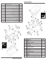
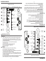
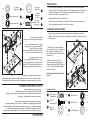
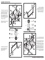
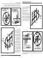
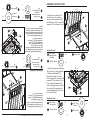
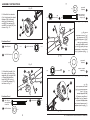
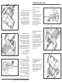
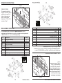
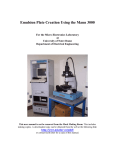
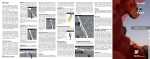
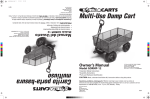
Questions, problems, missing parts? Before returning to
your retailer, visit us online at www.tricam.com or call our
customer service department at 1-800-867-6763,
9 a.m. - 4 p.m., CST, Monday-Friday.
REV - PD
CARRITO PORTABASURA DE
LUJO PARA JARDÍN
MODELO # GOR866D
MODEL # GOR866D
HEAVY DUTY GARDEN
DUMP CART
¿Preguntas, problemas, piezas faltantes? Antes de
volver a la tienda, visítenos en www.tricam.com o llame a
nuestro Departamento de Servicio al Cliente al
1-800-867-6763, de lunes a viernes de 9 a.m. a 4 p.m.,
hora central del Este.
REV - PD
Part
A
B
C
D
E
F
G
H
I
J
K
1
Description
Tray
Dump Lock Assembly
Rear Strut
Rear Frame
Rear Axle Assembly
Front Frame
Front Strut
Front Axle Assembly
Wheel
Handle
Hardware Kit (see Hardware Contents for details)
Quantity
1
1
2
1
1
1
2
1
4
1
1
CONTENIDO DEL PAQUETE
A
K
B
C
D
I
E
I
I
C
J
F
H
G
I
I
G
H
F
J
C
I
I
E
Pieza
A
B
C
D
E
F
G
H
I
J
K
I
D
C
B
K
A
Descripción
Bandeja
Ensamble del seguro del porta-basuray
Puntal posterior
Estructura posterior
Ensamble del eje posterior
Estructura delantera
Puntal delantero
Ensamble del eje frontal
Rueda
Manija
la sección Aditamentos
Kit de aditamentos (consulte
para obtener más detalles)
PACKAGE CONTENTS
Cantidad
1
1
2
1
1
1
2
1
4
1
1
1
ADITAMENTOS
Las imágenes no están a escala
Pieza
Descripción Cantidad
M8 x 20mm
Perno cabeza 2
de botón interna
DD
M8 x 20mm 12
Perno cabeza
de hongo
CC
M8 x 25mm
Perno cabeza 5
de hongo
BB
M8 x 60mm 1
Perno cabeza
de botón interna
AA
EE
20
Arandela
plana M8
FF
2
M6 x 20
Perno de
hombro
Imagen
HH
II
JJ
KK
LL
Pieza Descripción
4
Arandela
plana M12
4
Espaciador
para las
ruedas
Contratuerca
M8
Contratuerca
M12
Cantidad Imagen
20
4
2
Arandela
plana M6
MM
2
Contratuerca
M6
M8 x 20mm
Internal Button 2
Head Bolt
2
M6 x 20
Shoulder Bolt
1
DD
Llave allen
12
NN
M8 x 20mm
Carriage Bolt
9
CC
Arandela
plana M11
5
GG
M8 x 25mm
Carriage Bolt
Wheel Spacer
4
II
M12 Flat
Washer
4
JJ
M8 Lock Nut
20
KK
M12 Lock Nut
4
LL
M6 Lock Nut
2
MM
M6 Flat Washer 2
ADVERTENCIAS Y PRECAUCIONES
9
20
BB
EE
2
WARNING:
• Read, understand and follow ALL instructions before using this product.
• Do not exceed the overall maximum load capacity of 1,200 lbs. or the
maximum dumping load capacity of 500 lbs.The weight rating is based on
an evenly distributed load.
• Do not allow children to use the cart without supervision.
This cart is not a toy.
• Do not use this cart for transporting passengers.
• This cart is not intended for highway use.
• Do not exceed 5 mph.
CAUTION:
• Distribute the load evenly over the surface of the tray.
• Do not load items on the top edges of the tray.
• If any parts become damaged, broken or misplaced, do not use the cart
until replacement parts have been obtained.
• Do not use the cart on surfaces or for transporting objects that can cause
damage to the pneumatic tires or tubes. Do not inflate the tires to more
than 30 PSI (2.07 BAR).
• It is recommended that the cart be inspected for damage before each use.
• KEEP THESE INSTRUCTIONS FOR FURTHER REFERENCE.
WARNINGS AND CAUTIONS
M11 Flat
Washer
M8 Flat
Washer
M8 x 60mm
1
Internal Button
Head Bolt
Description Quantity
ADVERTENCIA:
• Lea, comprenda y siga TODAS las instrucciones
antes de utilizar este producto.
• No exceda la capacidad de carga total máxima de 544,31 kg o la
capacidad de carga de volcado máxima de 226,80 kg.
• El índice de peso está calculado en base a una carga distribuida
uniformemente.
• No permita que los niños utilicen el carrito sin supervisión.
Este carrito no es un juguete.
• No utilice este carrito para transportar pasajeros.
• Este carrito no está diseñado para utilizarse en autopistas.
• No exceda los 8 km/h.
PRECAUCIÓN:
• Distribuya la carga uniformemente sobre la superficie de la bandeja.
• No cargue artículos sobre los bordes superiores de la bandeja.
• Si alguna pieza se daña, rompe o pierde, no utilice el carrito hasta obtener
las piezas de repuesto.
• No utilice el carrito en superficies o para transportar objetos que dañen las
ruedas neumáticas o los tubos. No infle los neumáticos a más de 30 PSI
(2.07 BAR).
• Se recomienda que se revise el carrito para verificar que no tenga daños
antes de cada uso.
• GUARDE ESTAS INSTRUCCIONES PARA REFERENCIA FUTURA
GG
FF
AA
Part
NN
Allen Wrench
HH
Picture
1
Part Description Quantity
Picture
Images are not to scale
HARDWARE CONTENTS
2
CC
M8 x 20mm
Carriage Bolt
x4
EE
M6 x 20
Shoulder Bolt
x2
FF
M8 Flat
Washer
x4
3
JJ
M8 Lock Nut
x4
LL
M6 Lock Nut
x2
MM
M6 Flat Washer
x2
Hardware Used
PREPARACIÓN
Antes de comenzar a ensamblar el producto, asegúrese de tener todas las
piezas. Compare las piezas con la lista del contenido del paquete y el
diagrama anterior. No intente ensamblar el producto si falta alguna pieza o
si éstas están dañadas. Póngase en contacto con el Departamento de
Servicio al Cliente para obtener piezas de repuesto.
Tiempo estimado de ensamblaje: 30 minutos
Herramientas necesarias para el ensamblaje: Destornillador Phillips,
alicates y juego de dados (o dos llaves ajustables).
(No se incluyen las herramientas)
INSTRUCCIONES DE ENSAMBLAJE
MM
FF
JJ
H
LL
Hand tighten all bolts until after
Step 2.
EE
Attach the outer ends of the
steering linkage using two M6 x
20mm shoulder bolts (EE), M6 lock
nuts (LL), and M6 washers (MM),
as shown in Fig. 1.
1. Attach the front axle assembly
(H) to the front frame (F) using four
M8 x 20mm carriage bolts (CC),
four M8 lock nuts (JJ), and four M8
washers (FF).
F
CC
Nota: Durante cada paso del ensamblaje, ensamble todos los aditamentos y
apriete a mano. Una vez que todos los aditamentos estén instalados según
el paso correspondiente, apriételos.
Fig. 1
CC
1. Fije la estructura del eje frontal (H)
a la estructura delantera (F) con cuatro
pernos cabeza de hongo M8 x 20 mm
(CC), cuatro contratuercas M8 (JJ) y
cuatro arandelas M8 (FF).
F
Fije los extremos exteriores de la
varilla de dirección con dos pernos de
hombro M6 x 20 mm (EE),
contratuercas M6 (LL) y arandelas
(MM), como se muestra en la Fig. 1.
Apriete todos los pernos con la mano
hasta terminar el paso 2.
Note: During each step of assembly, assemble all hardware and hand
tighten. Once all the hardware is installed for that particular step, tighten all
the hardware.
Fig. 1
EE
LL
JJ
MM
ASSEMBLY INSTRUCTIONS
Estimated Assembly Time: 30 minutes
Tools Required for Assembly: Phillips screwdriver and metric socket set
(or two adjustable wrenches). (tools not included)
H
FF
Aditamentos utilizados
x4
Arandela
plana M8
FF
x2
M6 x 20
Perno de
hombro
EE
x4
M8 x 20mm
Perno cabeza
de hongo
CC
Before beginning assembly of product, make sure all parts are present.
Compare parts with package contents list and diagram above. If any part is
missing or damaged, do not attempt to assemble the product. Contact
customer service for replacement parts.
PREPARATION
JJ
x4
Contratuerca M8
LL
x2
Contratuerca M6
MM
Arandela
plana M6
x2
3
INSTRUCCIONES DE ENSAMBLAJE
Fig. 2
F
CC
G
FF
JJ
G
JJ
M8 Lock Nut
x4
CC
x4
H
M8 Flat
Washer
FF
FF
Apriete firmemente todos los
pernos de los pasos 1 y 2.
x4
2. Fije los puntales
delanteros (G) para conectar
el ensamble del eje frontal (H)
a la estructura delantera (F)
con cuatro pernos cabeza de
hongo M8 x 20 mm (CC),
cuatro contratuercas M8 (JJ)
y cuatro arandelas M8 (FF),
como se muestra en la Fig. 2.
C
M8 x 20mm
Carriage Bolt
JJ
CC
Aditamentos utilizados
x4
Contratuerca
M8
x4
Arandela
plana M8
FF
x4
M8 x 20mm
Perno cabeza
de hongo
CC
FF
H
CC
II
4
C
3. Slide the rear struts (C)
onto the ends of the rear
axle assembly (E), as
shown in Fig. 2.
E
Fig. 3
CC
Hardware Used
CC
JJ
Tighten all bolts from Step 1
and Step 2 securely.
2. Attach the front struts (G)
to connect the the front axle
assembly (H) to the front
frame (F) using four M8 x
20mm carriage bolts (CC),
using four M8 lock nuts (JJ),
and four M8 washers (FF),
as shown in Fig. 2.
Fig. 3
G
JJ
E
C
3. Deslice los puntales
posteriores (C) hacia los
extremos del ensamble del
eje posterior (E) como se
muestra en la Fig. 3.
FF
G
CC
C
F
Fig. 2
ASSEMBLY INSTRUCTIONS
4
5
NOTE: If the rear frame (D) is installed incorrectly, as shown in Fig. 6, the dump
lock assembly (B) installation in Step 6 will not engage when the cart tray (A) is
in the down position.
INCORRECT
CORRECT
SIDE HOLE IN FRONT
OF CENTER IS
SIDE HOLE IN REAR
OF CENTER IS
Center
Line
D
FRONT
OF TRAY
Center
Line
A
Fig. 5
FRONT
OF TRAY
Fig. 6
INSTRUCCIONES DE ENSAMBLAJE
4. El ensamble del eje
posterior (E) se fija a la
sección posterior de la
estructura posterior (D).
Revise dos veces la
ubicación de la estructura
posterior (D) antes de
ensamblarla en el tubo.
Los orificios laterales de
la estructura posterior (D)
deben estar mirando
hacia la parte posterior
de la bandeja (A).
Consulte las etiquetas
delantera y posterior en
la parte posterior de la
estructura posterior (D)
para confirmar que la
ubicación está correcta,
como se muestra en las
figuras 4, 5 y 6.
Fig. 4
D
EL FRENTE
DE LA BANDEJA
A
E
Fig. 5
E
4. The rear axle assembly (E)
attaches to the rear section of
the rear frame (D).
Double check the rear frame
(D) placement before
assembling to the tub. The
side holes on the rear frame
(D) must be towards the rear of
the tray (A). Please reference
the front and rear labels on the
backside of the rear frame (D)
to confirm correct placement,
as shown in Fig. 4, 5 and 6.
A
FRONT
OF TRAY
D
Fig. 4
ASSEMBLY INSTRUCTIONS
EL FRENTE
DE LA
BANDEJA
D
Fig. 6
EL FRENTE
DE LA
BANDEJA
A
Centro
Center
Line
Centro
Center
Line
EL ORIFICIO LATERAL
DETRÁS DEL CENTRO ESTÁ
EL ORIFICIO LATERAL
FRENTE AL CENTRO ESTÁ
CORRECTO
INCORRECTO
NOTA: Si la estructura posterior (D) no está instalada correctamente, como
se muestra en la Fig. 6, la instalación del ensamble del seguro del
porta-basura (B) en el paso 6 no se enganchará cuando la bandeja del carrito
(A) esté hacia abajo.
5
INSTRUCCIONES DE ENSAMBLAJE
6
Fig. 7
JJ
M8 Lock Nut
x6
BB
GG
CC
x6
5. Fije el ensamble del eje
posterior (E) con los puntales
posteriores (C) y la estructura
posterior (D) a la bandeja (A)
con pernos cabeza de hongo
M8 x 25 mm (BB), un pernos
cabeza de hongo M8 x 20 mm
(CC), seis contratuercas M8
(JJ), seis arandelas M11
(GG), y seis arandelas M8
(FF), como se muestra en la
Fig. 7.
M8 Flat
Washer
Use el pernos cabeza de
hongo M8 x 20 mm (CC) en la
parte central delantera de la
estructura posterior (D), como
se muestra en la Fig. 7.
FF
A
El orificio más
cercano a la parte
posterior de la
bandeja
El frente
de la
bandeja
D
Consulte las
paso 4, fig. 5
para confirmar
que la colocación
esta correcto
FF
JJ
E
Aditamentos utilizados
BB
x1
x6
CC
M8 x 20mm
Carriage Bolt
M11 Flat
Washer
x1
M8 x 20mm
pernos cabeza
de hongo
x5
M8 x 25mm
pernos cabeza
de hongo
Arandela plana M8
CC
GG
FF
x5
Front
of tray
x6
GG
x6
Arandela
plana M11
CC
Contratuerca M8
M8 x 25mm
Carriage Bolt
JJ
FF
Hole
Closer
to rear
of tray
A
GG
JJ
BB
JJ
BB
Hardware Used
E
Note correct
position of rear
frame as noted
in Step 4,
Figure 5.
D
x6
Contratuerca
M8
Use the one M8 x 20mm
carriage bolt bolt (CC) in the
front center location of the
rear frame (D), as shown in
Fig. 7.
5. Attach the rear axle
assembly (E) with the rear
struts (C) and the rear frame
(D) to the tray (A) using five
M8x25 carriage bolts (BB),
one M8 x 20mm carriage bolt
bolt (CC), six M8 lock nuts
(JJ), six M11 washers (GG),
and six M8 washers (FF), as
shown in Fig. 7.
Fig. 7
x6
ASSEMBLY INSTRUCTIONS
6
CC M8 x 20mm
Carriage Bolt
x3
FF
x3
M8 Flat Washer
7
JJ M8 Lock Nut
GG
M11 Flat
Washer
x3
x3
Hardware Used
7. Attach the dump lock assembly
(B) to the tray (A) using three M8
x 20mm carriage bolts (CC),
three M8 lock nuts (JJ), three
M11 washers (GG), and three M8
washers (FF), as shown in Fig. 9.
If the dump lock assembly (B)
does not engage when you lower
the cart tray (A), please double
check the placement of the rear
frame (D) in Step 4.
FF
M8 Flat Washer
DD M8 x 20mm
Internal Button
Head Bolt
JJ
FF
B
GG
A
CC
Fig. 9
x2
x2
JJ M8 Lock Nut
x2
Hardware Used
F
DD
FF
JJ
DD
6. Attach the rear frame (D) to
the front frame (F) using two
internal button head bolts (DD),
two M8 lock nuts (II), and two M8
washers (FF), as shown in Fig. 8.
D
INSTRUCCIONES DE ENSAMBLAJE
Fig. 8
6. Fije la estructura posterior
(D) a la estructura delantera (F)
pernos cabeza de botón interna
M8 x 20 mm (DD), dos
contratuercas M8 (II) y cuatro
arandelas M8 (FF), como se
muestra en la Fig. 8.
D
DD
JJ
DD
F
Aditamentos utilizados
Arandela plana
M8
FF
M8 x 20mm
Perno cabeza
de botón interna
DD
JJ Contratuerca
M8
x2
x2
x2
Fig. 9
7. Fije el ensamble del seguro del
porta-basura (B) a la bandeja (A)
con tres pernos cabeza de hongo
M8 x 20 mm (CC), tres
contratuercas M8 (JJ), tres
arandelas M11 (GG), y tres
arandelas M8 (FF), como se
muestra en la Fig. 9.
Si el ensamble del seguro del
porta-basura (B) no se engancha
cuando baja la bandeja del carrito
(A), revise dos veces la ubicación
de la estructura posterior (D) en el
paso 4.
CC
A
GG
B
FF
JJ
Aditamentos utilizados
CC M8 x 20mm
pernos cabeza
de hongo
FF
Fig. 8
Arandela plana
M8
x3
GG
x3
Arandela
plana M11
x3
JJ Contratuerca
M8
7
ASSEMBLY INSTRUCTIONS
x3
INSTRUCCIONES DE ENSAMBLAJE
8
Fig. 10
M8 Lock Nut
x1
I
JJ
8. Fije las cuatro ruedas
(I) colocando primero los
espaciadores para las
ruedas (HH) en cada eje,
y luego las ruedas (I) y
las arandelas planas
M12 (II), y las
contratuercas M12 (KK),
como se muestra en la
Fig. 10.
x1
HH
II
KK
Aditamentos utilizados
HH
II
X4
Arandela
plana M12
X4
Espaciador
para las ruedas
KK
FF
X4
Contratuerca
M12
Fig. 11
FF
X4
JJ
X4
M12 Lock Nut
9. Fije la manija (J) a la
horquilla en el ensamble
del eje frontal (H) con el
perno cabeza de botón
interna M8 x 60 mm
(AA), la contratuerca M8
(JJ) y la arandela M8
(FF), como se muestra
en la Fig. 11.
M8 Flat Washer
M12 Flat Washer
KK
H
J
AA
Aditamentos utilizados
AA
FF
X1
X4
HH
M8 x 60mm
Perno cabeza
de botón interna
Arandela
plana M8
M8 x 60mm
Internal Button
Head Bolt
H
JJ
Wheel Spacer
II
X1
JJ Contratuerca
M8
I
FF
AA
Hardware Used
AA
J
9. Attach the handle (J) to
the yoke on the front axle
assembly (H) using the M8
x 60mm internal button
head (AA), M8 lock nut
(JJ), and M8 washer (FF),
as shown in Fig. 11.
Fig. 11
II
HH
Hardware Used
KK
8. Attach the four wheels
(I) by first placing the wheel
spacers (HH) onto each
axle, then the wheels (I)
and M12 flat washers (II),
and M12 lock nuts (KK), as
shown in Fig. 10.
x1
x1
Fig. 10
ASSEMBLY INSTRUCTIONS
8
9
2. RETURNING THE TRAY
TO THE LOWERED
POSITION
Return the tray back to the
lowered position and verify
that the dumping release
handle locks in place, as
shown in Fig. 3.
Fig. 3
1. USING THE DUMPING
FEATURE
To use the dumping feature,
pull the dumping release
handle forward in order to
release the tray from the
locking mechanism. Lift the
release handle in order to
rotate the tray upward into
the dumping position, as
shown in Fig. 2.
Fig. 2
USING THE SWIVEL
HANDLE
1. Remove clips and
cotter pins.
2. Rotate the handle and
insert cotter pin. Secure
by attaching the clip.
3. The second cotter pin
is used to attach the
handle to the trailer hitch,
as shown in Fig. 1.
INSTRUCCIONES DE OPERACIÓN
PARA UTILIZAR LA MANIJA
GIRATORIA
1. Retire los sujetadores y
los pasadores de chaveta.
2. Gire la manija e inserte
los pasadores de chaveta.
Fíjela con el sujetador.
3. El segundo pasador de
chaveta se usa para fijar la
manija al enganche de
remolque, como se muestra
en la Fig. 1.
Fig. 1
Fig. 2
1. PARA UTILIZAR LA
CARACTERÍSTICA DE
VOLCADO
Para utilizar la característica
de volcado, jale la manija de
liberación de volcado hacia
delante para liberar la
bandeja del mecanismo de
bloqueo. Levante la manija
de liberación para girar la
bandeja hacia arriba a la
posición de volcado, como
se muestra en la Fig. 2.
Fig. 3
2. PARA VOLVER A
COLOCAR LA BANDEJA
EN LA POSICIÓN BAJA
Vuelva a colocar la bandeja
en la posición baja y
verifique que la manija de
liberación de volcado se
bloquee en su lugar, como
se muestra en la Fig. 3.
Fig. 1
OPERATION INSTRUCTIONS
9
INSTRUCCIONES DE OPERACIÓN
Printed in China
Fig. 1
BOLSILLOS LATERALES
Para incrementar los pies
cúbicos de este artículo, estos
8 bolsillos pueden utilizarse en
los paneles laterales como se
muestra. Estos bolsillos eal
dimensionada de 1.9cm x
5.08cm, como se muestra en
la Fig. 1.
10
I
H
G
I
F
E
K
LISTA DE PIEZAS DE REPUESTO
Para obtener piezas de repuesto, visítenos en www.tricam.com o llame a
nuestro Departamento de Servicio al Cliente al 1-800-867-6763, de lunes a
viernes de 9 a.m. a 4 p.m., hora central estándar.
Pieza
B
C
D
E
F
G
H
I
J
K
Descripción
Cantidad
Ensamble del seguro del porta-basuray
1
Puntal posterior
2
Estructura posterior
1
Ensamble del eje posterior
1
Estructura delantera
1
Puntal delantero
2
Ensamble del eje frontal
1
Rueda
4
Manija
1
Kit de aditamentos (consulte la sección Aditamentos para obtener más detalles) 1
B
J
C
I
I
D
B
Quantity
1
2
1
1
1
2
1
4
1
1
Description
Dump Lock Assembly
Rear Strut
Rear Frame
Rear Axle Assembly
Front Frame
Front Strut
Front Axle Assembly
Wheel
Handle
Hardware Kit (see Hardware Contents for details)
K
D
I
E
I
C
J
Part
B
C
D
E
F
G
H
I
J
K
For replacement parts, visit us online at www.tricam.com to fill out a
replacement parts submission form or call our customer service department at
1-800-867-6763, 9 a.m. - 4 p.m., CST, Monday-Friday
REPLACEMENT PARTS LIST
STAKE OUT SIDES
To increase the cubic foot
capacity of this item, these 8
pockets can be used to fit
stake out side panels as
shown. Actual pocket
dimensions: 0.75in x 2.0in
as shown in Fig. 1.
F
I
G
H
Fig. 1
I
Impreso en China
10
OPERATION INSTRUCTIONS