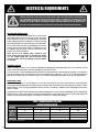
1
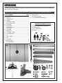
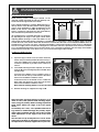
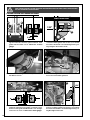
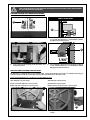
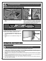
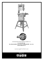
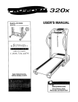
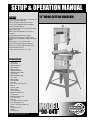
SETUP & OPERATION MANUAL FEATURES Sturdy welded steel frame & precision balanced wheels with replaceable tires. 12” WOOD CUTTING BANDSAW Easy-to-assemble open-base steel stand. Precision easy-adjust European style blade guide bearings included. Two cutting speeds for excellent results in either hard or soft woods. Miter gauge with aluminum crosscut fence included. Deluxe dual-position rip fence system. Hinged doors and easily accessible blade tension knob, for fast blade changes and adjustments. Extra-large 21 ½ x 15 ¾ cast-iron table. Smooth running heavy-duty 2/3 HP motor. Safety lock-out switch with removable key to prevent unauthorized use. Multi-size dust port fits 4”, 3”, or 2” hose. SPECIFICATIONS • Wheel size 12” (305 mm) • Wheel speeds (2) 445 & 970 rpm • Blade speeds (2) 1444 & 3150 lin. fpm • Maximum blade width 3/4” (20 mm) • Minimum blade width 1⁄8” (3 mm) • Blade length 88” (2240 mm) • Table size 21 ½” x 15 ¾” (548 x 400 mm) • Table tilt 0° to 45° (right) • Table height 37 3/8” (950 mm) • Maximum width of cut 12” (305 mm) • Maximum depth of cut 6 1/2” (165 mm) • Dust port 4”, 3” and 2” (102, 76 or 51mm) • Base dimensions (l x w) 18 1/4” x 15 3/4” (465 x 400 mm) • Motor 2/3 HP, 120 V, 6,4 A • Weight 165 lbs (75 kg) Version #1_Revision #2 - December 2014 © Copyright General International MODEL # 90-040 GENERAL® INTERNATIONAL 8360 Champ-d’Eau, Montreal (Quebec) Canada H1P 1Y3 Telephone (514) 326-1161 • Fax (514) 326-5555 • www.general.ca THANK YOU for choosing this General® International model 90-040 12” Wood Cutting Bandsaw. This bandsaw has been carefully tested and inspected before shipment and if properly used and maintained, will provide you with years of reliable service. For your safety, as well as to ensure optimum performance and trouble-free operation, and to get the most from your investment, please take the time to read this manual before assembling, installing and operating the unit. The manual’s purpose is to familiarize you with the safe operation, basic function, and features of this bandsaw as well as the set-up, maintenance and identification of its parts and components. This manual is not intended as a substitute for formal woodworking instruction, nor to offer the user instruction in the craft of woodworking. If you are not sure about the safety of performing a certain operation or procedure, do not proceed until you can confirm, from knowledgeable and qualified sources, that it is safe to do so. Once you’ve read through these instructions, keep this manual handy for future reference. DISCLAIMER: The information and specifications in this manual pertain to the unit as it was supplied from the factory at the time of printing. Because we are committed to making constant improvements, General® International reserves the right to make changes to components, parts or features of this unit as deemed necessary, without prior notice and without obligation to install any such changes on previously delivered units. Reasonable care is taken at the factory to ensure that the specifications and information in this manual corresponds with that of the unit with which it was supplied. However, special orders and “after factory” modifications may render some or all information in this manual inapplicable to your machine. Further, as several generations of this model of wood cutting Bandsaw and several versions of this manual may be in circulation, if you own an earlier or later version of this unit, this manual may not depict your unit exactly. If you have any doubts or questions contact your retailer or our support line with the model and serial number of your unit for clarification. GENERAL® INTERNATIONAL WARRANTY All component parts of General® International and Excalibur by General International® products are carefully inspected during all stages of production and each unit is thoroughly inspected upon completion of assembly. Limited Lifetime Warranty Because of our commitment to quality and customer satisfaction, General® International agrees to repair or replace any part or component which upon examination, proves to be defective in either workmanship or material to the original purchaser for the life of the tool. However, the Limited Lifetime Warranty does not cover any product used for professional or commercial production purposes nor for industrial or educational applications. Such cases are covered by our Standard 2-year Limited Warranty only. The Limited Lifetime Warranty is also subject to the “Conditions and Exceptions” as listed below. Standard 2-Year Limited Warranty All products not covered by our lifetime warranty including products used in commercial, industrial and educational applications are warranted for a period of 2 years (24 months) from the date of purchase. General® International agrees to repair or replace any part or component which upon examination, proves to be defective in either workmanship or material to the original purchaser during this 2-year warranty period, subject to the “conditions and exceptions” as listed below. To file a Claim To file a claim under our Standard 2-year Limited Warranty or under our Limited Lifetime Warranty, all defective parts, components or machinery must be returned freight or postage prepaid to General® International, or to a nearby distributor, repair center or other location designated by General® International. For further details call our service department at 1-888-949-1161 or your local distributor for assistance when filing your claim. Along with the return of the product being claimed for warranty, a copy of the original proof of purchase and a “letter of claim” must be included (a warranty claim form can also be used and can be obtained, upon request, from General® International or an authorized distributor) clearly stating the model and serial number of the unit (if applicable) and including an explanation of the complaint or presumed defect in material or workmanship. CONDITIONS AND EXCEPTIONS: This coverage is extended to the original purchaser only. Prior warranty registration is not required but documented proof of purchase i.e. a copy of original sales invoice or receipt showing the date and location of the purchase as well as the purchase price paid, must be provided at the time of claim. Warranty does not include failures, breakage or defects deemed after inspection by General® International to have been directly or indirectly caused by or resulting from; improper use, or lack of or improper maintenance, misuse or abuse, negligence, accidents, damage in handling or transport, or normal wear and tear of any generally considered consumable parts or components. Repairs made without the written consent of General® International will void all warranty. TABLE OF CONTENTS Rules for safe operation...................................................................................................... 5 Electrical requirements....................................................................................................... 6 Identification of main parts and components................................................................... 7 Unpacking........................................................................................................................... 8 Basic functions.................................................................................................................... 9 Cleaning............................................................................................................................. 9 Placement within the shop................................................................................................. 9 Assembly instructions.................................................................................................. 10-13 Assembling the stand........................................................................................................................................ 10 Attaching the bandsaw to the stand.............................................................................................................. 11 Installing the work table and the 90° stop................................................................................................. 11-12 Installing the rip fence system..................................................................................................................... 12-13 Installing the push stick holder......................................................................................................................... 13 Basic adjustments and controls.................................................................................. 14-20 Connecting to a power source........................................................................................................................ 14 On/Off power switch.......................................................................................................................................... 14 Choosing and changing blades................................................................................................................ 14-16 Adjusting blade tension.................................................................................................................................... 16 Blade tracking adjustment............................................................................................................................... 17 Adjusting the upper and lower blade guides................................................................................................ 18 Adjusting the upper and lower thrust guides................................................................................................. 19 Selecting and changing the blade speed............................................................................................... 19-20 Adjusting the upper blade guard................................................................................................................... 20 Operating Instructions................................................................................................. 20-22 Checklist before starting................................................................................................................................... 20 Connecting to a dust collector........................................................................................................................ 21 Cutting curves.................................................................................................................................................... 21 Cutting circles..................................................................................................................................................... 21 Using the miter gauge........................................................................................................................................... Maintenance................................................................................................................ 22-23 Cleaning............................................................................................................................................................. 22 Changing the belt and aligning the pulleys.................................................................................................. 22 Wheel tires........................................................................................................................................................... 23 Motor................................................................................................................................................................... 23 Lubrication.......................................................................................................................................................... 23 Parts list & diagram..................................................................................................... 24-29 Contact information......................................................................................................... 30 RULES FOR SAFE OPERATION To help ensure safe operation, please take a moment to learn the machine’s applications and limitations, as well as potential hazards. General® International disclaims any real or implied warranty and hold itself harmless for any injury that may result from the improper use of it’s equipment. 1. Do not operate the bandsaw when tired, distracted or under the effects of drugs, alcohol or any medI cation that impairs reflexes or alertness. 2. The work area should be well lit, clean and free of debris. 3. Keep children and visitors at a safe distance when the bandsaw is in operation; do not permit them to operate the bandsaw. 4. Childproof and tamper proof your shop and all machinery with locks, master electrical switches and switch keys, to prevent unauthorized or unsupervised use. 5. STAY ALERT! Give your work your undivided attention. Even a momentary distraction can lead to serious injury. 6. Fine particulate dust is a carcinogen that can be hazardous to health. Work in a well-ventilated area. Wear face, eye, ear, respiratory and body protection devices. 7. Do not wear loose clothing, gloves, bracelets, necklaces or other jewelry while the bandsaw is in operation. 8. Be sure that adjusting wrenches, tools, drinks and other clutter are removed from the machine and/or the table surface before operating. 9. Keep hands well away from the blade and all moving parts. Use a brush, not hands, to clear away chips and dust. 10.Adjust and position the blade close as possible to the workpiece. guard as 11.Adjust blade tension and tracking before starting to cut. 12.Blade teeth must point down toward the table. 13.Be sure that the blade has gained full operating speed before starting to cut. 14.Always use a clean, properly sharpened blade. Dirty or dull blades are unsafe and can lead to accidents. 15.Use suitable workpiece support if the workpiece does not have a flat surface. 16.Do not work on long stock without adequate support on the out feed end of the table. 17.Do not push or force stock into the blade. The band saw will perform better and more safely when work ing at the rate for which it was designed. 18.Avoid working from awkward or off balance posi tions. Do not overreach and keep both feet on floor. 19.Keep guards in place and in working order. If a guard must be removed for maintenance or clean ing be sure it is properly re-attached before using the saw again. 20.Never leave the machine unattended while it is run- ning or with the power on. 21.Use of parts and accessories NOT recommended by General® International may result in equipment malfunction or risk of injury. 22.Never stand on machinery. Serious injury could re sult if the tool is tipped over or if the blade is unintentionally contacted. 23.Always disconnect the saw from the power source before servicing or changing accessories such as blades, or before performing any mainte nance or cleaning, or if the machine will be left unattended. 24.Make sure that the switch is in the “OFF” position before plugging in the power cord. 25.Make sure the machine is properly grounded. If equipped with a 3-prong plug it should be used with a three-pole receptacle. Never remove the third prong. 26.Do not use this bandsaw for other than its intended use. If used for other purposes, General® International disclaims any real or implied warranty andholds itself harmless for any in jury, which may resultfrom that use. 5 ELECTRICAL REQUIREMENTS BEFORE CONNECTING THE MACHINE TO THE POWER SOURCE, VERIFY THAT THE VOLTAGE OF YOUR POWER SUPPLY CORRESPONDS WITH THE VOLTAGE SPECIFIED ON THE MOTOR I.D. NAMEPLATE. A POWER SOURCE WITH GREATER VOLTAGE THAN NEEDED CAN RESULT IN SERIOUS INJURY TO THE USER AS WELL AS DAMAGE TO THE MACHINE. IF IN DOUBT, CONTACT A QUALIFIED ELECTRICIAN BEFORE CONNECTING TO THE POWER SOURCE. THIS TOOL IS FOR INDOOR USE ONLY. DO NOT EXPOSE TO RAIN OR USE IN WET OR DAMP LOCATIONS. GROUNDING INSTRUCTIONS In the event of an electrical malfunction or short circuit, grounding reduces the risk of electric shock. The motor of this machine is wired for 120 V single phase operation and is equipped with a 3-conductor cord and a 3-prong grounding plug A to fit a grounded type receptacle B. Do not remove the 3rd prong (grounding pin) to make it fit into an old 2-hole wall socket or extension cord. If an adaptor plug is used C, it must be attached to the metal screw of the receptacle. A Note: The use of an adaptor plug is illegal in some areas. Check your local codes. If you have any doubts or if the supplied plug does not correspond to your electrical outlet, consult a qualified electrician before proceeding. B C CIRCUIT CAPACITY Make sure that the wires in your circuit are capable of handling the amperage draw from your machine, as well as any other machines that could be operating on the same circuit. If you are unsure, consult a qualified electrician. If the circuit breaker trips or the fuse blows regularly, your machine may be operating on a circuit that is close to its amperage draw capacity. However, if an unusual amperage draw does not exist and a power failure still occurs, contact a qualified technician or our service department. EXTENSION CORDS If you find it necessary to use an extension cord with your machine, use only 3-wire extension cords that have 3-prong grounding plug and a matching 3-pole receptacle that accepts the tool’s plug. Repair or replace a damaged extension cord or plug immediately. Make sure the cord rating is suitable for the amperage listed on the motor I.D. plate. An undersized cord will cause a drop in line voltage resulting in loss of power and overheating. The accompanying chart shows the correct size extension cord to be used based on cord length and motor I.D. plate amp rating. If in doubt, use the next heavier gauge. The smaller the number, the heavier the gauge. TABLE - MINIMUM GAUGE FOR CORD EXTENSION CORD LENGTH AMPERES 50 feet 100 feet 200 feet 300 feet <5 18 16 16 14 6 to 10 18 16 14 12 10 to 12 16 16 14 12 12 to 16 14 12 *NR *NR *NR = Not Recommended 6 IDENTIFICATION OF MAIN PARTS AND COMPONENTS E F D G H C I B N L J K A M A. STAND H. BLADE B. RIP FENCE I. MITER GAUGE C. ON/OFF SWITCH WITH REMOVABLE KEY J. LOWER DOOR LOCK KNOB D. UPPER WHEEL DOOR K. BELT TENSION KNOB E. BLADE TENSION KNOB L. LOWER WHEEL DOOR F. UPPER DOOR LOCK KNOB M. DUST TRAY G. BLADE GUARD LOCK KNOB N. TABLE TILT SCALE 7 UNPACKING Carefully unpack and remove the unit and its components from the box and check for missing or damaged items as per the list of contents below. NOTE: PLEASE REPORT ANY DAMAGED OR MISSING ITEMS TO YOUR GENERAL® INTERNATIONAL DISTRIBUTOR IMMEDIATELY. U. CARRIAGE BOLT........................................................................ 1 V. RIP FENCE GUIDE HOOK.......................................................... 1 W. 10 - 13 MM COMBINATION WRENCH..................................... 1 L IST OF CONTENTS QTY A. WORK TABLE............................................................................. 1 B. PUSH STICK................................................................................ 1 C. FRONT FENCE RAIL .................................................................. 1 D. RIP FENCE................................................................................. 1 E. CROSS BRACE (LONG)............................................................ 2 F. CROSS BRACE (SHORT)............................................................ 2 G. SUPPORT LEG............................................................................ 4 H. MITER GAUGE........................................................................... 1 I. RIP FENCE HANDLE................................................................... 1 J. TABLE INSERT............................................................................. 1 K. LOCK KNOB.............................................................................. 4 L. KNURLED NUT........................................................................... 1 M. FLAT WASHER (LARGE)............................................................. 4 N. FLAT WASHER (SMALL)............................................................ 33 O. NUT.......................................................................................... 28 P. TABLE STOP BOLT....................................................................... 1 Q. BOLT ......................................................................................... 5 R. CAP SCREW.............................................................................. 4 S. CARRIAGE BOLT...................................................................... 23 T. CAP SCREW W/NUT.................................................................. 1 A ADDITIONAL REQUIREMENTS FOR SET UP A. 2 EXTRA PEOPLE FOR HELP WITH LIFTING B. 14 MM WRENCH C.3 & 5 MM ALLEN KEYS D. SQUARE A B D C B C D E F G I J K L M N H 8 P Q R S T U V W O BASIC FUNCTIONS This 12” Wood Cutting Bandsaw is supplied with a 1/2” general purpose blade and is designed to accommodate blade widths from 1/8” to 3/4”. Ideal blade length for this model 90-040 is 88” (2240 mm). Note: Generally speaking, because the upper wheel height is somewhat adjustable (to allow for blade tensioning), a blade length variation of plus or minus 1/2” from the “ideal blade length” can be accommodated. Maximum inboard width of cut is 12”. For cutting thicker stock or for resawing, the maximum depth of cut (or max. workpiece height) is 6 1/2”. An adjustable rip fence is supplied to serve as a straightedge to guide the workpiece for longer rip cuts. The fence can easily be removed and set aside when not required, for example when making curved cuts. CLEANING The protective coating on the saw table prevents rust from forming during shipping and storage. Remove it by rubbing with a rag dipped in kerosene, mineral spirits or paint thinner. (Dispose of potentially flammable solvent-soaked rags according to manufacturer’s safety recommendations). A putty knife, held flat to avoid scratching the surface, may also be used to scrape off the coating followed by clean-up with solvent. Avoid rubbing the saw’s painted surfaces, as many solvent-based products will remove paint. To prevent rust, apply a light coating of paste wax or use regular applications of any after-market surface protectant or rust inhibitor. TIP: WITH A SCREW DRIVER, PUSH A SOLVENT-SATURATED RAG INTO THE T-SLOTS TO REMOVE THE GREASE. PLACEMENT WITHIN THE SHOP / SAFETY ZONE PLACEMENT WITHIN THE SHOP This machine should be installed and operated only on a solid, flat and stable floor that is able to support the weight of the machine (165 lbs - 75 kg) and the operator. Using the dimensions shown as a guideline, plan for placement within your shop that will allow the operator to work unencumbered and unobstructed by foot traffic (either passing shop visitors or other shop workers) or other tools or machinery. ESTABLISHING A SAFETY ZONE 65" For shops with frequent visitors or multiple operators, it is advisable to establish a safety zone around shop machinery. A clearly defined “no-go” zone on the floor around each machine can help avoid accidents that could cause injury to either the operator or the shop visitor. It is advisable to take a few moments to either paint (using non-slip paint) or using tape, define on the floor the limits or perimeter of each machines safety zone. Take steps to ensure that all operators and shop visitors are aware that these areas are off limits whenever a machine is running for everyone but the individual operating the unit. 27" 25" 9 ASSEMBLY INSTRUCTIONS BEFORE ASSEMBLING, MAKE SURE THAT THE SWITCH IS IN THE “OFF” POSITION AND THAT THE POWER CORD IS UNPLUGGED. DO NOT PLUG IN OR TURN ON THE MACHINE UNTIL YOU HAVE COMPLETED THE ASSEMBLY AND INSTALLATION STEPS DESCRIBED IN THIS SECTION OF THE MANUAL. ASSEMBLING THE STAND 1. Attach two stand legs and a small cross brace using the carriage bolts, flat washers and nuts. Note: Tighten the nuts by hand only. 10 2. Repeat with the two longer cross braces as shown. Note: Tighten the nuts by hand only. 3. Attach a third stand leg using the carriage bolts, flat washers and nuts. Note: Tighten the nuts by hand only. 4. Repeat with the last leg. 5. Secure the four cross braces tightening the bolts, flat washers and the nuts with a 13 mm wrench. 6. Place the assembled stand upright on a flat surface. BEFORE ASSEMBLING, MAKE SURE THAT THE SWITCH IS IN THE “OFF” POSITION AND THAT THE POWER CORD IS UNPLUGGED. DO NOT PLUG IN OR TURN ON THE MACHINE UNTIL YOU HAVE COMPLETED THE ASSEMBLY AND INSTALLATION STEPS DESCRIBED IN THIS SECTION OF THE MANUAL. ATTACHING THE MACHINE TO STAND THE BANDSAW IS HEAVY. DO NOT OVER-EXERT. THE HELP OF ASSISTANTS WILL BE NEEDED FOR THE FOLLOWING STEP. DO NOT GRIP THE BANDSAW BY THE LOWER WHEEL COVER DOOR WHEN LIFTING. KEEP HANDS AWAY FROM BLADE AT ALL TIMES. A 1. Place the machine on the stand with the help of two assistants. 2. Secure the machine to the stand using carriage bolts, flat washers, nuts, and a 13 mm wrench, and tighten all the stand mounting nuts A. INSTALLING THE TABLE AND THE 90° STOP 1. Install the table on its base by guiding the blade through the table slot as shown. 2. Using a 5 mm Allen key, secure the table to its base by tightening the four supplied cap screws and four flat washers, B A 3. Loosen the table by turning the lock lever A counterclockwise. 4. Tilt the table by turning the knob B. 11 BEFORE ASSEMBLING, MAKE SURE THAT THE SWITCH IS IN THE “OFF” POSITION AND THAT THE POWER CORD IS UNPLUGGED. DO NOT PLUG IN OR TURN ON THE MACHINE UNTIL YOU HAVE COMPLETED THE ASSEMBLY AND INSTALLATION STEPS DESCRIBED IN THIS SECTION OF THE MANUAL. INSTALLING THE TABLE AND THE 90° STOP (CONTINUED) D F C 5. Screw the table stop bolt with jam nut in the mounting hole C under the table, and then set the table in the horizontal position by hand. E 6. Place a combination square on the table against the blade D, and adjust the table until threre is no space between the square and the blade. Tighten the lock lever A. Loosen the table bolt until its head touches the machine E, and then tighten the jam nut F. INSTALLING THE RIP FENCE 12 1. Slide a flat washer onto each of the four lock knobs. 2. Loosely screw the four lock knobs in the mounting holes in the underside of the table as shown. 3. Fit the rail onto the lock knobs as shown. 4. Secure the rail in place by tightening the lock knobs. BEFORE ASSEMBLING, MAKE SURE THAT THE SWITCH IS IN THE “OFF” POSITION AND THAT THE POWER CORD IS UNPLUGGED. DO NOT PLUG IN OR TURN ON THE MACHINE UNTIL YOU HAVE COMPLETED THE ASSEMBLY AND INSTALLATION STEPS DESCRIBED IN THIS SECTION OF THE MANUAL. INSTALLING THE RIP FENCE (CONTINUED) 5. Thread the lock knob of the fence handle. 6. Slide the fence handle into the fence slot as shown. B C D A 7. Pull the handle back towards you and place the fence on the rail. Note: the screw A serves as a stop for the fence. 8. Insert the small carriage bolt into the guide hook, and then slide a flat washer onto it B. Screw on the knurled nut C, and slide the bolt head into the slot under the guide until the stop is against the table edge. Tighten the knurled nut to hold the guide in place D. INSTALLATING THE PUSH STICK HOLDER A 1. Thread the cap screw A in the mounting hole on the left side of the machine, and tighten the jam nut to secure it in place. 2. Hang the push stick to keep it handy. 13 BASIC ADJUSTMENTS & CONTROLS TO REDUCE THE RISK OF SHOCK OR FIRE DO NOT OPERATE THE UNIT WITH A DAMAGED POWER CORD OR PLUG. REPLACE DAMAGED CORD OR PLUG IMMEDIATELY. TO AVOID UNEXPECTED OR UNINTENTIONAL START-UP, MAKE SURE THE POWER SWITCH IS IN THE OFF POSITION BEFORE CONNECTING TO A POWER SOURCE. CONNECTING TO A POWER SOURCE Once the assembly steps have been completed, plug the power cord into an appropriate outlet. SWITCH OFF Refer back to the section entitled “Electrical Requirements” and make sure all requirements and grounding instructions are followed. When operations have been completed unplug the saw from the power source. TO AVOID UNEXPECTED OR UNINTENTIONAL START-UP, MAKE SURE THAT THE POWER SWITCH IS IN THE OFF POSITION BEFORE CONNECTING TO A POWER SOURCE. ON/OFF POWER SWITCH The bandsaw is equipped with a rocker type ON/OFF switch A that is equipped with a lock-out key. A To prevent unwanted or unauthorized start-up or usage remove the lock-out key D and store it in a safe place. To start the bandsaw, insert the lock-out key and pull up the switch B. To stop the bandsaw, push down on the power switch C. When the saw comes to a complete stop, remove the lock-out key D by gently pulling it outward. B D C POWER ON POWER OFF LOCK-OUT KEY (PREVENTS START-UP WHEN REMOVED) CHOOSING AND CHANGING THE BLADE There are a variety of different types of bandsaw blades on the market to suit various cutting applications. The accompanying “Blade Selection” chart provides a general reference tool; your results may vary based on usage, experience and personal preference. Ask your local tool dealer for suggestions for 88” bandsaw blades in 1/8” to 3/4” widths, based on what is available in your area. Some general guidelines to consider when choosing bandsaw blades: BLADE SELECTION OPERATION RECOMMDED BLADE CROSS CUTTING 1/4", 3/8", 1/2" MITERING 1/4", 3/8", 1/2" BEVELING 1/4", 3/8", 1/2" COMPOUND CUTTING 1/4", 3/8", 1/2" CIRCLE CUTTING See cutting circles Wider blades with coarse teeth are best suited to cutting straight CURVE CUTTING 1/8", 1/4" lines, re-sawing and for sweeping curves, but will not turn tight corners. They will cut quickly and aggressively but do have a tendency to bind (get stuck in the cut) if turned to sharply. Narrower, thinner blades with finer teeth will cut more slowly but can turn much tighter corners for cutting more intricate work. 14 CHOOSING AND CHANGING THE BLADE (CONTINUED) Common causes of blade breakage: • Poor blade guide alignment and adjustment. • Too much blade tension. • Forcing or twisting a wide blade around a short radius. • Setting the blade guard too high above the workpiece. • Feeding the workpiece too quickly. • Lumpy or improperly finished braze or weld on the blade. • Dull teeth. • Continuous running blade when not cutting. MAKE SURE THE MACHINE HAS BEEN TURNED OFF AND UNPLUGGED FROM THE POWER SOURCE BEFORE PERFORMING ANY MAINTENANCE OR ADJUSTMENTS. A 1. Loosen the blade guard lock knob as shown. 2. Lower the blade guard halfway by turning the knob A clockwise. 3. Loosen the four lock knobs, and remove the fence rail. 4. Remove the insert from the table using a screwdriver. B C 5. Open the upper door by turning the knob B clock- 6. Open the lower door by turning the knob C clockwise. wise. 15 MAKE SURE THE MACHINE HAS BEEN TURNED OFF AND UNPLUGGED FROM THE POWER SOURCE BEFORE PERFORMING ANY MAINTENANCE OR ADJUSTMENTS. CHOOSING AND CHANGING THE BLADE (CONTINUED) D 7. Tilt the table to the right as shown, and then pivot the lower guard to the left D. 8. Remove the dust tray as shown. RIGHT SIDE VIEW E 9. Release the blade tension by turning the tension E lever E to the right. Remove the blade carefully starting on the right as shown. 10.To install a blade, repeat the previous steps in reverse order, making sure that the blade is installed with the teeth pointing forward and down as shown. Note: With the blade installed proceed to the tensioning and tracking instructions. ADJUSTING THE BLADE TENSION A properly tensioned blade is critical to obtaining maximum performance from any bandsaw. A properly tensioned blade will last longer and be much less likely to break prematurely. If the blade tension is too loose you will notice that the blade will have a tendency to drift or slip off-line when cutting and you will have more difficulty controlling your cuts. A blade that is tensioned too tightly will break prematurely. This bandsaw is equipped with a blade tension scale, which can be used as a reference for the ideal setting with various blade widths. A B 1. Turn the blade tension knob A clockwise, raising the upper wheel to tighten the blade. Turn the knob counter-clockwise to lower the upper wheel, loosening the blade. Note: Changes in blade width and the type of material being cut will have an effect on the blade tension. 16 Note: The tension indicator B at the rear of the upper wheel housing indicates the proper tension for the various blade widths. Set the tension indicator to correspond with the width of the blade in use. MAKE SURE THE MACHINE HAS BEEN TURNED OFF AND UNPLUGGED FROM THE POWER SOURCE BEFORE PERFORMING ANY MAINTENANCE OR ADJUSTMENTS. ADJUSTING BLADE TRACKING Blade tracking means centering the blade on the wheels A. Ideally, the blade should stay relatively centered on both the upper and lower wheels. B 3mm (1/8") Due to natural variations in castings, blade thickness or density and tire wear, absolute perfect centering alignment is rarely attainable. A slight misalignment of the blade on the wheels is inevitable and as long as it is kept to a minimum (following the steps listed below) will not hinder the performance of the saw. A This misalignment is controlled and kept to a minimum by adjusting the tilt angle of the upper wheel. When adjusting blade tracking to center the blade on the wheels and assuming that perfect centering is not attainable, it is preferable to have the blade slightly off-center towards the front of the wheels rather than towards the rear because the teeth on most bandsaw blades have alternating hook (one inner, one outer) – therefore if the blade is centered too far back on the wheel (or if the blade tension is too tight), inner hooked teeth will dig into the wheel tire and cause premature wear of the tire. Nonetheless, to avoid having the blade come off of the wheels on it’s own during operation, the front edge of the blades teeth should never be any closer than 3 mm (1/8”) from the front edge of the wheel B. To adjust the blade tracking: 1. Open the upper wheel cover door then rotate the wheel slowly forward by hand C and check the position of the blade on the wheel. The blade should remain as centered as possible on the wheel as it turns A. C 2. If the blade tracking must be adjusted, loosen the wing nut D on the tracking adjustment knob E, then turn the knob: Clockwise if the blade moves toward the front of the wheel. This tilts the top of the wheel to the back and moves the blade toward the center. Counterclockwise if the blade moves toward the back edge. This tilts the top of the wheel to the front and moves the blade toward the center. E D Note: Turn the tracking knobs in 1/2 turn increments, re-check and adjust again as needed. 3. With the tracking set, retighten the wing nut D. Note: The upper and lower wheels are factory set to allow for easy and optimal blade tracking adjustments using the primary blade tracking adjustment knob, which adjusts the angle of tilt of the upper wheel. In extremely rare cases, if acceptable blade tracking cannot be attained through the primary adjustment it may eventually become necessary to make minor adjustments to the angle of tilt of the lower wheel. F The four bolts F may be adjusted in or out to tilt the lower wheel up/down or left/right as needed. Once the adjustment is finished, retighten the the jam nuts. 17 MAKE SURE THE MACHINE HAS BEEN TURNED OFF AND UNPLUGGED FROM THE POWER SOURCE BEFORE PERFORMING ANY MAINTENANCE OR ADJUSTMENTS. AJUSTING THE UPPER AND LOWER BLADE GUIDES RIGHT SIDE VIEW B B 1/32" E A A 0,02" 0,02" F 1. Loosen the two knurled nuts A. Adjust the guides using the knobs B so that the space between each guide and the blade is 0.02“. Note: Use a feeler gauge. 2. Loosen the thumbscrew E and adjust the bracket F so that the blade guides are at least 1/32” behind the teeth of the blade to avoid damage during cutting. Retighten the thumbscrew E. H G 3. To access the lower guide assembly, unlock and tilt the table as shown. I 4. Pivot the lower guard G under the table to the left to access the lower blade guides H. K I 1/32" 0,02" 0,02" 5. Loosen the two set screws I using a 3 mm Allen key, and then adjust the lower guides so that the space between each guide and the blade is 0.02”. Retighten the two set screws I. Note: Use a feeler gauge. 18 J 6. Loosen bolt J and adjust the bracket along the slotted hole so that the guides are at least 1/32” behind the teeth of the blade to avoid damage during cutting K. Retighten the bolt J. MAKE SURE THE MACHINE HAS BEEN TURNED OFF AND UNPLUGGED FROM THE POWER SOURCE BEFORE PERFORMING ANY MAINTENANCE OR ADJUSTMENTS. AJUSTING THE UPPER AND LOWER THRUST BEARING RIGHT SIDE VIEW 1/64" A B 1. For the upper thrust bearing, loosen thumbscrew A. 2. Then manually adjust the thrust bearing shaft B in or out until the bearing is 1/64” behind the blade. Retighten the thumbscrew A. C D 1/64" 3. For the lower thrust bearing (under the table), loosen thumbscrew C. 4. Then manually adjust the thrust bearing shaft D in or out until the bearing is 1/64” behind the blade. Retighten the thumbscrew C. SELECTING AND CHANGING THE BLADE SPEED This bandsaw is equipped with 2 speed settings: High - 3150 Feet Per Minute (fpm) and Low- 1444 fpm, allowing you to achieve better results by selecting the appropriate speed based on the type of cut. Some general guidelines to consider for selecting blade speed: Thick Material = Slower Speed Thin Material = Faster Speed Harder or Denser Material = Slower Speed Soft Material = Faster Speed Blades with Fine Tooth Pitch = Slower Speed Blades with Few Teeth per inch = Faster Speed E 1. Open the lower door, and remove the dust tray. 2. Loosen the belt by turning the knob counterclockwise E. 19 MAKE SURE THE MACHINE HAS BEEN TURNED OFF AND UNPLUGGED FROM THE POWER SOURCE BEFORE PERFORMING ANY MAINTENANCE OR ADJUSTMENTS. SELECTING AND CHANGING THE BLADE SPEED (CONTINUED) A 3. Place the belt on the motor pulley and on the wheel pulley as per the desired speed. See the diagram below. 4. Turn the tension knob clockwise until the desired tension is achieved. Re-install the dust tray, and then close the wheel cover. Note: check the tension by pushing on the belt with your finger. The belt should not move more than 1/2” A. 3150 fpm 1444 fpm MOTOR PULLEYS WHEEL PULLEYS ADJUSTING THE UPPER BLADE GUARD The upper blade guard should be adjusted based on the height of the workpiece. To reduce risks of injuries, a minimum amount of blade should be exposed. 1. Loosen lock knob B and turn knob C to raise or lower the guard, and set it 1/8” - 1/4” above the workpiece. B 2. Re-tighten the lock knob B, before turning on the saw. C OPERATING INSTRUCTIONS CHECKLIST BEFORE STARTING VERIFY ALL CHECK POINTS BEFORE STARTING. FAILURE TO COMPLY CAN RESULT IN SERIOUS INJURIES. 1. Make sure you and any assistants are wearing safe and appropriate workshop attire. 2. To reduce the risk of damage to the machine, as well as potential for personal injury, after initial set-up as well A installed and that all fasteners and moving parts on as before each use, make sure that everything is securely this machine are locked in place before starting theB machine. 3. Make sure to have on safety glasses as well as hearing or/and respiratory protection at all times when using the C machine. D 4. Use only recommended parts and accessories. The use of parts or accessories NOT recommended by GENERAL® INTERNATIONAL may result in a risk of injury or damage to the machine. 5. Be sure that adjusting wrenches, tools, drinks and other clutter are removed from the machine and/or the table surface before operating. 20 MAKE SURE THE MACHINE HAS BEEN TURNED OFF AND UNPLUGGED FROM THE POWER SOURCE BEFORE PERFORMING ANY MAINTENANCE OR ADJUSTMENTS. CONNECTING TO A DUST COLLECTOR A multi-size dust port fits 4”, 3”, or 2” hose is provided to accommodate connection to a dust collector (not included). Be sure to use appropriate sized hose and fittings (not included). Check that all connections are sealed tightly to help minimize airborne dust. If you do not already own a dust collection system consider contacting your General® International distributor for information on our complete line of dust collection systems and accessories or visit our Web Site at www.general.ca. CUTTING CURVES • When cutting curves, carefully turn the workpiece so the blade follows without twisting. If the curve is so sharp that you repeatedly back up and cut new kerf, use a narrower blade, or a blade with more set (teeth further apart). When a blade has more set, the workpiece turns easier but the cut is rougher. • When changing a cut, do not withdraw the workpiece from the blade. The blade may get drawn off the wheels. • To change a cut, turn the workpiece and cut your way out through the waste material area. • When cutting long curves, make relief cuts as you go along. CUTTING CIRCLES • Adjust the blade guard assembly to 1/8” above the workpiece. • Use both hands while feeding the work into the blade. Hold the workpiece firmly against the table. Use gentle pressure. Do not force the work. Allow the blade to cut. • The smallest diameter circle that can be cut is determined by the width of the blade. For example, a 1/4” wide blade will cut a minimum diameter of approximately 1-1/2”. Min. circle diameter 1/2"D 1"D 1 1/2"D 2"D 1/8" 3/16" 1/4" 3/8" Blade width 21 MAKE SURE THE MACHINE HAS BEEN TURNED OFF AND UNPLUGGED FROM THE POWER SOURCE BEFORE PERFORMING ANY MAINTENANCE OR ADJUSTMENTS. USING THE MITER GAUGE 1. Insert the miter gauge into the “T” slot of the table as shown. A 3. Loosen knurled nut A to adjust face fence, and then retighten it to secure the face in place. 2. Lift tab as shown to slide the miter gauge on the table. B 4. Loosen handle B, and lift tab to adjust the face angle with the graduated scale. Tighten the handle. Note: to use the preset stops of the guide, let the tabs down. MAINTENANCE CLEANING Keep your band saw clean. Sawdust will accumulate under the table, base and in the wheel housings. This could cause difficulty tilting the table. Frequently blow out or vacuum up the sawdust. Do not allow dirt, pitch or gum to build up on the table, the guard, or blade guides. Clean as needed with gum and pitch remover. Note: Do not immerse the bearings in the gum and pitch remover. Put a thin coat of paste wax on the table so that the wood slides easily while cutting. WHEEL TIRES Pitch and sawdust that build up on the tires should be removed with a stiff brush or scraped off with a piece of wood. Note: To avoid damaging the tires do not use a sharp knife or any kind of solvent. When the tires become worn they should be replaced. When replacing the tires, stretch them around the wheels but do not glue then on. MOTOR Frequently blow or vacuum out any sawdust from the motor. Follow lubrication instruction on the motor label. LUBRICATION All of the bearings are sealed and permanently lubricated. They require no further lubrication. 22 MAKE SURE THE MACHINE HAS BEEN TURNED OFF AND UNPLUGGED FROM THE POWER SOURCE BEFORE PERFORMING ANY MAINTENANCE OR ADJUSTMENTS. CHANGING THE BELT AND ALIGNING THE PULLEYS 1. Open the lower wheel cover, and then remove the dust tray. A 2. Release blade tension by turning the tension lever A to the right, then loosen the belt by turning the knob B counterclockwise. 3. Remove the blade from the lower wheel only. 4. Remove the retention ring C, and remove the wheel and the belt. 5. Install the new belt on the motor pulley, and re-install the blade wheel with its retention ring C. Install the belt on the blade wheel and the motor pulley D. 6. Make sure the two pulleys are well aligned by placing a straight edge in the front groove of both pulleys and behind the blade wheel. B 7. To re-adjust the alignment, loosen the set screw E with a 3 mm Allen key to move the pulley on the shaft. 8. Adjust the pulley in or out on the shaft to align the edge of the two pulleys 9. When aligned, retighten the set screw E. 10. Retension the belt. Note: the pulley belt is properly tensioned when there is 1/2” deflection if pressed in the center between the pulleys F. 11. Re-Install the blade. 12. Re-install the dust tray and close the wheel cover. 13. Adjust the blade tension, tracking, and the upper and lower guides and the thrust bearings before operating the bandsaw. C F E W ER LO BL AD E W HEEL D 23 DIAGRAM STAND & MITER GAUGE STAND 203 200 204 205 202 205 204 201 206 IMPORTANT: When ordering replacement parts, always give the model number, serial number of the machine and part number. Also a brief description of each item and quantity desired. PART # 90040-200 90040-201 90040-202 90040-203 DESCRIPTION SPEC. LEG LONG CROSS BRACE SHORT CROSS BRACE HEX HEAD BOLT M8 X 16 QTY 4 2 2 4 PART # DESCRIPTION 90040-204WASHER 90040-205NUT 90040-206 CARRIAGE BOLT SPEC. 8 8 M8 X16 QTY 28 28 24 MITER GAUGE IMPORTANT: When ordering replacement parts, always give the model number, serial number of the machine and part number. Also a brief description of each item and quantity desired. PART # DESCRIPTION SPEC. 90040-65 FLAT WASHER 6 90040-83 SELF-TAPPING SCREW ST3.5X9.5 90040-160 KNOB 90040-161 MITER GAUGE FENCE 90040-162 CARRIAGE BOLT M6X35 90040-163PIN 90040-164 WASHER 4 90040-165TAB 24 QTY 1 1 1 1 1 1 1 1 PART # DESCRIPTION SPEC. 90040-166 GUIDE BAR 90040-167 ANGLE POINTER 90040-168 SCREW M4X20 90040-169 SCREW M5X20 90040-170 KNURLED NUT M6 90040-171 NUT M5 90040-172 MITER GAUGE BODY QTY 1 1 1 3 1 3 1 DIAGRAM RIP FENCE IMPORTANT: When ordering replacement parts, always give the model number, serial number of the machine and part number. Also a brief description of each item and quantity desired. PART # DESCRIPTION SPECIFICATIONS 90040-37 HEX NUT M10 90040-65 FLAT WASHER 6 90040-77 FLAT WASHER 5 90040-84 FLAT WASHER 3 90040-91 RIP FENCE FACE 90040-92 GUIDE RAIL 90040-93 CARRIAGE BOLT M6X20 90040-94 END CAP 90040-95 SELF-TAPPING SCREW ST4.2X13 90040-96SUPPORT 90040-97HANDLE M10 90040-98NUT M6 90040-99 FENCE CLAMP FLAP 90040-100 PHILLIPS SCREW M3X6 90040-101SHAFT 90040-102 ECCENTRIC BLOCK 90040-103 LOCK WASHER A16 90040-104 FENCE POINTER 90040-105RIVET 3X6 90040-106THUMBSCREW 90040-107 GUIDE HOOK 90040-108 END CAP QTY 3 1 5 2 1 2 1 1 2 1 1 1 1 2 1 1 2 1 1 1 1 1 25 DIAGRAM BANDSAW 26 PARTS LIST BANDSAW IMPORTANT: When ordering replacement parts, always give the model number, serial number of the machine and part number. Also a brief description of each item and quantity desired. PART #DESCRIPTION SPECIFICATIONS QTY 90040-1 WHEEL COVER DOOR 2 90040-2 CAP SCREW M6X16 2 90040-3RING 2 90040-4 LOCK WASHER 6 6 90040-5 CARRIAGE BOLT M6 5 90040-6 SPRING 2 90040-7RIVET 4X8 5 90040-8 DUST TRAY 1 90040-9 ROLLER GUIDE SHAFT 2 90040-10 KNURLED NUT 2 90040-11THUMBSCREW M6 2 90040-12ROLLER 6 90040-13 THRUST BEARING SHAFT 2 90040-14 UPPER GUIDE ASSEMBLY 1 90040-15 SELF-TAPPING SCREW ST4.8X22 2 90040-16 SET SCREW M6X10 2 90040-17 GUIDE BRACKET 1 90040-18 FIXED LINK 1 90040-19 ROLLER GUIDE SHAFT 1 90040-20PIN 2.5X12 2 90040-21 UPPER BLADE GUARD 1 90040-22RACK 1 90040-23 FIXED PLATE 1 90040-24 STEEL COVER PLATE 1 90040-25 SELF-TAPPING SCREW ST4.8X22 2 90040-26 GEAR SHAFT 1 90040-27 BLADE 2240X12.5X0.5 (4 T.P.I) 1 90040-28 RETENTION RING 3 90040-29BEARING 80203 4 90040-30TIRE 2 90040-31 UPPER WHEEL 1 90040-32SHAFT 1 90040-33 FIXED BLOCK 1 90040-34 FIXED BLOCK 1 90040-35 CYLINDRICAL PIN 8 H8X24 2 90040-36RING 1 90040-38 ECCENTRIC BLOCK 1 90040-39 SET SCREW M6X6 1 90040-40 LEFT GUIDE PLATE 1 90040-41 HEX BOLT M6X25 1 90040-42 FLAT WASHER 6 2 90040-43 HEX NUT M6 6 90040-44RING 1 90040-45 SQUARE TUBE 1 90040-46RING 1 90040-47 RIGHT GUIDE PLATE 1 90040-48 HEX BOLT M6X35 1 90040-49SCREW M3X5 2 90040-50 GRADUATED TENSION SCALE 1 27 PARTS LIST BANDSAW IMPORTANT: When ordering replacement parts, always give the model number, serial number of the machine and part number. Also a brief description of each item and quantity desired. PART #DESCRIPTION SPECIFICATIONS QTY 90040-51SPRING 1 90040-52POINTER 1 90040-53 SQUARE NUT M10 1 90040-54 FLANGE NUT M8 9 90040-55 ADJUSTING POLE 1 90040-56 HEX NUT M8 2 90040-57 TENSION KNOB 1 90040-58 TENSION KNOB COVER 1 90040-59 CAP SCREW M4X6 4 90040-60SWITCH 1 90040-61WASHER 4 2 90040-62RING 1 90040-63BRUSH 1 90040-64 CARRIAGE BOLT M8X100 1 90040-65 FLAT WASHER 6 1 90040-66 HEX HEAD BOLT M6X16 1 90040-67SHAFT 1 90040-68 TENSION ROLLER 1 90040-69BEARING 80101 2 90040-70 RETENTION RING 1 90040-71 MOTOR PULLEY 1 90040-72 LOWER WHEEL 1 90040-73 HEX BOLT M8X35 2 90040-74 FLAT WASHER 8 3 90040-75 HEX NUT M20X1.5 1 90040-76 HEX NUT M5 3 90040-77 FLAT WASHER 5 90040-78BOLT 1 90040-79 HOOK PLATE 1 90040-86KNOB 1 90040-87SHAFT 1 90040-88 GUIDE BRACKET 1 90040-89SHAFT 2 90040-90 GUIDE BRACKET 1 90040-109KNOB 1 90040-111 RETENTION RING 1 90040-112SCREW 5X8 1 90040-113 LEAD SCREW 1 90040-114FRAME 1 90040-116 PHILLIPS SCREW M5X12 9 90040-117 MULTIPLE DUST PORT 1 90040-118SHAFT 1 90040-119 LOWER BLADE GUARD 1 90040-120 FLANGE NUT M8 1 90040-121 SQUARE NUT 2 90040-123 SELF-TAPPING SCREW ST4.2X9.5 2 90040-124KNOB 1 90040-125 CARRIAGE BOLT M8 1 90040-126 KNOB COVER 1 90040-127MOTOR 1 28 PARTS LIST BANDSAW IMPORTANT: When ordering replacement parts, always give the model number, serial number of the machine and part number. Also a brief description of each item and quantity desired. PART #DESCRIPTION SPECIFICATIONS QTY 90040-128SCREW M6X25 2 90040-129KNOB 2 90040-130 CARRIAGE BOLT M6 1 90040-131RING 1 90040-132NUT M8 1 90040-133KNOB 1 90040-134WASHER 8 4 90040-135 HEX BOLT M8X16 8 90040-136NUT M20X1.5 1 90040-137 HANDLE SEAT 1 90040-138 HANDLE LEVER 1 90040-139 KNOB BALL 1 90040-141 END CAP 1 90040-142 PUSHING STICK 1 90040-145COVER 1 90040-146 SLIDE RAIL 1 90040-147 SELF-TAPPING SCREW ST3.5X9.5 1 90040-148 RIGHT COVER 1 90040-149THUMBSCREW 4 90040-150TABLE 1 90040-151 TABLE INSERTION 1 90040-152 GUIDE PLATE 1 90040-153 SWINGING STRUT 1 90040-154KNOB 1 90040-155 LOCK KNOB 1 90040-156WASHER 8 4 90040-157SHAFT 1 90040-158GEAR 1 90040-159SUPPORT 1 90040-160KNOB 1 90040-161 MITER GAUGE FACE BODY 1 90040-162 CARRIAGE BOLT M6X35 1 90040-163PIN 1 90040-164WASHER 4 1 90040-165 TAB 1 90040-166 GUIDE BAR 1 90040-167 ANGLE POINTER 1 90040-168SCREW M4X20 1 90040-169SCREW M5X20 3 90040-170 KNURLED NUT M6 1 90040-171NUT M5 3 90040-172SCALE 1 90040-173 RIBBED BELT 1 90040-174NUT M5 1 90040-175 HEX NUT M8 1 29 8360 Champ-d’Eau, Montreal (Quebec) Canada H1P 1Y3 Tel.: (514) 326-1161 Fax: (514) 326-5565 - Parts & Service / (514) 326-5555 - Order Desk [email protected] www.general.ca Follow us: