1
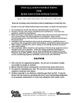
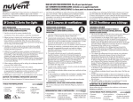
LIMITED WARRANTY
Ventamatic, Ltd. extends this warranty to the original retail purchaser of this fan.
The fan is warranted against defects in materials and workmanship for a period of two (2) years from the
date of original retail purchase. No other parts or components are warranted. There is no warranty for
defects caused by abuse. Repairs or replacement parts supplied under this warranty are warranted only for
the period of this warranty; that is, two (2) years from the date of the original retail purchase of the unit.
In the event of a defect or malfunction, we will replace or repair the defective part or component only and
return the new or repaired part to you freight prepaid. You must bear all other expenses incurred in
obtaining repairs, including labor required for field repair or replacement, and the cost of shipping the
defective part to us. You must also bear the cost of repair to or replacement of any part or component and
the shipping charges incurred for the repair or replacement and return to you of any part or component not
covered by this warranty, including parts or components damaged by you.
The company reserves the right to demand and receive written evidence of the date of purchase before
undertaking to perform its obligations under this warranty. You should, therefore, retain your sales slip and
attach a copy of it to the warranty claim.
In order to obtain the repair or replacement of this unit, you must select one of the following methods:
A.
Return to factory.
Return postage prepaid only the part or component which you believe to be defective to the
following address:
Ventamatic, Ltd
100 Washington Street
Mineral Wells, TX 76067
Complete and enclose a written claim and attach a copy of your sales slip or other proof of
purchase.
B.
Return to retail dealer.
There is no informal dispute settling mechanism available in the event of a controversy involving this
warranty.
Any and all implied warranties which may exist terminate upon the expiration of this warranty one (1) year
from the date of the original retail purchase. Some states do not allow limitations on how long an implied
warranty lasts, so this limitation may not apply to you.
Ventamatic, Ltd. is not liable to you for incidental or consequential damages arising out of a defect or
malfunction of a unit or its installation or out of any alleged breach of this warranty. Some states do not
allow the exclusion or limitation of incidental or consequential damages, so this limitation may not apply to
you.
This warranty gives you specific legal rights and you may also have other rights which may vary from state to
state.
30-INCH PEDESTAL FAN
OPERATING INSTRUCTIONS
MODEL: HVPF 30
CONGRATULATIONS ON YOUR PURCHASE OF THE
MaxxAir™ 30-INCH HIGH VELOCITY PEDESTAL FAN.
With proper care and maintenance the fan will afford
you many years of use. Please read the safety
instructions, and save for future reference.
CAUTION: Read and follow all instructions before
operating fan. Do not use fan if any part is damaged or
missing.
Warning: To reduce risk of fire or electrical shock, do
not use this fan with any solid state speed control
device. This appliance has a 3-prong plug. To reduce
the risk of electrical shock, this plug is intended to fit
in an outlet only one way. If this plug does not fit the
outlet, contact a qualified electrician.
RULES FOR SAFE OPERATION
• Do not insert fingers or any objects through grille guard
when fan is in operation.
• Disconnect fan when moving from one location to
another.
• Disconnect fan when removing guards for cleaning.
• Make sure fan is on a stable, flat surface when in
operation.
• Rain and moisture may create an electrical hazard.
• In order to prevent extension pipe spring from
projecting up, do not release two adjustment screws
(#6) when pipe is all the way down.
VENTAMATIC, LTD. P.O. BOX 728, MINERAL WELLS, TX 76068-0728 • PHONE 800-433-1626 FAX 940-325-9311 • WWW.BVC.COM • E-MAIL: [email protected]
A leader in the ventilation industry for over 60 years, Ventamatic, Ltd. offers a complete line of air movement
products for commercial, industrial, agricultural, and residential use sold under these fine names:
®
®
©2010Ventamatic, Ltd. HVPF30 OPERINSTR
UNPACK YOUR FAN AND CHECK THE CONTENTS (numbers below refer to diagram at right)
• Motor Assembly (10, 11, 12)
• Base Frame Assembly (1, 3)
• Stand Assembly & Spring (2, 5, 6, 7, 8)
• Extension Pipe Assembly (9 )
• Rear / Front Grille & Blade (13, 14, 15, 16, 17, 18)
• Coupler Cover (4)
• Box with Owner’s Manual, Coupler Cover (4), Base screw package (3), Pivot knob and square neck bolt
(10), Adjustment knob (8), Position bolt, spring washer & nut (11), and Grille safety bolt, spring washer
and nut (18) (not shown).
STAND AND BASE ASSEMBLY
1. Put stand assembly with spring (5) on base frame (1) and align holes in the coupler (2) with holes in base
frame (1).
2. Insert screws and spring washers (3) and tighten securely.
3. Slide coupler cover (4) down over the coupler.
STAND ASSEMBLY
1. Make sure spring is in stand assembly (5).
2. Remove two screws (6) from adjuster (7) of extension pipe (9) and insert the adjustment knob (8) and
loosely tighten the adjuster (7).
3. Insert pipe extension (9) into stand pipe (5).
4. Align two holes on stand pipe (5) with holes on adjuster (7), secure adjuster (7) with two screws (6)
removed in Step 2.
5. Adjust extension pipe (9) to desired height.
6. Tighten adjustment knob (8) to set the height.
STAND / MOTOR ASSEMBLY
1. Remove bolt, flat washer, spring washer, nut (for motor position) (11) and square bolt, pivot knob (for angle
setting) (10) from coupler cover package.
2. Align upper round hole on extension pipe assembly (9) with upper round hole in motor flange on motor
assembly (12).
3. Insert bolt and replace flat washer, spring washer and nut (11) removed in Step 1.
4. Adjust tilt to desired position, insert square bolt, two flat washers and pivot knob (10) and tighten pivot knob
(10) to set the angle.
5. Tighten position bolt and nut (11).
REAR GRILLE & BLASE ASSEMBLY
1. Remove four screws, spring washers and flat washers (13) from motor around motor shaft.
2. Align the rear grille (15) over the threaded holes in the motor. (Align the rear grille so that the one small
hole in the outer ring is located to your lower right when facing the fan.)
3. Secure with flat washers, spring washers and screws (13) removed in Step 1.
4. Carefully slide blade assembly (16) over shaft and align inner Allen head screw with slot on motor shaft.
5. Tighten blade assembly (16).
6. CAUTION: Do not alter angle of blades.
FRONT GRILLE ASSEMBLY
1. Open clips in front of grille.
2. Hang front grille (17) on top rib of rear grille (15) by utilizing the U-shaped fixed clip at top of front.
3. Insert and secure safety grille bolt, spring washer and nut (18).
4. Press clips down around front grille to secure.
OPERATION INSTRUCTIONS: To Adjust Airflow Upward or Downward: Loosen position bolt (11), then
loosen pivot knob (10). Tilt motor to desired angle, and firmly tighten pivot knob (10). Firmly tighten pivot
bolt (11). Speed Control: Pull chain on motor assembly to set desired setting (high, medium or low).
CLEANING: WARNING: Unplug from electrical supply source before cleaning. After servicing, any safety
device (including grilles and blades) must be reinstalled or remounted as previously installed.
To clean, use a soft , damp cloth, then wipe dry with a dry cloth. Do not use harmful cleaners. Do not bend blades.
FAN COMPONENTS
1. Base frame
2. Coupler
3. Five (5) screws, flat and spring
washers.
4. Coupler cover
5. Stand assembly with spring
6. Two (2) screws and washers
7. Adjuster
8. Adjustment knob
9. Extension pipe assembly
10. Pivot knob and square-neck bolt
11. Position bolt, spring washer and nut
12. Motor assembly
13. Four (4) screws, flat and spring
washers
14. Allen wrench
15. Rear grille
16. Blade assembly
17. Front grille
18. Small bolt, spring washer
and nut for grille (not shown)
17
PIVOT KNOB
16
15
10
9
8
7
6
5
3
INSET
13
12
11
4
POSITION BOLT,
SPRING WASHER,
& NUT
14
2
1