1
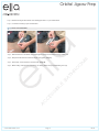
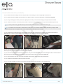
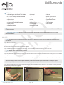
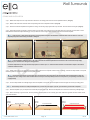
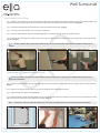
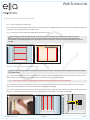
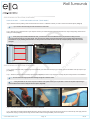
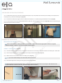
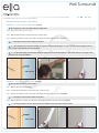
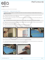
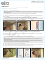
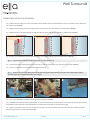
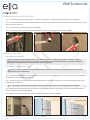
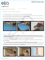
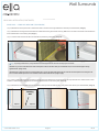
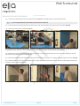
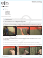
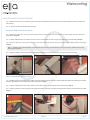
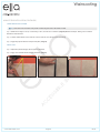
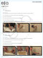
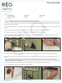
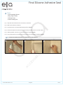
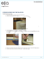
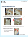
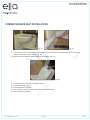
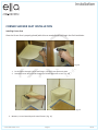
Acrylic Wall Liner Installation Manual Complete / Complete Freedom www.ellasbubbles.com Page 1 08/14 Jigsaw Prep................................................................................6 Shower Bases.............................................................................8 Wall Surrounds......................................................................... 14 Wainscoting.............................................................................30 Accessories..............................................................................34 Final Silicone Adhesive Seal...................................................38 Product Information................................................................39 Installation Tools & Supplies Checklist...................................40 Corner Seat Installation..........................................................42 Warranty...................................................................................49 Warranty Activation Form................................................... 51 www.ellasbubbles.com Page 3 08/14 INSTALLATION / TOOLS & SuPPLIeS LIST Suggested Tool List o Bathtub Liner Template o Expandable Spud Wrench with 1” Combination Wrench o Drain Extractor o Drain Identification Kit o 1- 1 / 2 ” dia. Tub Drain Shoes (Brass and PVC) o 1- 1 / 2 ” dia. Die Cast & Plastic Slip-Joint Nuts & Washers o Tub Drain Shoe Gaskets o Tub Overflow Gaskets (beveled and flat) o 1- 1 / 2 ” dia. Plumb-Quick Rubber Couplings or Boots Drain Snake (hand operated) Plumber’s Putty Butyl Primer Can and Brush Orbital Jigsaw with 6 TPI Blades Sawsall Compound Miter Saw Safety Goggles, Knee Pads and Elastic Back Support Belt o 3 / 8 ” Electric Drill (Cordless 18V) o Dremmel Tool or Roto Zip Tool o Roto Zip Bits for Wood, Plastic and Siding o Heat Gun o Screwdrivers o Utility Knife (Stanley Swivel-Lock) o Sharpie® Felt Pen o Butyl Tape Primer o Rags o Silicone Primer & Cotton Swabs o Denatured Alcohol o 60” Heavy Duty Yardstick o Steel Rafter Square (16”x24”) o Levels (24”, 48” and 72”) o Pliers o Hook Tool o Chisel o 3-Way Razor Scraper o Teflon® Tape o Allen Wrenches o 1- 1 / 4 ” and 2” Hole Saws o Heavy Duty Caulk Gun o 4” Heavy Duty Wall Stripper o o o o o o o www.bciacrylic.com www.ellasbubbles.com ® o 5-in-1 Painters Tool o Drop Light with 6’ Cord or Flash o Work Table o 8” Shower Arms o Pipe Wrench o Adjustable Wrench o Vise Grip o Channel Locks o Handle Puller o Internal Pipe Wrench o Adjustable Slip-Nut Wrench o Tube Cutter o Toilet Tank-to-Bowl Gaskets o Bolt Kits o Wax Mounting Seal o Toilet Supply Line (12” and 16”) o White Soap Dishes o Propane Cylinder, Solder and Flux o Fire Extinguisher o Hand Truck o ½”-thick Sheet Rock o Hammer o Tape Measure (3/4” width) o Duct Tape o 24”x36” Wall Shield o Paper Towels o WD-40® o Garbage Can & Bags o Lava Hand Cleaner (w/ and w/o handle and grout) o Razor Blades o First Aid Kit o Jigsaw Blades o Scratch Remover Kit o Scratch Repair Kit o Printed Cleaning Instructions o Copy of Warranty o 8’ and 50’ Extension Cords o Cutters o Wire Brush o Tool Apron o Drill Bits (Metal and Masonry) o Wall Anchors o Tool Box or 5-Gallon Pail o Suction Cup o Drop Cloths o Shop Vac o 3”-8” Studs o Broom & Dust Pan o Hack Saw o ¼”x20” Drill & Tap o Combo & Handle o Wonder/Pry Bar o File o Sheet Rock Screws (2” and 2-1/2”) o Magnetic Drive Guide o Stud Finder o Nail/Punch Set Page 4 INSTALLATION / TOOLS & SuPPLIeS LIST 4 08/14 Installation - Orbital Jigsaw Prep www.ellasbubbles.com Page 5 08/14 Orbital Jigsaw Prep INSTALLATION / ORBITAL JIGSAW PReP ® Step 1: Measure the length of the bottom of the orbital jigsaw. Add 1” to your measurement. Step 2: Cut Velcro® according to your measurements. Tip: Velcro is recommended. A B Step 3: Place the Velcro® on the bottom of the orbital jigsaw, leaving excess Velcro® hanging off each end. Step 4: Wrap the excess Velcro® around both edges of the jigsaw. (Image A) Step 5: Press firmly, and do the same to the other side. (Image B) Step 6: Before cutting, make sure you are wearing your safety glasses and your orbital setting is on high. www.ellasbubbles.com www.bciacrylic.com Page 6 08/14 INSTALLATION / ORBITAL JIGSAW PReP 12 Installation - Shower Bases www.ellasbubbles.com Page 7 08/14 Shower Bases INSTALLATION / SHOWeRLINeRS & SHOWeR BASeS ® Tip: If you intend to use turnbuckle or crossbar drain on a flat pan liner, you will need to install the adapter plate before you begin to install the liner. If your pan liner has a dimpled recess, you can install the adapter plate after the liner is installed. TuRNBuCkLe dRAIN INSTALLATION Step 1: Dremmel out the drain hole, be sure not to touch the acrylic. (Image J) Step 2: Insert the turnbuckle into the pipe and tighten securely. Step 3: Screw the adapter plate into the existing base with a flat head screwdriver. (Image K) Step 4: Screw the cover on top of the adapter with an allen wrench. (Image L) J L k CROSSBAR dRAIN INSTALATION Step 5: If you are installing this drain on a flat liner, you will have already installed the crossbar under the liner. If installing on a liner with a dimpled recess, place the crossbar on the recessed area. (Image M) Step 6: Place the drain cap over drain hole. Step 7: Secure in place with supplied screw using a flathead screwdriver. (Image N) M www.bciacrylic.com www.ellasbubbles.com N Page 8 INSTALLATION / SHOWeRLINeRS & SHOWeR BASeS 22 08/14 Shower Bases INSTALLATION / SHOWeRLINeRS & SHOWeR BASeS ® SNAP-IN dRAIN INSTALLATION Step 1: Place the cover on the drain and trace the perimeter. Use a dremmel to cut out the hole, then remove the rag from the drain. (Image P) Step 2: Snap the drain into place. (Image Q) O www.bciacrylic.com www.ellasbubbles.com P q Page 9 INSTALLATION / SHOWeRLINeRS & SHOWeR BASeS 23 08/14 Shower Bases INSTALLATION / SHOWeRLINeRS & SHOWeR BASeS ® SHOWER INSTALLATION PAN LINeR PAN INSTALLATION TOOLS Pipe Wrench o Hammer or Sledge o Pry Bar o Spud Wrench o Sharpie® Marker o Notepad o Tape Measure o Drop Cloths o Utility Knife o Step 1: Remove all hardware, including the drain cover. (Image HH) Step 2: Stuff a rag into the drain to keep debris from entering. Step 3: Measure the drain center, from the soap dish wall to the center of the drain and again from the plumbing wall to the center of the drain. Record the measurements. (Image II) Step 4: Use the small wall template to get the angles of the existing shower. Place the template in the corner of the existing base, with one end against the soap dish wall and the other end against the plumbing wall. Set the template to fit and tighten the lock knobs. (Image JJ) HH II JJ Step 5: Carefully remove the template from the shower base. Do not bump the template. If you do, you will need to go back and re-template. Step 6: Measure the height of the threshold by holding a straight edge out from the top of the rail, measure from the floor to the straight edge in 3 or 4 locations. (Image KK) Step 7: Add 3/8” to your height measurements for thickness of acrylic material and adhesives. Record the measurements. Step 8: Transfer measurements. To mark the drain center, place a straight edge in the drain area. Measure from the drain center to the soap dish wall and mark your measurements. Then measure from the drain center to the plumbing wall and mark your measurement. (Image LL) Step 9: Place the template along the marks, and trace the outside of the template. (Image MM) kk www.ellasbubbles.com www.bciacrylic.com LL MM Page 1008/14 INSTALLATION / SHOWeRLINeRS & SHOWeR BASeS 30 Shower Bases INSTALLATION / SHOWeRLINeRS & SHOWeR BASeS ® PAN LINeRLINER INSTALLATION (CONTINued) SHOWER INSTALLATION (CONTINUED) Step 10: Measure and mark the length of the liner, using the width line as a starting point. Use a straight edge to extend the line. Step 11: Measure and mark the height of the threshold in 3 or 4 different locations. Connect the markings with a straight edge. (Image NN) Step 12: Using an orbital jigsaw, carefully cut the liner, supporting the liner with your other hand and keeping your fingers away from the blade. Step 13: Test fit the liner and trim as necessary. Now is the time to check the fit to the existing pan and see if you will need additional layers of tape. Tip: It is okay if there is a tiny gap between the pan liner and existing walls. The walls can be built out to cover the gap. Tip: If you intend to use a turn-buckle or crossbar drain on a flat pan liner, you will need to install the adapter plate before you begin to install the liner. If your pan liner has a dimpled recess, you can install the adapter plate after the liner is installed. Step 14: Install the liner by placing butyl primer along the bottom of the acrylic liner, keeping away from the drain area and the rail of the threshold. (Image OO) Then, prime the rail and the bottom of the existing base, again keeping away from the drain area. (Image PP) NN PP OO Step 15: Place flat tape on top of the primer, setting it paper to paper. Layer the tape as needed to ensure proper contact. Pull the release paper and double-up tape along the perimeter. Remove the release paper. (Image QQ) Step 16: Place round tape along the shelf of the existing base 1/2” away from the wall. (Image RR) Remove the release paper. Place a continuous bead of silicone around the perimeter between the round tape and the wall, and around the drain of the existing base.(Image SS) Step 17: Insert the pan liner, then walk up and down the perimeter to ensure proper contact. Wipe off any excess silicone. Step 18: Install the new drain. Refer to page 22 for proper instructions. Step 19: Once drain is installed, use silicone primer along the perimeter of the pan liner, followed by a color-matching silicone. qq www.ellasbubbles.com www.bciacrylic.com RR SS Page 1108/14 INSTALLATION / SHOWeRLINeRS & SHOWeR BASeS 31 Installation - Wall Surrounds www.ellasbubbles.com Page 1308/14 Wall Surrounds INSTALLATION / WALL SuRROuNdS ® TOOLS o Orbital Jigsaw with Bosch T101 Blade or 10 to 12 Tooth-per-inch Wood Blade o Level o Screwdriver o Suction Cup o Large and Small Wall Templates o Utility Knife o Sharpie® Marker Notepad Tape Measure o Hammer o Chisel o Pipe Wrench o Handle Puller o Work Table o Extension Cords Vacuum Broom and Dust Pan o Garbage Bags o Drywall and Screws o Pliers o Tub Template o Drop Cloths o o o o Tip: It is recommended to install the wall surrounds first and then the bathliner. If you wish to install the bathliner first, please refer to page 11 for proper instructions. SequeNCe OF INSTALLATION: Wall prep first,then install the ceiling panel, then the soap dish wall. Next step is the two side walls and then the bathliner. WALL PReP Tip: If you need to replace the mixer valve, check the codes in the city where you are working. It is quite possible that a plumber may have to do this work. Step 1: Remove the hardware. Step 2: Take off the plumbing fixtures and accessories, which includes the faucet, showerhead, shower grab bars, soap dish and any other fixtures. DO NOT remove the overflow cover. It will be removed later. (Image A) Step 3: If the existing tile does not go all the way to the ceiling, pad out the existing wall above the tile to ensure the wall is flush. Tip: Keep ¼” and ½” drywall sheets in your vehicle. Step 4: To pad the wall, start by measuring the section of the wall that needs to be built-out. Transfer the measurements to the drywall, then cut the drywall according to your measurements. Step 5: Add silicone to the back of the drywall, then press it onto the existing wall. Screw the drywall onto the existing wall to keep it secure. (Image B) Tip: Though drywall is the recommended way to repair a damaged wall, you may need to add additional layers of butyl tape to fir out the wall flush to the existing tile. Please note butyl tape is 1/8” thick, so you will need to assess the proper amount needed to fill the space. Layer the tape one strip on top of another as needed. Pull the release paper as you layer, until you have the exact thickness. Step 6: Clean the existing wall and tub system with industrial strength cleaner and denatured alcohol. Remove all of the old caulk around the perimeter of the bathtub using a safety scraper. (Image C) A www.ellasbubbles.com www.bciacrylic.com B C Page 1408/14 INSTALLATION / WALL SuRROuNdS 37 Wall Surrounds INSTALLATION / WALL SuRROuNdS ® CeILING PANeL INSTALLATION Step 1: Measure the depth from the soap dish wall to where the new ceiling panel will end in three separate locations. (Image D) Step 2: Measure the width from the back wall to the plumbing wall in three separate locations. (Image E) Step 3: Place the small wall template flush against the ceiling, with the long edge against the soap dish wall. This will measure the angles. (Image F) Step 4: Adjust the template accordingly to find the angles for both sides of the ceiling that touch the walls. Note any gaps due to bowed walls or other miscellaneous reasons and adjust accordingly. Once you have the correct angle, tighten the lock-knobs and remove the template. Tip: Keep the clear or blue plastic slip sheeting on all the panels throughout the installation and make marks and cuts with it on. This will help keep the panel from becoming scratched or damaged. d e F Tip: In normal weather conditions, allow a 1/8” gap on all sides for standard expansion and contraction. This can be achieved by simply cutting off your reference lines during the cutting process. In extreme temperatures, the acrylic material may expand or contract up to ¼”. Allow around 20 minutes for the material to adjust to the climate conditions inside the house. Step 5: Identify which end of your panel is the plumbing wall and which is the soap dish wall and mark accordingly. Transfer the depth marks on the panel, measuring back from the bullnose edge to the soap dish wall side. Tip: The measurements will be reversed when they are transferred to the ceiling panel. The sheeted side where the markings are made will actually be the new ceiling surface when installed. Be sure that you accurately identify which end of the panel is your plumbing wall and mark it appropriately. Step 6: Connect depth marks with a straight edge. Place the template on the panel. Use the template to trace the angle onto the acrylic ceiling panel. Tip: Be extremely careful not to bump the template once you have set your angles. If you do, you will need to go back and re-template. Step 7: Hold the template up to your depth line and mark the plumbing wall angle. Remove the template and connect the marks using a straight edge. Step 8: When measuring to get the width, use the plumbing wall template line as a starting point and create the opposite wall line. Double-check your measurements. G H Plumbing Wall Side 1 Soap Dish Wall Side 2 Bullnose Edge www.ellasbubbles.com www.bciacrylic.com Plumbing Wall Side 3 I Soap Dish Wall Side Plumbing Wall Side Soap Dish Wall Side 1 Bullnose Edge Bullnose Edge 2 3 Page 1508/14 INSTALLATION / WALL SuRROuNdS 38 Wall Surrounds INSTALLATION / WALL SuRROuNdS ® CeILING PANeL INSTALLATION (CONTINued) Step 9: Mark the bullnose edge using the bullnose line guide. The bullnose line guide is pre-marked with holes at 1/8” increments for ease of measuring. Locate the appropriate measurement for your bullnose edge. For example, if you are cutting your bullnose edge at 1/4”, then locate the 1/4” hole. Step 10: Place the Sharpie® marker into the appropriate hole and slide the bullnose line guide along the bullnose edge. (Image J) Tip: If there is no tile on the original ceiling, cut the bullnose edge at ¼”. This allows room for 1/8” of acrylic or wall material and 1/8” of tape and adhesive. Step 11: Cut the acrylic according to the measurements. Cut the panel slowly, carefully supporting the panel with your other hand and keeping your fingers clear from the blade. Clean up your scraps as you go. (Image K) Tip: Make sure your jigsaw is properly prepared. See page 9 for instructions. Step 12: Wipe off panel with a terrycloth towel. Test fit the panel, and mark any areas that may need to be trimmed. Tip: Use suction cups to stabilize the panels when test fitting and installing. J k L Step 13: Trim any areas according to the new markings. Test fit again. Continue trimming and re-test fitting as needed. Step 14: Once the ceiling fits, wipe down the existing ceiling with denatured alcohol. Tip: Always use drop cloths to avoid spilling. Step 15: Make reference lines around the ceiling, about 1/2” inside the perimeter. Tap any excess primer off the brush and into the can so it does not drip, then apply butyl primer around the perimeter and from side to side in lines approximately 5 to 9 inches apart. (Image L) Tip: If primer spills, WD-40 can be used to remove it. Step 16: Make sure the primer is dry to the touch and apply the butyl tape on top of the primed areas. Press firmly when installing so the butyl tape does not pull up when you remove the release paper. Tip: If the tape is applied too close to an inside corner and comes in contact with the silicone, it may discolor the finished silicone due to the carbon black in the butyl tape. Step 17: Remove the release paper. Apply the silicone in between the butyl tape in a “Z” pattern, keeping the bead about ¼” thick. Step 18: Clean the back of the panel with denatured alcohol. To ensure proper adhesion throughout, press the ends of the panel near the plumbing and back walls into place first, then work your way towards the center. Make sure to apply even pressure throughout, and push up on the panel to adhere it to the ceiling. Step 19: Remove the slip sheeting and wipe down the panel to ensure it is pressed firmly into place. www.ellasbubbles.com www.bciacrylic.com Page 1608/14 INSTALLATION / WALL SuRROuNdS 39 Wall Surrounds INSTALLATION / WALL SuRROuNdS INSTALLATION / WALL SuRROuNdS ® ® SOAP dISH WALL INSTALLATION SOAP dISH WALL INSTALLATION (CONTINued) Step 1: Install corner reinforcements. Corner reinforcements are part of the triple gasketing system and are used to square up the walls and provide a more permanent seal. Start by measuring from the top of the tub or shower base to the ceiling and record the measurement. (Image M) Step 5: Connect markings with a straight edge. Step 2: Transfer the measurement to the reinforcement. Cut the reinforcement with tin snips. (Image N) Step 6: Measure from the plumbing wall to back wall and record the measurements. (Image S) Transfer these measurements by making three width marks Step 3: Test fit using the corner reinforcement. Trim andstarting re-test fit as necessary. on the panel, the plumbing wall line as the point. Step the reinforcement cleanedge. and prep theT) existing walls using industrial Step4:7:Once Connect the lines with afits, straight (Image This will be the back wall. strength cleaner and denatured alcohol. Step 5: Apply silicone on both sides of the inside corners of the wall in a continuous bead from ceiling to top of tub or shower base. Press reinforcements When your project includes simulated tile walls, you will need to take some additional time to pre-plan before cutting to ensure your into place. (Image O) grout lines will match up on all three panels. This can be done by taking accurate measurements of your soap dish wall and preliminary measurements of your plumbing and back walls. You always want to be sure the full tile is at the top, and equal spacing of tiles are on the left Another continuous bead of silicone will be added on top of the corner reinforcements before final wall installation and after walls are andTip: right. in place. S M T N O Plumbing Wall Side SOAP dISH WALL — LeVeL MeASuRe OPTION SOAP dISH WALL — TeMPLATe MeASuRe OPTION 1 1 2 /4 2 /4 721/2 721/2 There are two measuring options: the template method and the level method. The following is the level method. Please refer to page 36 are two measuring options: the template method and the level method. The following is the template method. Please refer to forThere template method. page 37 for level method. Step 1: Draw a level horizontal line across the soap dish wall, from plumbing wall to back wall. Measure from the horizontal line up to the ceiling in three Step 1: Using the large wall template, place the long edge against the plumbing wall and the short sides against different locations to determine if the ceiling is level. Record the measurements on the existing wall. (Image U) the ceiling and top of tub or shower base. (Image P) Note: If your ceiling is not level, cut the top edge of the wall panel according to the difference in your measurements. Step 2: Check for any gaps due to bowed walls or any other miscellaneous reasons and adjust accordingly. Step 2: Measure from the top of the shower base or tub up to the horizontal line in three different locations. Add these measurements to the measureStep 3: Tighten the large lock-knobs securely. (Image Q) ments you took from the level line to the ceiling, and record them on the existing wall. (Image V) Step 4: Use the template to transfer the measurements onto the soap dish wall panel. Place the template onto the new wall panel, flush with the top ceiling Step 3: Draw a vertical plumb line from the top of the shower base or tub to the ceiling. Measure from the vertical line to the plumbing wall corner reinforceedge, and make three marks along all three sides of the template. (Image R) ments at 3 or 4 different locations to determine if the wall is plumb. Record the measurements on the existing wall. (Image W) Tip: Be extremely careful not to bump the template once you have set your angles. If you do, you will need to go back and re-template. u P www.bciacrylic.com www.ellasbubbles.com www.bciacrylic.com V q 2 2 2 72 / 72 / 72 W R INSTALLATION / WALL SuRROuNdS 41 Page 1708/14 INSTALLATION / WALL SuRROuNdS 40 Wall Surrounds INSTALLATION / WALL SuRROuNdS ® SOAP dISH WALL INSTALLATION (CONTINued) Step 5: Connect markings with a straight edge. Step 6: Measure from the plumbing wall to back wall and record the measurements. (Image S) Transfer these measurements by making three width marks on the panel, using the plumbing wall line as the starting point. Step 7: Connect the lines with a straight edge. (Image T) This will be the back wall. When your project includes simulated tile walls, you will need to take some additional time to pre-plan before cutting to ensure your grout lines will match up on all three panels. This can be done by taking accurate measurements of your soap dish wall and preliminary measurements of your plumbing and back walls. You always want to be sure the full tile is at the top, and equal spacing of tiles are on the left and right. S T Plumbing Wall Side SOAP dISH WALL — LeVeL MeASuRe OPTION 1 1 2 /4 2 /4 721/2 721/2 There are two measuring options: the template method and the level method. The following is the level method. Please refer to page 36 for template method. Step 1: Draw a level horizontal line across the soap dish wall, from plumbing wall to back wall. Measure from the horizontal line up to the ceiling in three different locations to determine if the ceiling is level. Record the measurements on the existing wall. (Image U) Note: If your ceiling is not level, cut the top edge of the wall panel according to the difference in your measurements. Step 2: Measure from the top of the shower base or tub up to the horizontal line in three different locations. Add these measurements to the measurements you took from the level line to the ceiling, and record them on the existing wall. (Image V) Step 3: Draw a vertical plumb line from the top of the shower base or tub to the ceiling. Measure from the vertical line to the plumbing wall corner reinforcements at 3 or 4 different locations to determine if the wall is plumb. Record the measurements on the existing wall. (Image W) u www.ellasbubbles.com www.bciacrylic.com V 2 2 2 72 / 72 / 72 W Page 1808/14 INSTALLATION / WALL SuRROuNdS 41 Wall Surrounds INSTALLATION / WALL SuRROuNdS ® SOAP dISH WALL INSTALLATION (CONTINued) SOAP dISH WALL — LeVeL MeASuRe OPTION (CONTINued) Step 4: Measure from the plumbing wall to the back wall in the same 3 or 4 different locations you used to check if the wall was plumb. (Image X) Tip: Try to measure the walls using the same increments on both sides. Step 5: Write all of your measurements on your notepad. Transfer your measurements to your new wall panel and, using a straight edge, draw lines connecting the marks. (Image Y) Tip: When your project includes simulated tile walls, you will need to take some additional time to pre-plan before cutting to ensure your grout lines will match up on all three panels. This can be done by taking accurate measurements of your soap dish wall and preliminary measurements of your plumbing and back walls. You always want to be sure the full tile is at the top, and equal spacing of tiles are on the left and right. x 2 2 72 / Y 2 72 / 72 1/4 2 52 / 2 2 SOAP dISH WALL INSTALLATION (CONTINued) Step 6: Cut the wall panel slowly, carefully support the panel with your other hand and keeping your fingers clear from the blade. Clean up scraps as you go. (Image Z) Step 7: Test fit the panel and mark necessary adjustments. (Image AA) Use suction cups to assist in handling the panel during the test fit and installation. Tip: Be real careful with larger panels while walking through the customers’ home. Tip: If using simulated tile, the suction cups will not adhere to the panel. Instead, you can pull down a section of the plastic slip sheeting to create handles and use those to help put the wall in place. (Image BB) Z AA BB Step 8: Continue to measure, trim and test fit until you have a desired fit. Step 9: Wipe down the existing wall with denatured alcohol. Tap any excess primer off your brush and into the can so it does not drip, then apply it around the perimeter, staying ½” away from the edge, and from side to side in lines approximately 5 to 9 inches apart. www.ellasbubbles.com www.bciacrylic.com Page 1908/14 INSTALLATION / WALL SuRROuNdS 42 Wall Surrounds INSTALLATION / WALL SuRROuNdS ® SOAP dISH WALL INSTALLATION (CONTINued) Step 10: Make sure the primer is dry to the touch and apply the butyl tape on top of the primed areas. Press firmly when installing so the butyl tape does not pull up when you remove the release paper. (Image CC) Step 11: Remove the release paper. Apply the silicone in between the butyl tape in a “Z” pattern, keeping the bead about ¼” thick. (Image DD) Step 12: Clean the back of the new panel with denatured alcohol or damp cloth. Press the panel firmly into place. (Image EE) Remove the slip sheeting and wipe down the panel to ensure it is secured. CC dd ee PLuMBING WALL INSTALLATION BuLLNOSe edGe FINISHeS There are three options for finishing the ends of your side walls—Option 1: the bullnose edge; Option 2: the use of a tri-guard under the wall panel; or Option 3: the use of a tri-guard over the wall panel. OPTION 1 - Bullnose edge (Image FF) Step 1: If the tile extends to the end of the wall, you will need to remove the last row of tile. Place a drop cloth over the floor and existing tub or shower base. Step 2: Score along the edge of the tile to prevent damage to the existing wall and remaining tiles. (Image GG) Step 3: Break out the first row of tile with a hammer and small pry bar. (Image HH) Tip: If you notice extensive damage to the corner bead, mud and sand the wall. Step 4: The bullnose edge will be cut during the cutting step of plumbing wall installation. Add the existing tile thickness measure to the ¼”, previously mentioned, that allows for an 1/8” of acrylic or wall material and 1/8” of tape and adhesive. (If the tile is 3/8” thick, the bullnose edge would be cut at 5/8”.) FF Sid eW all Pa nal www.ellasbubbles.com www.bciacrylic.com GG HH Bathroom Wall Page 2008/14 INSTALLATION / WALL SuRROuNdS 43 Wall Surrounds INSTALLATION / WALL SuRROuNdS ® PLuMBING WALL INSTALLATION (CONTINued) BuLLNOSe edGe FINISHeS (CONTINued) OPTION 2 – Tri-Guard under Wall Panel (Image II) The tri-guard will need to be installed before the wall panel. Step 1: Measure from the floor to the ceiling. Step 2: Mark the measurement on the tri-guard and cut it with tin snips. Step 3: Place a thick bead of silicone on the inside of the tri-guard and push firmly into place. (Image JJ) Tip: Butyl tape can also be used to adhere the tri-guard. Tip: When measuring for your wall panel width, you will want to keep the bullnose edge a 1/8” to a ¼” from the return wall edge so there is a place to apply a finishing bead of silicone. (Image KK) Tip: Cut the bullnose edge on the wall panel during the cutting step. Cut the bullnose edge at ¼”. This allows room for 1/8” of acrylic or wall material and 1/8” of tape and adhesive. II JJ Sid eW all Pa nel kk Tri-Guard (under wall panel) Bathroom Wall OPTION 3 – Tri-Guard Over Wall Panel (Image LL) This will be done after the wall is installed. Step 1: Measure from the floor to the ceiling. Step 2: Transfer the measurements to the tri-guard, then cut with tin snips. Step 3: Place a thick bead of silicone on the inside of the tri-guard and push firmly into place. (Image MM) Tip: Butyl tape can also be used to adhere the tri-guard. Step 4: When installation is complete, you will apply a finishing bead of silicone along the tri-guard. (Image NN) Tip: The tri-guard comes in all color options as well as two different sizes. See product catalog for details. LL Sid eW all Pa nel www.ellasbubbles.com www.bciacrylic.com MM NN Tri-Guard (over wall panel) Bathroom Wall Page 2108/14 INSTALLATION / WALL SuRROuNdS 44 Wall Surrounds INSTALLATION / WALL SuRROuNdS ® PLuMBING WALL INSTALLATION (CONTINued) PLuMBING WALL — TeMPLATe MeASuRe OPTION There are two measuring options: the template method and the level method. The following is the template method. Please refer to page 42 for level method. Step 1: Using the large wall template, place the template on the plumbing wall, with the long edge against the soap dish wall and the short sides tight against the ceiling and top of tub or shower base. (Image OO) Step 2: Check for any gaps due to bowed walls or other miscellaneous reasons, and adjust accordingly. Once you have set the angles, tighten the lockknobs and remove the template. Tip: Be extremely careful not to bump the template once you’ve set your angles. If you do, you will need to go back and re-template. Step 3: Measure from the soap dish wall side out to the location where the bullnose edge or tri-guard will end. In most cases, this location should be at least ¼” past the end of the existing tile. (Image PP) Step 4: Make sure that plumbing wall bullnose edge matches up to the bullnose edge on the ceiling. Step 5: Mark these measurements on your wall panel and connect the marks using a straight edge.(Image QQ) OO PP qq Step 6: Place the wall template onto the new wall panel, flush with the top ceiling edge. Hold the template up to this depth line to mark the top and bottom angles of the plumbing wall. Remove the template and connect the marks using a straight edge. (Image RR) Step 7: Mark the bullnose edge using the bullnose line guide. Locate the appropriate measurement for your bullnose edge. Place your Sharpie® marker into the appropriate hole and slide the bullnose line guide along the bullnose edge. (Image SS) RR www.ellasbubbles.com www.bciacrylic.com SS Page 2208/14 INSTALLATION / WALL SuRROuNdS 45 Wall Surrounds INSTALLATION / WALL SuRROuNdS ® PLuMBING WALL INSTALLATION (CONTINued) PLuMBING WALL — LeVeL MeASuRe OPTION There are two measuring options: the template method and the level method. The following is the level method. Please refer to page 41 for template method. Step 1: Draw a level horizontal line across the plumbing wall, from soap dish wall to outside edge of plumbing wall. (Image TT) Step 2: Measure from the horizontal line up to the ceiling in three different locations to determine if the ceiling is level. Record the measurements on the existing wall. (Image UU) Note: If your ceiling is not level, cut the top edge of the wall panel according to the difference in your measurements. Step 3: Measure from the top of the tub or shower base up to your horizontal level line in 3 different locations. Add these measurements to your measurements from the level line to the ceiling, and record them on the existing wall. (Image VV) TT uu VV Step 4: Measure from the top of the tub or shower base down to the floor for the leg measurement. Record your measurement. (Image WW) Step 5: Measure from the edge of the plumbing wall to the outside of the tub to get the width of the leg. Make sure to account for the radius of the tub. Record these measurements on the existing wall. Tip: If your leg is less than 2”, it may tend to bow-out during the test fit. There are two ways you can fix this. OPTIOn 1: If you have removed the floor trim and the panel comes to the floor when you reinstall the trim, it can be used to support the leg against the tub. (Image XX left) OPTIOn 2: Drill a pilot hole and use a small finishing nail to secure the panel tight against the tub. The nail should be placed close enough to the tub so it will be hidden by the liner once installed or when sealed with silicone. (Image XX right) Step 6: Check to make sure the tub skirt or shower base is plumb using a small level. Step 7: Draw a vertical plumb line from the ceiling to the top of the tub or shower base. Measure from the vertical line to the soap dish wall corner reinforcement in three locations to determine if the wall is plumb. Record these measurements on the existing wall. Step 8: Measure from the soap dish wall out to the location where you want the bullnose edge or tri-guard to end. Record your measurements. (Image YY) WW xx YY Finishing Nail Option 1 www.ellasbubbles.com www.bciacrylic.com Option 2 Page 2308/14 INSTALLATION / WALL SuRROuNdS 46 Wall Surrounds INSTALLATION / WALL SuRROuNdS ® PLuMBING WALL INSTALLATION (CONTINued) Step 1: Measure from the ceiling to the center of the shower arm hole. Measure from the soap dish wall to the center of the shower arm hole. Write down your measurements. (Image A) Step 2: Measure from the ceiling and from the soap dish wall to the center of the mixer valve. Record your measurements. (Image B) Step 3: Measure down from the ceiling and from the soap dish wall to the center of the tub spout. Record your measurements. (Image C) A B C Step 4: Transfer your measurements onto the new sheet of acrylic. Use a straight edge to connect the measurements. (Image D) Tip: If you are using simulated tile, double check that the grout lines will match up. Step 5: Cut the panel slowly, carefully supporting your panel with your other hand and keeping your fingers clear from the blade. (Image E) Step 6: Use a 1¼” hole saw to cut out holes for all three hardware openings. Tip: The mixer valve hole will probably need to be enlarged. Use a jigsaw to enlarge the hole for the mixer valve, making it large enough to get at the screws, but not bigger than the valve cover. (Image F) d e F Step 7: Test fit your panel. Make sure that your plumbing holes line up and trim as needed. Step 8: Wipe down the existing wall with denatured alcohol. Tap any excess primer off your brush and into the can so it does not drip, then apply it around the perimeter and from side to side in lines approximately 5 to 9 inches apart. Keep primer ½ inch away from the edge. Step 9: Make sure the primer is dry to the touch and apply the butyl tape on top of the primed areas. Be sure to press firmly when installing so the butyl tape does not pull up when you remove the release paper. www.ellasbubbles.com www.bciacrylic.com Page 2408/14 INSTALLATION / WALL SuRROuNdS 47 Wall Surrounds INSTALLATION / WALL SuRROuNdS ® PLuMBING WALL INSTALLATION (CONTINued) Step 10: Remove the release paper. Apply the silicone in between the butyl tape in a “Z” pattern, keeping the bead about ¼” thick. (Image G) Step 11: Clean the back of the new panel with denatured alcohol or damp cloth. Press the panel firmly into place. Remove the slip sheeting and wipe down the panel to ensure it’s secured. Step 12: Attach the plumbing fixtures with Teflon® tape. (Image H) Step 13: Use silicone to fill in the gaps before the escutcheon plates are affixed. Seal behind and around the fixtures. (Image I) G H I BACk WALL INSTALLATION BuLLNOSe edGe FINISHeS There are three options for finishing the ends of your side walls—Option 1: the bullnose edge; Option 2: the use of a tri-guard under the wall panel; or Option 3: the use of a tri-guard over the wall panel. You should finish the edge as you did when installing the plumbing wall. See pages 39 and 40 for directions on the three finishing options. BACk WALL —TeMPLATe MeASuRe There are two measuring options: the template method and the level method. The following is the template method. Please refer to page 45 for the back wall level method. Step 1: Using the large wall template, place the template on the back wall, with the long edge against the soap dish wall and the short sides tight against the ceiling and top of tub or shower base. (Image J) Step 2: Check for any gaps due to bowed walls or other miscellaneous reasons, and adjust accordingly. Once you have set the angles, tighten the lockknobs and remove the template. Tip: Be extremely careful not to bump the template once you’ve set your angles. If you do, you will need to go back and re-template. Step 3: Measure from the soap dish wall side out to the location where the bullnose edge or tri-guard will end. In most cases, this location should be at least ¼” past the end of the existing tile. (Image K) Step 4: Make sure that back wall bullnose edge matches up to the bullnose edge on the ceiling. (Image L) J k L Installed Ceiling Panel Back Wall www.ellasbubbles.com www.bciacrylic.com Page 2508/14 INSTALLATION / WALL SuRROuNdS 48 Wall Surrounds INSTALLATION / WALL SuRROuNdS ® BACk WALL INSTALLATION (CONTINued) BACk WALL —TeMPLATe MeASuRe (CONTINued) Step 5: Mark these measurements on your wall panel and connect the marks using a straight edge. (Image M) Step 6: Place the wall template onto the new wall panel, flush with the top ceiling edge. Hold the template up to this depth line to mark the top and bottom angles of the back wall. Remove the template and connect the marks using a straight edge. (Image N) Step 7: Mark the bullnose edge using the bullnose line guide. Locate the appropriate measurement for your bullnose edge. Place your Sharpie® marker into the appropriate hole and slide the bullnose line guide along the bullnose edge. M N O BACk WALL – LeVeL MeASuRe There are two measuring options: the template method and the level method. The following is the level method. Please refer to page 44 for the back wall template method. Step 1: Draw a level horizontal line across the back wall, from soap dish wall to outside edge of back wall. (Image P) Step 2: Measure from the horizontal line up to the ceiling in three different locations to determine if the ceiling is level. Record the measurements on the existing wall. (Image Q) Note: If your ceiling is not level, cut the top edge of the wall panel according to the difference in your measurements. Step 3: Measure from the top of the tub or shower base up to your horizontal level line in 3 different locations. Add these measurements to your measurements from the level line to the ceiling, and record them on the existing wall. (Image R) P www.ellasbubbles.com www.bciacrylic.com q R Page 2608/14 INSTALLATION / WALL SuRROuNdS 49 Wall Surrounds INSTALLATION / WALL SuRROuNdS ® BACk WALL INSTALLATION (CONTINued) BACk WALL —TeMPLATe MeASuRe (CONTINued) Step 4: Measure from the top of the tub or shower base down to the floor for the leg measurement. Record your measurement. (Image S) Step 5: Measure from the edge of the back wall to the outside of the tub to get the width of the leg. Make sure to account for the radius of the tub. Record these measurements on the existing wall. (Image T) Step 6: Check to make sure the tub skirt or shower base is plumb using a small level. (Image U) S T u Tip: If your leg is less than 2”, it may tend to bow out during the test fit. There are two ways you can fix this. OPTIOn 1: If you have removed the floor trim and the panel comes to the floor when you reinstall the trim, it can be used to support the leg against the tub. (Image S left) OPTIOn 2: Drill a pilot hole and use a small finishing nail to secure the panel tight against the tub. The nail should be placed close enough to the tub so it will be hidden by the liner once installed or when sealed with silicone. (Image S right) Step 7: Draw a vertical plumb line from the ceiling to the top of the tub. Measure from the vertical line to the soap dish wall corner reinforcement in three locations to determine if the wall is plumb. Record these measurements on the existing wall. (Image W) Step 8: Measure from the soap dish wall out to the location where you want the bullnose edge or tri-guard to end. Record your measurements. (Image X) W x Finishing Nail Option 1 www.ellasbubbles.com www.bciacrylic.com Option 2 Page 2708/14 INSTALLATION / WALL SuRROuNdS 50 Wall Surrounds INSTALLATION / WALL SuRROuNdS ® BACk WALL INSTALLATION (CONTINued) Step 1: Transfer your measurements onto the new sheet of acrylic. (Image AA) Use a straight edge to connect the measurements. Tip: If you are using simulated tile, double check that the grout lines will match up. Step 2: Cut the panel slowly, carefully supporting your panel with your other hand and keeping your fingers clear from the blade. (Image BB) Step 3: Test fit your panel and trim as needed. (Image CC) AA BB CC Step 4: Wipe down the existing wall with denatured alcohol. Tap any excess primer off your brush and into the can so it does not drip, then apply it around the perimeter and from side to side in lines approximately 5 to 9 inches apart. Keep primer ½“ away from the edge. (Image DD) Step 5: Make sure the primer is dry to the touch and apply the butyl tape on top of the primed areas. Be sure to press firmly when installing so the butyl tape does not pull up when you remove the release paper. Step 6: Remove the release paper from the butyl tape. Apply the silicone in between the butyl tape in a “Z” pattern, keeping the bead about ¼” thick. (Image EE) Step 7: Clean the back of the new panel with denatured alcohol or damp cloth. Press the panel firmly into place. Remove the slip sheeting and wipe down the panel to ensure it is secured. (Image FF) dd www.ellasbubbles.com www.bciacrylic.com ee FF Page 2808/14 INSTALLATION / WALL SuRROuNdS 51 Installation - Wainscoting www.ellasbubbles.com Page 2908/14 Wainscoting INSTALLATION / WAINSCOTING ® TOOLS Tin Snips Tape Measure o Straight Edge o Orbital Jigsaw o Sharpie® Marker o o WAINSCOTING INSTALLATION Step 1: Ask the customer how high up the wall they want the wainscoting to end. (Image A) Tip: Height cannot pass 59”. Step 2: Draw a level horizontal line across the wall 1” below the desired location. (Image B) Tip: If there is existing tile on the wall, and the top of the existing tile is level, you can use that as your horizontal line. Step 3: Measure down from the horizontal line to the floor in 3 or 4 different locations. Add 1” to the measurements. (Image C) Record the measurements. A B C Step 4: Draw a level vertical line from your horizontal line to the floor. Measure from the vertical line to one end of the wall in 3 or 4 different locations. Record the measurements. (Image D) Step 5: Cut the panel, carefully supporting the panel with your other hand while keeping your fingers clear from the blade. Keep slip sheet on to prevent any scrapes or scratches. Step 6: Test fit the panel, and make necessary adjustments. Step 7: Prime along the border of the existing wall, staying ½” away from the edge. Place primer in vertical lines approximately 9” apart. (Image E) Step 8: Allow primer to dry. Cover the primer with butyl tape and remove the release paper. Place silicone sealant between the lines in a “Z” pattern. (Image F) d www.ellasbubbles.com www.bciacrylic.com e F Page 3008/14 INSTALLATION / WAINSCOTING 62 Wainscoting INSTALLATION / WAINSCOTING ® WAINSCOTING INSTALLATION (CONTINued) Step 9: Wipe down the back of your wainscoting with a clean rag and denatured alcohol. Place one end of the panel against the wall first and press the rest into place. Step 10: Remove the slip sheet and wipe down the panel. OuTSIde CORNeR TRIM INSTALLATION Step 1: Measure the height first, from top of wainscoting to the floor at each corner. Add 1/8” to account for extra material at the top. Record the measurement. (Image G) Step 2: Transfer measurement to the outside corner trim. Cut the corner trim with tin snips, being very careful to keep your hand steady. (Image H) Step 3: Test fit for the return. The top piece should sit on top of the wainscoting. Hold the corner piece to the adjacent edge and scribe accordingly. (Image G) Tip: Installing corners varies depending on the bathroom. Be sure to take your time because you may have to test fit, measure and cut a few times to get the perfect fit. Step 4: Install the outside corner piece by stretching and applying butyl tape on the inside of the piece. Push the corner piece into place. G H I INSIde CORNeR TRIM INSTALLATION Step 1: Measure the height of the wainscoting, adding 1/8” for the material at the top of the trim. Hold a straight edge against the wainscoting to measure the depth, again adding 1/8” for material. Record the measurements. (Image J) Step 2: Transfer measurements to the inside corner trim and cut with tin snips. Test-fit the piece and trim if necessary. (Image K) Step 3: Apply the butyl tape on the inside corner trim just like the outside corner trim. Apply tape to both sides of the inside corner trim and push into place. (Image L) J www.ellasbubbles.com www.bciacrylic.com k L Page 3108/14 INSTALLATION / WAINSCOTING 63 Wainscoting INSTALLATION / WAINSCOTING ® WAINSCOTING INSTALLATION (CONTINued) SeAM TRIM INSTALLATION Tip: Seam trim covers the seam of two pieces of wainscoting that meet in the middle of a wall. Step 1: Measure the height, from top of wainscoting to floor, and add 1/8” for material. (Image M) Measure the depth, adding 1/8” for material. Record the measurements. Step 2: Transfer measurements to the seam trim. Cut the seam trim, then test fit and trim accordingly. Step 3: Apply butyl tape to seam trim and push into place. (Image N) FINAL SeAL Step 1: Wipe down panels and apply silicone primer to all seams. Step 2: Apply color-matched silicone sealant to all seams. (Image O) M www.ellasbubbles.com www.bciacrylic.com N O Page 3208/14 INSTALLATION / WAINSCOTING 64 Installation - Accessories www.ellasbubbles.com Page 3308/14 Accessories INSTALLATION / ACCeSSORIeS ® CORNeR CAddY TOOLS o White Butyl Tape INSTALLATION Step 1: Apply white butyl tape along the back perimeter of the caddy, making sure to stay about ½” away from the edge. Step 2: Place a ball of butyl tape inside the caddy to add extra support. (Image A) Step 3: Remove the release paper. Step 4: Ask the homeowner where they want the caddy installed. (Image B) Step 5: Push the caddy into place. (Image C) Tip: There is a top and bottom side to the caddy. Be sure it is installed correctly. A B C SOAP dISH TOOLS o White Butyl Tape INSTALLATION Step 1: Apply white butyl tape around the back perimeter of the soap dish, staying ½” away from the edge. (Image D) Step 2: Place a ball of butyl tape inside the shelf to add extra support. (Image E) Step 3: Remove the release paper. Step 4: Ask the customer where they want the soap dish installed. (Image F) Step 5: Push the soap dish into place. d www.ellasbubbles.com www.bciacrylic.com e F Page 3408/14 INSTALLATION / ACCeSSORIeS 66 Accessories INSTALLATION / ACCeSSORIeS ® ReCeSSed SOAP dISH TOOLS Tape Measure o Sharpie® Marker o o o Hole Saw Jigsaw Butyl Tape o Level o INSTALLATION Note: Installing a recessed soap dish is done during the soap dish wall installation. Step 1: If there is an existing soap dish opening, measure from the plumbing wall to the beginning of the soap dish opening and from the top of the tub up to the bottom of the soap dish opening. If there is not an existing soap dish, or the customer would like it relocated, take the same aforementioned measurements once the customer has approved a location. Step 2: Hold the soap dish on the existing wall in the proper position, and trace the opening with a Sharpie® marker. (Image G) Step 3: Make a rough opening, large enough to accommodate the new soap dish in the marked location. (Image H) Step 4: Transfer the pre-recorded measurements onto the new wall and draw a box to accept the new recessed soap dish, typically 5” square. Double check your position measurements. (Image I) G H I Step 5: Make the appropriate cuts to the new wall. Step 6: Drill a starter hole with a 1¼” hole saw in a corner of the marked opening to prevent cracking. Cut out the opening with a jigsaw. (Image J) Step 7: Test fit the soap dish cutout to the rough opening and make sure it’s a good fit. Proceed using standard wall surround installation instructions on page 32. Tip: When installing a wall with a soap dish cutout, prime and add butyl tape around the perimeter of the opening in addition to the vertical strips normally applied to the wall. (Image K) Step 8: Place butyl tape around the back perimeter of the soap dish, staying ½” away from the edge. Remove the release paper. Step 9: Push soap dish into place and check to make sure it is level. (Image L) J www.ellasbubbles.com www.bciacrylic.com k L Page 3508/14 INSTALLATION / ACCeSSORIeS 67 Accessories INSTALLATION / ACCeSSORIeS ® SHAVING STANd TOOLS White Butyl Tape o Sharpie® Marker o Level o INSTALLATION Step 1: Ask the homeowner where they would like the shaving stand to be installed, and mark the location. (Image M) Step 2: Apply butyl tape to the back of the shaving stand. Step 3: Remove release paper and continue to add layers of butyl tape as needed to ensure proper contact with wall. (Image N) Step 4: Use the marks to align the shaving stand and push into place. Check to make sure it is level. (Image O) M www.ellasbubbles.com www.bciacrylic.com N O Page 3608/14 INSTALLATION / ACCeSSORIeS 68 Installation - Final Silicone Adhesive Seal www.ellasbubbles.com Page 3708/14 Final Silicone Adhesive Seal INSTALLATION / FINAL SILICONe AdHeSIVe SeAL ® TOOLS o o o o Color-matching Silicone Rag / Paper Towels Silicone Primer Caulk Finishing Tool Step 1: Wipe down all the walls and the liner as well as any accessories. Step 2: Make sure the bathroom is dust free. Step 3: Use silicone primer on all seams before applying silicone. (Image A) Step 4: Check that wall panels and accessories are pressed firmly into place and have not moved or lifted. Step 5: Seal the perimeter of the liner and accessories, and fill in all gaps. (Image B) Step 6: Using a caulk finishing tool to clean off any excess silicone and smooth with your fingertip. (Image C) Tip: It’s best to do a small area at a time so the silicone does not start to skin over. A www.ellasbubbles.com www.bciacrylic.com B C Page 3808/14 INSTALLATION / FINAL SILICONe AdHeSIVe SeAL 73 Product Information BCI® ACRYLIC DEALER TIPS & TECHNIQUES PRODUCT INFORMATION RECOMMENDED ACRYLIC CLEANERS Use only cleaning products whose labels state that they are SAFE FOR ACRYLIC. Always test products on a small area of skirt before applying to complete bath area. SCRUB FREE FORMULA 409 BATHROOM DUCK SCRUB FREE W/OXY LEMON SCENT ZEP SHOWER TUB & TILE GREENWORKS NATURAL ALL PURPOSE CLEANER KABOOM SHOWER TUB & TILE CLEANER SEVENTH GENERATION SHOWER CLEANER – NATURAL CITRUS DO NOT USE the following on your ACRYLIC Bath System The use of the following chemicals will cause a dull surface or chemical cracks. The use of these products will VOID YOUR WARRANTY. DOW SCRUBBING BUBBLES ABRASIVE CLEANERS AJAX COMET FANTISTIK TILEX SOFT SCRUB MR. CLEAN NAIL POLISH REMOVER SCOURING PADS AMMONIA TOUGH ACT POWDER OR CRYSTAL DRAIN CLEANERS GREENWORKS BATHROOM CLEANER SCRUB FREE W/BLEACH SEVENTH GENERATION BATHROOM CLEANER – REGULAR MAGIC ERASER 1 www.ellasbubbles.com BCI® ACRYLIC DEALER TIPS & TECHNIQUES v.2 | PRODUCT INFORMATION Page 3908/14 Installation Tools & Supplies Checklist Installation Below is a list of suggested tools and supplies for installing BCI Acrylic products. Installation Tools BCI® Tools (refer to Price Guide for ordering information) Tub Template Hook Tool 3‐Way Razor Scraper Drain ID Kit Drain Extractor Suction Cups Expandable Spud Wrench w/1” Scratch Repair Kit BCI ACRYLIC DEALER TIPS & TECHNIQUES combination Wrench Butyl Tape Primer (quart or gallon) Scratch Remover Kit Installation Tools & Supplies Checklist Silicone Primer (13.5 oz.) Butyl Primer Can & Brush INSTALLATION Overflow Gasket Large Wall Template Small Wall Template Below is a list of suggested tools and supplies for installing BCI Acrylic products. Installation Tools Standard Tools BCI® Tools REQUIRED (refer to Price Guide for ordering information) Tub Template Tape Measure (3/4” width) Drain ID Kit Safety goggles, knee pads & elastic back support belt Expandable Spud Wrench w/1” combination Wrench Levels (24”, 48”, 72”) Dremmel® Tool or Roto Zip® Scratch Remover Kit Tool Silicone Primer (13.5 oz.) 25’ and 50’ Extension Cords Hook Tool 60” Metal Ruler Drain Extractor Hammer Scratch Repair Kit Pliers Butyl Tape Primer (quart or Allen Wrenches gallon) SUGGESTED 3‐Way Razor Scraper Wire Brush or Paint Scraper Suction Cups Handle Puller Overflow Gasket Nail/Punch Set Large Wall Template Chisel Butyl Primer Can & Brush Hole Saw Kit Small Wall Template Hack saw Heavy Duty Caulk Gun Screw drivers Duct Tape Orbital Jigsaw w/ 10 TPI blades Crescent Wrench File Standard Tools Drill bits (metal and masonry) REQUIRED Teflon Tape Wall anchors and Non‐corrosive Tape Measure (3/4” width) Screws Safety goggles, knee pads & 3/8” Electric Drill/Cordless Drill elastic back support belt 18V Levels (24”, 48”, 72”) 1 5/8” and 3” Screws Dremmel® Tool or Roto Zip® Tool Utility Knife 25’ and 50’ Extension Cords Channel Locks Heavy Duty Caulk Gun Pipe Wrench Orbital Jigsaw w/ 10 TPI blades Sawzall Drill bits (metal and masonry) 1‐1/2” dia. Die cast & plastic 60” Metal Ruler slip‐joints & washers Hammer 1/4” X 20 Drill & Tap Combo & Handle Pliers Steel Rafter Square (16”x24”) Allen Wrenches Pipe cutters (good quality) Hole Saw Kit Thread Compound Screw drivers Tub Drain Shoe Gaskets Crescent Wrench Teflon Tape Wall anchors and Non‐corrosive Screws 3/8” Electric Drill/Cordless Drill 18V 1‐1/2” dia. Die cast & plastic slip‐joints & washers 1/4” X 20 Drill & Tap Combo & Handle 1 5/8” and 3” Screws Steel Rafter Square (16”x24”) 1 Utility Knife Roto Zip Bits for wood, plastic & SUGGESTED siding Wire Brush or Paint Scraper Compound Miter Saw Handle Puller Stud Finder Nail/Punch Set Adjustable Slip‐Nut Wrench Chisel Roto Zip® bits for wood, plastic & siding Hack saw 3 lb. Sledge Hammer Duct Tape Drain Snake (hand‐operated) File Roto Zip Bits for wood, plastic & siding Compound Miter Saw Stud Finder Adjustable Slip‐Nut Wrench Roto Zip® bits for wood, plastic & BCI ACRYLIC DEALER TIPS & TECHNIQUES | INSTALLATION [Tools & Supplies v.1] Pipe cutters (good quality) siding Channel Locks Thread Compound 3 lb. Sledge Hammer Pipe Wrench Tub Drain Shoe Gaskets Drain Snake (hand‐operated) Sawzall www.ellasbubbles.com Page 4008/14 Installation INSTALLATION BCI ACRYLIC DEALER TIPS & TECHNIQUES Installation Tools & Supplies Checklist Installation Tools (cont.) Other Tools/Items REQUIRED SUGGESTED Drop cloths Drop Light w/6’ cord or flashlight Folding Saw horses; 1 sheet 4’x8’x3/4” plywood (cutting table) Shop Vac Magnetic Drive Guide Heat Gun Sealant Finisher Propane cylinder, Solder & Flux Fire Extinguisher 1/2” Thick Green Board/Sheet Rock 24” X 36” Wall Shield (scrap piece of acrylic to protect wall when installing Bathliner) Wonder/Pry Bar Tool Box or 5 Gallon Pail 3‐8’ Studs Supplies REQUIRED SUGGESTED Sharpie® Marker Razor Blades Broom & Dust Pan Q‐tips® First Aid Kit Lava Hand cleaner Soft, clean rags Denatured Alcohol Garbage Can or Trash Bags WD‐40® Paper Towels (Bounty® Select‐A‐ Size) In‐Home Measuring Kit BCI Sales Kit (Sales Presentation Book, Material Sample Book, Sales Bag, including Simulated Tile Wall Samples) BCI® Acrylic Product brochures Printed Cleaning Instructions (Approved Cleaners) Micro‐Tub BCI® 3 Piece Measuring Tool Corner Reinforcement (Trim) Sample Before & After Photos of completed jobs Digital Camera References from completed jobs Tape Measure Pen/Sharpie® Marker Contracts 48” Level New Drain Warranty for customer to review www.ellasbubbles.com Page 4108/14 Installation INSTALLATION BCI ACRYLIC DEALER TIPS & TECHNIQUES CORNER SHOWER SEAT INSTALLATION Follow the steps below when installing a BCI® Acrylic Corner Shower Seat. NOTE: The Shower Base is installed before the Corner Shower Seat. The Wall Surrounds are installed after the Corner Shower Seat. 1. Shower Base installed 2. Corner Shower Seat installed 3. Wall Surrounds installed Tools/Supplies 2” x 4” ‘s Level Drill Screwdrivers Jigsaw Sharpie® Marker Tape Measure Broom, dust pan Garbage bags Drywall Drywall screws Shims Drop cloths Dust mask Safety glasses, gloves Initial Steps 1. 2. 3. 4. 5. Install the Shower Base per instructions. (See BCI® Installation Manual for more information.) Place cardboard in bottom of Shower Base for protection. Check to make sure you have the right order for the right customer. Double check the color of the Corner Shower Seat. The Corner Seat is typically installed opposite of the plumbing. CORNER SEAT DETAILS: Seat Area = 16” x 16” Corner Seat piece extends out 19 ¼” on both the left and right side. (Fig. 1) Can hold up to 300 pounds. Has been tested and approved by NAHB Research Center 19 ¼” 19 ¼” 16” x 16” Fig. 1 1 www.ellasbubbles.com BCI ACRYLIC DEALER TIPS & TECHNIQUES | CORNER SHOWER SEAT INSTALLATION v.2 Page 4208/14 Installation INSTALLATION BCI ACRYLIC DEALER TIPS & TECHNIQUES CORNER SHOWER SEAT INSTALLATION 17” 17” Fig. 2 Set Frame for Corner Shower Seat 1. Measure roughly 17” out from inside corner for outside edges of Corner Seat. (Fig. 2) a. This measurement may be different depending on the studs already in place. 2. At the appropriate measurement, add additional frame/studs to inside wall area for seat as needed. (Fig. 2) 3. Add 2” x 4” as needed for cross beams. Initial Cutting The Corner Seat includes flanges and sprayfoam on the back for stability. (Fig. 3) Fig. 3 2 www.ellasbubbles.com BCI ACRYLIC DEALER TIPS & TECHNIQUES | CORNER SHOWER SEAT INSTALLATION v.2 Page 4308/14 Installation INSTALLATION BCI ACRYLIC DEALER TIPS & TECHNIQUES CORNER SHOWER SEAT INSTALLATION Trim & Test Fit Corner Seat 1. Place Corner Seat into shower area to assess placement. 2. Check to see if the Seat is level. (Fig. 4) Fig. 4 3. View bottom Corner Seat and how it aligns with shower base. For Corner Seat to sit flush against the shower base, the bottom corners and bottom edge will need to be trimmed. Fig. 5 Fig. 6 4. Measure the width of shower base flange. The Corner Seat must sit flush on top of this flange. (Fig. 5) 5. Transfer measurement to bottom of Corner Seat – on both sides. (Fig. 6) www.ellasbubbles.com Page 4408/14 Installation INSTALLATION BCI ACRYLIC DEALER TIPS & TECHNIQUES CORNER SHOWER SEAT INSTALLATION Fig. 7 6. Connect measurement lines with straight edge on bottom of Corner Seat. (Fig. 7) Fig. 8 Fig. 9 7. Trim bottom of Corner Seat with jigsaw. (Fig. 8) Cut sprayfoam backing as needed when trimming. 8. Notice the bottom corners and how they are notched (circled) to fit on top of the shower base. (Fig. 9, Fig. 10) Fig. 9 shows the Corner Seat upside down. Fig. 10 shows the Corner Seat test fitted on top of the shower base. Fig. 10 NOTCH CLOSE‐UP www.ellasbubbles.com 4 Page 4508/14 BCI ACRYLIC DEALER TIPS & TECHNIQUES | CORNER SHOWER SEAT INSTALLATION v.2 Installation INSTALLATION BCI ACRYLIC DEALER TIPS & TECHNIQUES CORNER SHOWER SEAT INSTALLATION Fig. 11 Fig. 12 9. Test fit Corner Seat. View how the bottom of the Corner Seat fits on top of the Shower Base. Check to make sure the Corner Seat is level. (Fig. 11) 10. Mark the bottom where the Seat needs to be trimmed. (Fig. 12) Fig. 13 11. 12. 13. 14. 15. Trim bottom of Corner Seat as needed. (Fig. 13) Test fit Corner Seat again. Trim and test fit as needed. Use a level to ensure the Corner Seat will be installed properly. Shim and level as needed. www.ellasbubbles.com Page 4608/14 Installation BCI ACRYLIC DEALER TIPS & TECHNIQUES INSTALLATION CORNER SHOWER SEAT INSTALLATION Installing Corner Seat Once the Corner Seat is properly placed (with shims as needed) and level, begin the final installation. Fig. 14 1. Pre‐drill holes through Corner Seat flanges, into the frame previously built. 2. Attached Corner Seat to studs through pre‐drilled holes with screws. (Fig. 14) Fig. 15 3. Measure, cut and attach drywall to wall frames. (Fig. 15) www.ellasbubbles.com Page 4708/14 Installation BCI ACRYLIC DEALER TIPS & TECHNIQUES INSTALLATION CORNER SHOWER SEAT INSTALLATION Add Acrylic Wall Surround Install acrylic walls around the Corner Seat. Refer to BCI® Installation Manual for more information. Fig. 16 1. Cut walls to fit around the Corner Seat. (Fig. 16) 2. Install walls following steps in Installation Manual. 3. Apply final silicone seal around all seams. Contact BCI Acrylic Technical Support for questions or further assistance. 1‐800‐963‐8827 www.ellasbubbles.com Page 4808/14 Ella’s Bubbles, LLC. warrants to the owner of its ACRYLIC WALL LINERS as follows: Ella’s Bubbles LLC. warrants acrylic showerliners, acrylic wall surrounds and acrylic accessories sold to residential buyers to be free from chipping, peeling, cracking, or fading for as long as the buyer owns the residence. These guidelines expressly prohibit the use of any abrasive cleansers, and damage resulting from their use that would not be covered under the terms of this warranty. Since any fixture, including a new one, can be chipped or scratched by hard objects impacting the surface, we cannot warrant against this type of damage or any acts of God. In addition, the following items or conditions could damage the acrylic surface and therefore void this warranty: damage resulting from contact with dyes, paints, inks, certain cosmetics, or unapproved cleaning agents’ drain cleaners, abrasive pads, pigments, certain foods, paint remover, fingernail polish remover, solvents or other chemicals, cigarettes or other sources of extreme heat; or damage resulting either directly from misuse or abuse, whether deliberate or unintentional. The cause of any damage or defect shall be determined by Ella’s Bubbles LLC. in its sole discretion. In the event of a legitimate failure of the acrylic surface under these terms, Ella’s Bubbles LLC. reserves the right to partially repair, completely replace, or provide a refund, whichever Ella’s Bubbles LLC deems appropriate. This warranty is in lieu of all warranties, expressed or implied, and is, in fact, the only warranty in regard to walls surrounds offered by Ella’s Bubbles LLC. In any event, Ella’s Bubbles LLC shall be responsible only for repairs, replacement of tub liners or wall systems, or a refund not to exceed the total amount paid for the tubliners or wall systems originally and will, in no way, be liable for any losses, time expenses, attorney’s fees, inconvenience, and/or incidental or consequential damages. The residential buyer specifically waives the warranty for fitness for a particular purpose. All mailing notification must be sent via certified mail to: Ella’s Bubbles, LLC. 2101 S. Carpenter Street Chicago, IL 60608 Email: [email protected] August 2014 TOLL FREE: 800-480-6850 Warranty Activation Form 1 of 2 INSTALLER'S INFORMATION ________________________________________________________________________________________ Name ________________________________________________________________________________________ Address City State Zip __________________________________ Telephone __________________________________________________ Email __________________________________ Date __________________________________________________ Signature Upon completing the installation of an Ella Walk In Tub, the following Warranty Activation Form must be completed, signed by both the customer and installer, and returned to Ella’s Bubbles, LLC. In order for the Warranty to be activated (faxed, scanned, or emailed, or hard copy mailed). To be initialed by the installer(s) _____Tub is level in all directions and all support legs are touching the ground. _____Tub is installed on a dedicated 30 Amp GFCI protected circuit using 10 gauge wire _____Frame of the tub has been properly grounded. _____Door Seal has been cleaning with rubbing alcohol to remove any dust or debris left over from construction. _____Temperature Control Valve operated on both hot and cold settings. _____Both diverters function properly. _____Hand Shower functions on all settings without leaking. _____All supply lines have been checked for leaks while both diverters are on. _____Drains open and close properly, and the locking nut has been tightened on both stoppers. _____Door seal is water tight after tub has been filled for a minimum of 20 minutes. _____After running for a minimum of 20 Minutes both the Hydro and Air Pumps are functioning properly and all connections to the pumps and jets are water tight. _____Chromatherapy Light and the Ozone Sterilization are working properly. (When the Ozone is on by itself it will make a light humming noise). _____All drain fittings have been checked for leaks while the tub is draining. _____Unit is installed with access to both plumbing and electrical connections. www.ellasbubbles.com Page 51 08/14 Warranty Activation Form 2 of 2 OWNER'S INFORMATION ________________________________________________________________________________________ Name ________________________________________________________________________________________ Address City State Zip __________________________________ Telephone __________________________________________________ Email __________________________________ Date __________________________________________________ Signature Model: ____________________________________ Serial Number:_______________________________ Purchase Date:____________________________ Purchase Price:______________________________ Place of Purchase:______________________________________________________________________ Contact Name:____________________________ Phone Number:______________________________ Copy of sales receipt must be included with warranty activation forms. To activate manufacturer's warranty, please complete both pages and use one of the options below to submit. Via mail: Ella's Bubbles, LLC. Warranty Department 2101 S. Carpenter St., Chicago, IL 60608 Via fax: 1-312-666-3551 Via email: [email protected] www.ellasbubbles.com Page 52 08/14