Transcript
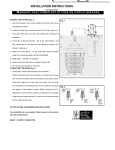
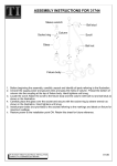
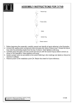
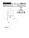
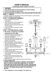
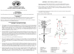
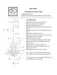
JUNCTION BOX
SUPPLY WIRE
AUBREY CHANDELIER LIGHT
ASSEMBLY/INSTALLATION INSTRUCTIONS
1.
Before beginning the installation, carefully unpack and identify all parts. Make sure the
supply power is OFF.
2. Carefully separate SUPPORT ARMS by gently and evenly spreading them apart.
See Figure 1.
3. Thread NIPPLE A SECURELY onto the COUPLING which is located on top of the
FIXTURE ASSEMBLY. Slide TUBE A, TUBE COVER A, TUBE B, TUBE COVER B,
TUBE C and TUBE COVER C over the wires and secure them with the FIXTURE LOOP
(Carefully pulling excess wire through FIXTURE LOOP).
4. Secure the CROSSBAR to the JUNCTION BOX with (2) JUNCTION BOX SCREWS.
Thread LOCK NUT A and VIBRATION PROOF WASHER A to the top end of NIPPLE B.
Thread NIPPLE B into the center of the CROSSBAR. Locate LOCK NUT B and thread
onto bottom end of NIPPLE B. Tighten LOCK NUT A against CROSSBAR with pliers
until snug.
5. Locate the FIXTURE CHAIN and determine desired hanging height of fixture. Adjust
chain by removing links as needed. Please note that you may want to use chain pliers to
spread links open (See Figure 2). Attach one end of chain to FIXTURE LOOP. Unravel
FIXTURE WIRES and GROUND WIRE and pass wires through FIXTURE CHAIN
alternating links at every 3 inches. Continue to pull the fixture wires through the following
mounting components: CANOPY LOCK RING, CEILING CANOPY, CANOPY CHAIN
LOOP and VIBRATION PROOF WASHER B.
6. MAKE ELECTRICAL CONNECTIONS: (We recommend 2 people for the remainder
of installation) Position the FIXTURE under the JUNCTION BOX and pass the FIXTURE
WIRES and GROUND WIRES through the center of the NIPPLE B. Using WIRE NUTS,
connect the SUPPLY GROUND WIRE to the FIXTURE GROUND WIRE and secure to
the CROSSBAR with GREEN GROUND SCREW. Connect the SUPPLY WHITE WIRE
to the FIXTURE WHITE (or RIBBED) LEAD; Connect the SUPPLY BLACK (or RED)
WIRE to the FIXTURE BLACK (or SMOOTH) LEAD. Wrap all connections with
approved electrical tape.
7. With the connections properly made, carefully tuck all wires into JUNCTION BOX.
Locate the CANOPY CHAIN LOOP and thread onto the end of the NIPPLE B. Thread
LOCK NUT B and VIBRATION PROOF WASHER B on to NIPPLE B and tighten
against CANOPY CHAIN LOOP. Pull the center hole in the CEILING CANOPY over the
CANOPY CHAIN LOOP and secure to ceiling by threading CANOPY LOCK RING onto
CANOPY CHAIN LOOP.
8. Locate the GLASS SHADE and place over the SOCKET. Thread SOCKET RING onto
end of the SOCKET and hand-tighten until snug. Repeat for each GLASS SHADE.
9. Install LIGHT BULB (sold separately) referring to fixture label for bulb type and
maximum wattage.
10. Restore supply power (ON). Retain this sheet for future reference.
IF IN DOUBT ABOUT ELECTRICAL INSTALLATION,
CONSULT A LICENSED ELECTRICIAN.
Customer Service:
1-800-558-8700
FIXTURE WIRE
WIRE NUT
GROUND WIRE
CROSS BAR
GREEN GROUND SCREW
JUNCTION BOX SCREW
LOCK NUT A
VIBRATION PROOF
WASHER A
NIPPLE B
LOCK NUT B
VIBRATION PROOF WASHER B
CANOPY CHAIN LOOP
CEILING CANOPY
LIGHT BULB
(Sold Separately)
Note: This illustration is based on #556647 (3 Lights), the assembly/ installation
instructions for #556639 (5 Lights) is same as #556647 (3 Lights).