1
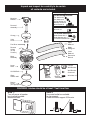
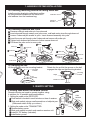
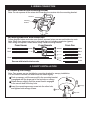
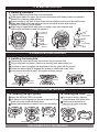
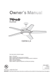
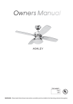
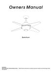
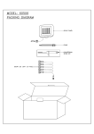
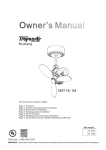
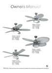
Owner’s Manual
Triton II
Model No:
Cover for non-light option
This instructions contains 5 pages:
Page 1: Foreword
Page 2: Unpack and inspect parts contained, and pre-installation notes
Page 3: Hanging system installation and remote setting
Page 4: Wire connection and Canopy installation
Page 5: Blade and Light/Cover installation
Net Weight
KGS
LBS
Toll Free 1-855-676-7247
WARNING: Read and follow these instructions carefully and be mindful of all warnings shown throughout.
READ AND SAVE THESE INSTRUCTIONS
WARNING : TO REDUCE THE RISK OF FIRE, ELECTRICAL SHOCK, OR INJURY
TO PERSONS, PLEASE OBSERVE THE FOLLOWING:
1.]
To ensure success of installation, be sure read these instructions and review the
diagrams thoroughly before beginning.
2.]
To avoid possible electric shock, be sure electricity is turned off at the main
power box before wiring.
All electrical connections must be made in accordance with local codes, ordinances
and/or the National Electrical Code. If you are unfamiliar with the methods of installing
electrical wiring and products, secure the services of a qualified and licensed
electrician as well as someone who can check the strength of the supportive ceiling
members and make the proper installations and connections.
3.]
Make sure that your installation site will not allow rotating fan blades to come into
contact with any object. Blades should be at least 7 feet from the floor when fan is in
operation.
4.]
If possible, mount ceiling fan on a ceiling joist - the joist must be able to support the
motion and weight of the moving fan. If the fan will be mounted on a ceiling outlet box,
a 4” x 2 - 1/8” deep METAL octagon box is required; one UL listed as “suitable for fan
support”. The box and its supporting members must not be able to twist or work loose.
DO NOT USE PLASTIC BOXES. Installation on a concrete ceiling should be
performed by qualified personnel.
5.]
Blades should be attached after motor housing is hung and in place. Fan motor
housing should be kept in carton until ready to be installed to protect its finish. If you
are installing more than one ceiling fan, make sure that you do not mix fan blade sets.
6.]
After making electrical connections, spliced conductors should be turned upward and
pushed carefully up into the outlet box. The wires should be spread apart with the
grounded conductor and the equipment-grounding conductor on one side of the outlet
box and the “HOT” wires on the other side.
7.]
Electrical diagrams are for reference only. Light kits that are not packed with the fan
must be UL/ETC listed and should be installed per the light kit’s installation
instructions.
8.]
After fan is completely installed, check to make sure that all connections are secure to
prevent fan from falling and/or causing damage or injury.
9.]
The fan can be made to work immediately after installation. The bearings are
adequately charged with grease, so that, under normal conditions, further lubrication
should not be necessary.
10.] The fan must be turned off and stopped before reversing fan direction.
11.] This fan is suitable for sloped ceiling.
12.] This fan is electrically reversible.
13.] This fan includes an optional light kit.
14.] This fan is controlled by remote control.
15.] This fan is suitable for indoor use.
Unpack and inspect fan carefully to be certain
all contents are included.
Hardware Bag
For Mounting Bracket:
Flat Washer x2
Star Washer x2
Spring Washer x2
Machine Screw x2
Wood Screw x2
Mounting
Bracket
Downrod
Assembly
For Wire Connection
Wire Nut x3
For Blade Installation
Canopy
Blade Screw x24 +1
Blade Washer x24 +1
Countersink Screws x6 +1
Yoke
Cover
Upper
Blade x3
Fan Wires
Reverse
Switch
(on top
of motor)
Blade
Wedge x3
Motor
Assembly
Decorative
Nuts x6
Lower
Plate
Remote
Wall Bracket
G9 75W Bulb
Wall Bracket
Screws x2
Lower
Blade x3
Glass
Shade
Remote
Receiver
Remote
Transmitter
Wire Nuts x 5
Bottom
Cover
(non-light option)
WARNING: blades should be at least 7 feet from floor
Note 1:
Turn off power at breaker
box to avoid possible
electrical shock.
Note 2:
Use metal outlet box suitable
for fan support.
Outlet box must support 35 lbs min.
1. HANGING SYSTEM INSTALLATION
1A. Installing mounting bracket to ceiling outlet box
Install mounting bracket to outlet box in ceiling
by using screws included with the outlet box
and washers from the hardware bag.
Outlet Box
Mounting
Bracket
1B. Installing Downrod and Yoke
Remove cross pin and cotter pin from downrod
Insert downrod through canopy and yoke cover, and feed motor wires through downrod.
Loosen 2 downrod jam screws at yoke. Insert downrod assembly into yoke.
Insert the cross pin through yoke & downrod and secure with cotter pin.
Tighten both downrod jam screws to further secure downrod.
Pull down the yoke cover to cover yoke.
Wires
Downrod
Assembly
Downrod
Cross Pin
Cotter Pin
Canopy
Cotter Pin
Downrod Jam
Screw (2)
(Loosen)
Yoke
Downrod Jam
Screw (2)
(Tighten)
Yoke
Cover
Cross Pin
Yoke
Yoke Cover
1C. Hanging the fan
Lift fan assembly onto the mounting bracket.
Mounting
Bracket
Rotate the fan so that the groove on the ball
engages the ridge on the mounting bracket.
Ridge
Mounting
Bracket
Fan
Assembly
Ball Groove
2. REMOTE SETTING
2. Setting code switch for remote control
Remote controls are tuned to operate together using
4 switches for 16 possible code combinations.
1. Setting the code on the RECEIVER:
Code switch is located in small window on face of receiver.
Slide code switch using a small screwdriver or ballpoint pen.
(Slide each switch firmly up or down.)
2. Setting the code on the TRANSMITTER:
Remove battery cover.
Slide code switch to match code used on receiver unit
Install 9V DC battery (included).
Install battery cover
Code
switches
3. WIRING CONNECTION
3A. Insert receiver into mounting bracket
Note: Do not squeeze all the wires while inserting the receiver into the mounting bracket.
Receiver
Mounting
Bracket
3B. Making electrical wire connection
Follow diagram below and make sure that all exposed wires are secured inside wire nuts.
Note: Wires from house may vary in color and may not include ground wire (green).
After wiring is complete, collect wires neatly inside mounting bracket.
From House
White
Black
From Remote
From Fan
(AC-N)
(Motor-N)
(AC-L)
(Motor-L)
White
Black
(For light kit)
Green
(For ground wire)
(From downrod)
Secure with twist-lock wire nuts.
(From mounting bracket)
Blue
Green
Green
4. CANOPY INSTALLATION
4. Installing the canopy
Note: Two screws are pre-installed on mounting bracket for canopy installation.
You will need to remove one and loosen the other slightly.
Push up canopy until the screw still in the mounting bracket
is engaged with the large end of the keyhole on canopy.
Rotate canopy slightly until the screw head is engaged
in the narrow end of the key hole.
Insert the remaining canopy screw into the other hole,
and tighten both canopy screws.
Screw
Canopy
Key Hole
5. BLADE INSTALLATION
5. Installing the blades
Tip: Upper blades are shorter than the lower blades.
Slide upper blade into upper slot of motor and secure with blade screws and washers.
Repeat for remaining upper blades.
Secure wedge to top face of lower blade with countersink screws and decorative caps.
Slide lower blade into lower slot and secure with blade screws and washers.
Repeat for remaining lower blades.
Align holes in upper blade with posts of wedge, snap them together and
secure with two blade screws and washers.
Countersink
Screws (2)
Upper Blade
Wedge
Lower
Blade
Lower Blade
Decorative
Nuts (2)
Upper Blades
Lower Blades
6. LOWER PLATE INSTALLATION
6. Installing the lower plate
Remove one screw and loosen two screws from the central hub.
Plug in electrical connectors. Nest wires carefully into recess while you...
Lift plate to motor to engage the large end of the key holes with the screws.
Rotate the plate slightly to engage two screws in small ends of key holes.
Insert screw removed in step 1 and tighten all three screws.
Plug in
Connectors
Recess
Loosen
two screws
Remove
one screw
Insert
Screw
Align
key holes
with screws
7. LIGHT/COVER INSTALLATION
7B. Installing the Cover Non-light
option
7A. Installing the light (option)
Insert the G9 Bulb (75W) into socket.
Lift glass to motor aligning the groves in the neck of the
glass to the nibs inside the lower plate.
Rotate glass clockwise to secure it to motor assembly.
Nib
Lift cover to motor, aligning
threaded post with center hole.
Rotate cover clockwise to
secure it to motor assembly.
Glass
Shade
Insert
G9 Bulb
Groove
TURN POWER ON AT THE BREAKER
Cover
Plate