1
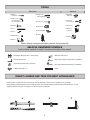
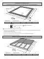
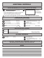
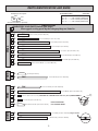
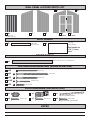
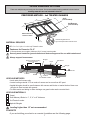
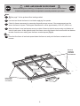
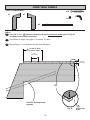
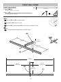
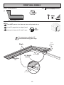
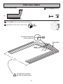
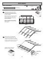
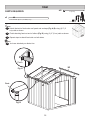
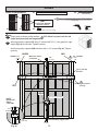
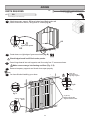
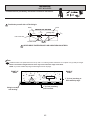
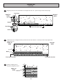
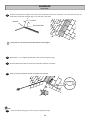
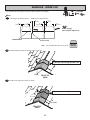
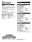
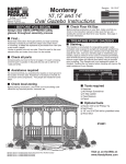
16772-N STOP! Call Us First! DO NOT RETURN TO STORE. For immediate help with assembly or product information call our toll free number: 1-888-827-9056 or email: [email protected] Our staff is ready to provide assistance April through October M-F 8:00 AM to 4:30 PM EST Saturday 8:30 AM to 4:30 PM EST November through March M - F 8:00 AM to 5:00 PM EST (This page intentionally left blank.) ASSEMBLY MANUAL 16772-N 1/21/2013 GABLE 8' x 8' (244 x 244 cm) ACTUAL FLOOR SIZE IS 96 x 92 -5/8" (244 x 235 cm) KEEP THIS MANUAL FOR FUTURE REFERENCE IMPORTANT! READ INSTRUCTIONS THOROUGHLY PRIOR TO BEGINNING ASSEMBLY. BEFORE YOU BEGIN •BUILDING RESTRICTIONS AND APPROVALS Be sure to check with local building department and homeowners association for specific restrictions and/ or requirements before building. •ENGINEERED DRAWINGS Contact our Customer Service Team if engineered drawings are needed to pull local permits. •SURFACE PREPARATION To ensure proper assembly you must build your shed on a level surface. Recommended methods and materials to level your shed are listed on pages 7. •CHECK ALL PARTS Inventory all parts listed on pages 5 - 6. Contact our Customer Service Team if any parts are missing or damaged. •ADDITIONAL MATERIALS You will need additional materials to complete your shed. See page 4 for required and optional materials and quantities. - CUSTOMER SERVICE Call: 1-888-827-9056 email: [email protected] TOOLS Required Phillips Screwdriver Optional Tool Belt/ Nail Pouch Utility Knife Shingle Blades Drill / Driver 3/8" Drill Bit #2 Philips Drive Bit Tin Snips (for drip edge) Caulk Gun Hammer Chalk Line Paint Tools Level Nail Gun Pencil Safety Glasses Tape Measure Ladder Square • gun nails Gloves or Safety! Always use approved safety glasses during assembly. HELPFUL REMINDER SYMBOLS Look for these symbols for helpful reminders throughout this manual. = Assistance Required; two or more people. = Mark part with pencil. = Ensure squareness. BEGIN = Important required step or operation. FINISH = You have finished the assembly or installation. = Helpful assembly hint. = Beginning of steps for assembly or installation. = Level ORIENT LUMBER AND TRIM FOR BEST APPEARANCE Framing lumber is graded for structural strength and not appearance. Exterior trim is graded for one good side. Always install the material leaving the best edge and best surface visible. Please remember that these blemishes in no way negatively affect the strength or integrity of our product. (See Fig. A, B, C.) A B 2 C CONCRETE FOUNDATION If you choose to install your kit on a concrete slab refer to the diagram below. Treated Sill Plate Caulk between sill plate and concrete. 3-1/2" (8,9 cm) B C A DOOR Building Size 4" (10 cm) Actual Floor Size 8'x 8' (244 x 244 cm) 8'x 7'-8-5/8" (244 x 235,3 cm) A B C 96" (244 cm) 85-5/8" (217,5 cm) 92-5/8" (235,3 cm) Requires: x4 2 x 4 x 8' (5 x 10 x 244 cm) MUST be treated lumber. x1 Caulk Allow new concrete slabs to cure for at least seven (7) days. • A treated 2 x 4" (5 x 10 cm) sill plate is required when installing your shed on concrete. Hint: Use treated lumber in your kit or purchase full length treated lumber. • Use a high quality exterior grade caulk beneath all sill plates. • Fasten 2 x 4" (5 x 10 cm) sill plates to slab using approved concrete anchors (fasteners not included). • Check local code for concrete foundation requirements. WOOD FLOOR FRAME (NOT INCLUDED) B C 24" (61 cm) DOOR Building Size 8'x 8' (244 x 244 cm) A Actual Floor Size 8'x 7'-8-5/8" (244 x 235,3 cm) A B C 96" (244 cm) 89-5/8" (227,6 cm) 92-5/8" (235,3 cm) Required Floor materials on following page. 3 ADDITIONAL MATERIALS FLOOR MATERIALS x7 (24" O.C. WOOD FLOOR OPTION SHOWN) 2 x 4 x 8' (5 x 10 x 244 cm) Treated Lumber 48" x 92-5/8" (122 x 235,3 cm) x2 Cut (5) to 2 x 4 x 89-1/2" (5 x 10 x 227 cm) Floor panels are 5/8" (16 mm) thick. • See the FLOOR LEVELING section on page 7 for recommended methods and suggested materials to properly level your floor, as this will vary depending on your specific site. If you reqiure a stronger floor, you will need to purchase additional 2"x4"x8' material. COMPLETING YOUR SHED You will need these additional materials: 3-TAB SHINGLES ............................ 4 Bundles 1" GALVANIZED ROOFING NAILS.... 2 Lbs For shingles. PAINT FOR SIDING .......................... 2 Gallons PAINT FOR TRIM .............................1 Quart Use 100% acrylic latex exterior paint. (2) coats recommended. Use 100% acrylic latex exterior paint. CAULK ................................................. 2 Tubes WOOD GLUE ....................... Exterior Rated Use acrylic latex exterior caulk that is paintable. NAIL BOXES (Not included) x2 BOXES x3 BOXES 3" (7,6 cm) Shown Actual Size 2" (5,0 cm) OPTIONAL MATERIALS DRIP EDGE ..................... 34 Feet #15 ROOFING FELT To cover 73 Sq. Ft. of roof area. 1" GALVANIZED ROOFING NAILS.........1/4 Lb For roofing felt. REFER TO THE BACK OF THIS MANUAL AND THE MANUFACTURER’S INSTRUCTIONS FOR INSTALLATION OF SHINGLES, DRIP EDGE AND FELT. NOTES 4 PARTS IDENTIFICATION AND SIZES Part identification is stamped on some parts. WOOD SIZE CONVERSION CHART Nominal Board Size Actual Size 2" x 4"..............1-1/2" x 3-1/2" (3,8 x 8,9 cm) 1" x 4".................3/4" x 3-1/2" (1,9 x 8,9 cm) RS RS 2" x 3"..............1-1/2" x 2-1/2" (3,8 x 6,3 cm) 1" x 3".................3/4" x 2-1/2" (3,8 x 6,3 cm) • Check these locations for part stamp. PARTS LIST WALL INVENTORY YOUR PARTS before you begin. We suggest sorting parts by the category they are listed in. x5 BV x2 NJ x6 OV 2 x 3 x 69" (5 x 7,6 x 175,3 cm) x4 OY 2 x 3 x 72" (5 x 7,6 x 183 cm) x1 PS x2 PNA x1 PT 2 x 3 x 17-1/2" (5 x 7,6 x 44,5 cm) 2 x 3 x 43-3/4" (5 x 7,6 x 111,1 cm) 2 x 3 x 91 " (5 x 7,6 x 231,1 cm) 2 x 3 x 96" (5 x 7,6 x 244 cm) TRIM TRUSS x4 7/16" x 2-1/2 x 24-3/4" " (1 x 6,3 x 62,9 cm) x6 6 x 24" (15 x 61 cm) x6 RAZ x4 PAX x2 HS x5 GAA x4 GBA 2 x 4 x 53-1/4" (5 x 10 x 135,3 cm) 2 x 3 x 41-11/16" (5 x 7,6 x 105,9 cm) 1 x 3 x 94-3/4" (2,5 x 7,6 x 240,1 cm) 1 x 3 x 5" (2,5 x 7,6 x 12,7 cm) ONE USED AS A GAUGE BLOCK FOR 3/4" (19 mm) MEASUREMENT x4 DOOR 2 x 3 x 92-1/2" (5 x 7,6 x 235 cm) 1 x 3 x 8-1/4" (2,5 x 7,6 x 21 cm) 3/4 x 6-1/4 x 11-7/8" (1,9 x 15,8 x 30 cm) x2 OO x1 ZB RIGHT PAINTED RED LEFT PAINTED GREEN 2 x 3 x 69" (5 x 7,6 x 175,3 cm) Finger Jointed 5/8 x 3 x 55" (1,6 x 7,6 x 140 cm) 5 3/4" (19 mm) WALL PANEL & DOORS PARTS LIST x1 x4 x1 x1 3/8 x 48 x 72" (1 x 122 x 183 cm) x1 x1 x1 LEFT DOOR RIGHT DOOR ROOF PANELS x2 48" x 96" (122 x 244 cm) x2 6-3/8" x 96" (16,2 x 244 cm) Roof panels are 7/16" (11 mm) thick. SOFFIT PANELS 3/8 x 5 x 93-1/4" (0,9 x 12,7 x 236,9 cm) x2 FASTENER/HARDWARE BAG (Shown Actual Size) x28 2" (5,0 cm) x50 3" (7,6 cm) x22 2" (5,0 cm) x106 x58 1-1/4" (3,2 cm) 3/4" (19 mm) DOOR HARDWARE (Not Actual Size) x1 x1 x1 48" (122 cm) Metal Threshold x4 3/4" (19 mm) x7 3/4" (19 mm) x8 3/4" (19 mm) Bagged seperately / special coating NOTES 6 FLOOR LEVELING OPTIONS There are multiple ways to level your floor frame. Our recommended leveling method is shown below. Leveling materials are not included in this kit. PREFERRED METHOD - 4x4 TREATED RUNNERS 2x4's (not included). 96" (244 cm) 4x4 Runners (not included). 12" (30,5 cm) Measurements to centers of 4x4's. RR DOODOO • 3" Screw angled into 4x4. • (2) at each point frame and 4x4 touch. 12" (30,5 cm) MATERIAL REQUIRED x2 4" x 4" x 8' (10 x 10 x 244 cm) Treated Lumber Fasteners for Frame to 4"x 4". (3" Screws shown as one option.) Minimum (20) 3" screws / exterior grade. Use only wood treated for ground contact and fasteners approved for use with treated wood. Always support frame seams. Maximum between leveling material locations. Shingle 4x4 Runner Level 48" 12" 12" Shingle Do not exceed 16". Gravel 2" Block Gravel LEVELING METHODS 4" Block 2x4 Treated Lumber 8" Block • Level under 4x4 runners only. • Locate leveling material 12" from ends of runners and no more than 48" apart. • Asphalt shingles should be used between 4x4 runners and blocks or treated lumber. Never use shingles in direct contact with ground. • For best results and aiding in water drainage use gravel under each concrete block. LEVELING MATERIALS Gravel Solid Masonry Blocks in 1", 2", 4" or 8" thickness 2x4 Treated Lumber Asphalt Shingles Leveling higher than 16" not recommended. CONCRETE • If you are building your shed on a concrete foundation see the following page. 7 LEVEL AND SQUARE FLOOR FRAME Before attaching floor decking, it is important to level and square the floor frame. A level and square floor frame is required to correctly construct your shed. BEGIN 1 See page 7 for the preferred floor leveling method. 2 Use level and check the frame is level before applying floor panels. 3 Check for frame squareness by measuring diagonally across corners. If the measurements are the same, the frame is square. The diagonal measurement will be approximately 133-5/16" (338,6 cm). 4 When the frame is level and square secure one side of frame to the 4x4 runners using one fastener at ends of each runner. At the opposite end of the frame, secure the frame to 4x4 runners with one fastener at ends of each runner making sure the frame remains square (Fig. A). FINISH 5 Once the floor frame is level and square fasten the frame at each point the frame contacts the 4x4 runners. Second, secure at ends with one fastener. 133-5/16" (338,6 cm) 133-5/16" (338,6 cm) Fig. A OOR D R DOO First, secure at ends with one fastener. 8 IMPORTANT! IMP O R TA N T ! Check the floor frame is level after installing floor panels. Re-level if needed. OR DO • The floor should be used as a stable work surface for wall construction. HINT: • Organize your assembly procedure during the build process to avoid over-handling of the walls. BACKWALL SIDEWALL OR DO SIDEWALL FRONTWALL 9 RAFTER ASSEMBLY JIG x8 PARTS REQUIRED: x2 GAA 3/4 x 3 x 5" (1,9 x 7,6 x 12,7 cm) x2 GBA 3/4 x 3 x 8-1/4" (1,9 x 7,6 x 21 cm) ¸1 1-1/4" (3,2 cm) BEGIN Build a Jig to ensure all Rafters are assembled the same. Mark a straight line on the Floor from corner to corner. 3 Screw blocks in place to measurement shown. D O O R 2 Make sure blocks are square and at 101" (256,5 cm) FINISH 4 You have finished building a Rafter Jig. (2) 1-1/4" (3,2 cm) Screws per block 101" (256,5 cm) Square Chalk Line 101" (256,5 cm) GAA GAA GBA GBA Flush Flush 10 RAFTERS PARTS REQUIRED: x72 2" (5 cm) 6 x 24" (15 x 61 cm) x6 x6 RAZ 2 x 4 x 53-1/4" (5 x 10 x 135,3 cm) ¸1 BEGIN Place two rafter halves RAZ on floor jig. You will assemble (3) rafters. 2 Flip over rafter assembly and glue and nail gusset to back side. 5 Repeat steps 1-4 to build two more assemblies. O 4 O Nail gusset onto rafter using 2" nails, staggered, as shown. D 3 R Apply glue on gusset and place on rafters. FINISH 6 Unscrew jig and save blocks. Set aside rafters and proceed to building your back wall. Contact at peak. 1/4" (0,6 cm) Gap Glue Gusset 101" (256,5 cm) Use Jig to assemble Rafters. 11 BACK WALL PANELS PARTS REQUIRED: x16 1-1/4" (3 cm) x1 x1 OY x2 2 x 3 x 72" (5 x 7,6 x 183 cm) BEGIN 1 3 Repeat Steps 1 - 2 to assemble the right back wall panel D O O R 2 Place OY on floor. Place the left back wall panel primed side down onto OY (Fig. A) and flush to panel edges as shown. Secure flush to edges using eight 1-1/4 screws 10" apart. OY FINISH 4 You have finished building your back wall panels. Primed Side Down. Locate OY flush to these edges. Fig A. 10" (25,4 cm) 2-1/2" (6,4 cm) Use 2x3 for temporary support 12 BACK WALL FRAME PARTS REQUIRED: x1 x2 3" (7,6 cm) NJ 2 x 3 x 43-3/4" (5 x 7,6 x 111 cm) x1 PT 2 x 3 x 96" (5 x 7,6 x 244 cm) BEGIN Orient parts on edge on floor as shown. 2 Nail using two 3" nails at each connection. D O O R 1 3" (7,6 cm) Nails 96" (244 cm) 48" (122 cm) 48" (122 cm) PT 1-1/2" (3,8 cm) NJ 43-3/4" (111 cm) 1-1/2" (3,8 cm) 13 HINT: BACK WALL FRAME x2 PARTS REQUIRED: x1 3" (7,6 cm) NJ 2 x 3 x 43- 3/4" (5 x 7,6 x 111,1 cm) 3 Orient parts on edge on floor as shown. 4 Use two 3" screws at middle connection. FINISH O O R You have finished building your back wall frame. D 5 48" (122 cm) 48" (122 cm) 1-1/2 (3,8 cm) NJ 43-3/4" (111cm) (2) 3" (7,6 cm) Screws 14 BACK WALL PANELS PARTS REQUIRED: x16 x1 x1 2" (5 cm) 3" (7,6 cm) GAA 3/4" GAUGE BLOCK Pre-Assembled LEFT BEGIN Place LEFT panel on back frame as shown with primed side facing up. 2 Use a 3/4" gauge block at edge of panel. 3 Nail using 2" nails 6" apart on edges and 12" apart inside panel. 4 Use (1) 3" screw at end D . O O R 1 Do not nail in groove. (1) 3" Screw Flush For squareness maintain 3/4" measurement along panel edges. 3/4" (1,9 cm) Primed side UP 12" (30,5 cm) 6" (15,2 cm) 6" (15,2 cm) Square Gauge Block 3/4" (1,9 cm) 1" (2,5 cm) 15 BACK WALL PANELS PARTS REQUIRED: x16 2" (5 cm) x1 x1 3" (7,6 cm) Pre-Assembled RIGHT 5 Place RIGHT panel on back frame as shown with primed side facing up. 6 Nail using 2" nails 6" apart on edges and 12" apart inside panel. 7 Use (1) 3" screw at end. . D O O R Do not nail in groove. Flush To draw panels tight at seams angle nail. 6" (15,2 cm) (1) 3" screw 12" (30,5 cm) 96" (244 cm) Flush Flush (1) 3" screw 16 BACK WALL BOTTOM PLATES PARTS REQUIRED: x2 x6 2" (5 cm) BV 2 x 3 x 17-1/2" (5 x 7,6 x 44,5 cm) BEGIN Position BV on edge, flush with outside edge and 1" from bottom edge of LEFT wall panel. (Fig A.) 2 Nail BV to wall panel using (3) 2" Nails. 3 Repeat step 1-2 for RIGHT wall panel. (Fig B.) D O O R 1 FINISH 4 You have finished building your back wall. 1" (2,5 cm) 2-1/2" (6,3 cm) Flush Fig A. 2-1/2" (6,3 cm) 1" (2,5 cm) Fig B. 17 FRONT WALL PANELS PARTS REQUIRED: x1 x16 1-1/4" (3 cm) x1 OY x2 2 x 3 x 72" (5 x 7,6 x 183 cm) BEGIN 1 Place OY on floor. Place the left front wall panel primed side down onto OY (Fig. A) and flush to panel edges as shown. 2 Secure flush to edges using eight 1-1/4 screws 10" apart. 3 Repeat Steps 1 - 2 to assemble the right front wall panel. Locate OY flush to these edges. 10" (25,4 cm) 2-1/2" (6,3 cm) OY Use 2x3 for temporary support Fig A. 18 Primed Side Down. FRONT WALL FRAME PARTS REQUIRED: x2 3" (7,6 cm) BV x1 2 x 3 x 17-1/2" (5 x 7,6 x 44,5 cm) x2 PS 2 x 3 x 91" (5 x 7,6 x 231 cm) Nail PS to BV with two 3" nails. 3 Ensure BV is centered with PS and nail in place with two 3" nails. O 2 O Lay out PS, and BV on edge on floor. D 1 R BEGIN FINISH 4 You have finished building your Front Wall Frame. BV 45-1/2" (115,6 cm) HINT: 2-1/2" (6,4 cm) 2-1/2" (6,4 cm) 45-1/2" (115,6 cm) PS 91" (231 cm) 45-1/2" (115,6 cm) 45-1/2" (115,6 cm) BV 17-1/2" (44,5 cm) 19 PS FRONT WALL PANELS x22 PARTS REQUIRED: 2" (5 cm) GAA x1 3/4" GAUGE BLOCK Pre-Assembled LEFT BEGIN 1 Place LEFT panel on front frame as shown with primed side up. 2 Use a 3/4" gauge block on edge of panel. 3 Nail panel to frame with 2" nails 6" apart. D O O R Do not nail in groove. For squareness, maintain 3/4" measurements along panel edge. 3/4" (1,9 cm) Flush 6" (15,2 cm) 3/4" GAUGE BLOCK Primed Side UP 3/4" (1.9 cm) 20 FRONT WALL PANELS x10 PARTS REQUIRED: 2" (5 cm) x1 Pre-Assembled RIGHT 4 Place RIGHT panel on front frame primed side up. 5 Nail panel to frame with 2" nails 6" apart. D O O R Do not nail in groove. To draw panels tight at seams, angle nail. Primed Side UP Panels Flush 6" (15,2 cm) 96" (244 cm) For squareness, maintain 96" (244 cm) measurement. 21 FRONT WALL BOTTOM PLATES PARTS REQUIRED: x2 x6 2" (5 cm) BV 2 x 3 x 17-1/2" (5 x 7,6 x 44,5 cm) BEGIN BEGIN Position BV on edge, flush with outside edge and 1" from bottom edge of LEFT wall panel. (Fig A.) 2 Nail BV to wall panel using (3) 2" Nails. 3 Repeat step 1-2 for RIGHT wall panel. (Fig B.) D O O R 1 FINISH 4 You have finished building your front wall. 1" (2,5 cm) 2-1/2" (6,3 cm) Flush Fig A. 2-1/2" (6,3 cm) Fig B. 1" (2,5 cm) 22 SIDE WALL FRAMES x6 PARTS REQUIRED: 3" (7,6 cm) x4 7/16 x 2-1/2 x 24-3/4" (1,1 x 6,4 x 62,9 cm) x6 x8 2" (5 cm) OV 2 x 3 x 69" (5 x 7,6 x 175 cm) x2 PNA 2 x 3 x 92-1/2" (5 x 7,6 x 235cm) BEGIN 1 Orient parts on edge on floor. Measure and mark from end of boards. IMPORTANT! You will build two walls the same. 2 Use two 3" nails at each mark. 3" (7,6 cm) Nails 46-1/4" (117,5 cm) 22-1/4" (57 cm) 22-1/4" (57 cm) 1-1/2" (3,8 cm) PNA Center on marks. OV x3 1-1/2" (3,8 cm) HINT: 2" (5 cm) Nails 24-3/4" (63 cm) 24-3/4" (63 cm) 49-1/2" (125,7 cm) 23 SIDE WALL FRAME- SOFFIT PARTS REQUIRED: x22 1-1/4" (3,2 cm) x2 3/8 x 5 x 93-1/4" (0,9 x 12,7 x 236,9 cm) 3 Place panel onto 2 x 3 with primed side against 2 x 3 (Fig A) Keep panel flush along entire edge of 2 x 3 top plate (Fig A). O R Attach soffit panel flush to 2 x 3 (Fig A) and with 3/8" offset at ends (Fig. B, C) using fourteen 1-1/4" screws. D O 4 9-1/2" (24 cm) 3/8" (10 mm) 3/8" (10 mm) Fig. B 93-1/4" (236,9 cm) Fig. C PRIMED SIDE Flush Fig. A 24 SIDE WALL PANELS PARTS REQUIRED: x58 2" (5 cm) GAA 3/4" GAUGE BLOCK x2 3/8 x 48 x 72" (1 x 122 x 183 cm) 5 Ensure your wall frame is square by installing one panel and squaring frame. Place the 48 x 72" panel onto wall frame with primed side up as shown. NOTE THE LIP AND SQUARE EDGES. D O O R Use the gauge block to mark the 3/4" measurement on the wall stud. Locate the panel flush under the soffit panel. Secure panel with two 2" nails in the corners (Fig. A). 6 Move to the opposite end. Using the long edge of the panel as a lever move the panel side-to-side until you have a 3/4" measurement on the wall stud. Secure corner with two 2" nails (Fig. B). 7 Nail the panel using 2" nails 6" apart on edges and 12" apart inside panel. Do not nail in groove. For squareness maintain 3/4" and flush under soffit panel. Flush BEGIN HERE 2 Nails There will be an overhang at top. Flush 3/4" (19 mm) 3/4" (19 mm) Primed Side UP 3/4" Gauge Block Fig. A 6" (15 cm) 3/4" (19 mm) 12" (30 cm) Fig. B 2 Nails LIP EDGE 3/4" (19 mm) SQUARE EDGE 48" (122 cm) 25 SIDE WALL PANELS PARTS REQUIRED: 2" (5 cm) 3/8" x 48" x 72" (1 x 122 x 183 cm) x2 8 x58 Place 48" panel on frame as shown with primed side facing up. NOTE THE SQUARE AND LIP EDGES. Do not nail in groove. D O O R Nail using 2" nails 6" apart on edges and 12" apart inside panel. Flush To draw panels tight at seams angle nail. 12" (30 cm) 6" (15 cm) 48" (122 cm) LIP EDGE SQUARE EDGE Carefully flip your sidewall over. Repeat STEPS 1-8 to assemble your second side wall. FINISH 9 You have finished building both of your side walls. 26 BACK WALL INSTALLATION PARTS REQUIRED (TEMPORARY): x1 x4 3" (7,6 cm) HS x6 1 x 3 x 94-3/4" (2,5 x 7,6 x 241,1 cm) 3" (7,6 cm) x24 2" (5 cm) BEGIN Center back wall assembly on the 96" (244 cm) floor dimension. 2 Use HS as a temporary brace. Secure with two 3" screws. D O O R 1 3 4 ) 44 cm 96" (2 3" (7,6 cm) Screws First, nail lower edge of panel to floor frame using 2" nails 6" apart. Angle nail to hit floor frame (Fig. A). Do not nail in groove. Screw back wall upright to floor using (2) 3" screws (Fig. B). Continue to nail (3) 3" nails through each bottom plate into floor. FINISH 5 You have finished standing your back wall. 3" (7,6 cm) Screw Nail 2" nails first. Angle to nail into floor frame. Fig. B 2" (5 cm) Nail 6" (15,2 cm) 3" (7,6 cm) Nail 2" (5 cm) Fig. A 3" (7,6 cm) Screw 27 SIDE WALLS INSTALLATION x12 x4 3" (7,6 cm) x62 3" (7,6 cm) 2" (5 cm) BEGIN D O O R Stand right sidewall on floor. It is important to secure the sidewall in the following order. 1 Soffit Panel Center sidewall on floor front to back. Panel Rest the top of the sidewall so the soffit panel overlaps the backwall panel 3/8" (Fig. A). Trim 3/8" (0,9 cm) OVERLAP Fig. A Fig. B Nail the lower sidewall corner to the backwall trim with one 2" nail (Fig. B). DOOR Trim 2" (5 cm) Nail CENTER Fig. C 2 Be sure the measurement between the panel edge and the trim is the same along the entire length. Then secure with one 2" nail in the upper corner (Fig. C). 2" (5 cm) Nail Trim Same Measurement Panel Nail along the panel edge into the trim using 2" nails spaced 6" apart. 6" (15 cm) Nail along bottom of panel using 2" nails 6" apart. Angle nail to hit floor frame (Fig. D). 6" (15 cm) 3 Nail down the bottom plate using two 3" nails between the wall studs. Fig. D 2x3" Screw through the backwall trim into the top plate using one 3" screw (Fig. E). 3" (7,6 cm) Screw Screw through the backwall trim using one 3" screw. Angle screw to hit floor frame (Fig. F). 3" (7,6 cm) Screw Repeat process to secure the left sidewall. 3" (7,6 cm) Screw R 3" (7,6 cm) Nail O O Fig. F D 4 Fig. E 28 FRONT WALL INSTALLATION x34 x4 2" (5 cm) 3" (7,6 cm) x6 3" (7,6 cm) BEGIN Stand frontwall on floor. It is important to secure the frontwall in the following order. Soffit Panel 3/8" (0,9 cm) OVERLAP O O R Center frontwall on floor side-to-side. D 1 Trim Panel The sidewall soffit will overlap the frontwall 3/8" (Fig. A). Fig. A Nail the frontwall flush to the floor using 2" nails 6" apart. Angle nails to hit floor frame (Fig. B). Nail the lower sidewall corner to the frontwall trim with one 2" nail (Fig. C). 2" (5 cm) Nail Fig. B Trim 2" (5 cm) Nail 6" (15 cm) 6" (15 cm) CENTER Fig. C Fig. D 2" (5 cm) Nail 2 Be sure the measurement between the panel edge and the trim is the same along the entire length. Then secure with one 2" nail in the upper corner (Fig. D). Trim Side Panel 6" (15 cm) Nail along the panel edge into the trim using 2" nails spaced 6" apart. Same Measurement 2" (5 cm) Nail 6" (15 cm) 3 2 x 3" Secure the frontwall into the top plate using one 3" screw (Fig. E). Secure the frontwall through the trim using one 3" screw. Angle screw to hit floor frame (Fig. F). 4 Fig. E Continue to nail (3) 3" nails though bottom plate into floor. 3" (7,6 cm) Nails Repeat process to secure the right side of the frontwall. 3" (7,6 cm) Screw FINISH 5 3" (7,6 cm) Screw You have finished installing your front wall. 3" (7,6 cm) Screw 29 Fig. F GABLE TRIM x20 PARTS REQUIRED: x4 1-1/4" (3 cm) PAX 2 x 3 x 41-11/16" (5 x 7,6 x 105,9 cm) ¸1 BEGIN Position one PAX flush to front panel edge and center on right edge of groove (Fig. A). Attach trim with eight 1-1/4" screws from inside. Position second PAX flush to panel edge and flush to PAX already attached (Fig. A). Attach trim with eight 1-1/4" screws from inside. 3 Repeat steps 1-2 to attach the back trim. D O O R 2 FINISH 4 You have attached your upper trim. Flush Fig. A PAX Center on right edge of groove. PAX Flush to top of panel. ) cm ly 3 , e t (20 a 8" roxim p Ap 30 TRIM / ENDCAPS x32 PARTS REQUIRED: x4 1-1/4" (3,2 cm) GAA 3/4 x 3 x 5" (1,9 x 7,6 x 12,7 cm) x4 GBA 3/4 x 3 x 8-1/4" (1,9 x 7,6 x 21 cm) x4 RIGHT PAINTED RED 3/4 x 6-1/4 x 11-7/8" (1,9 x 15,8 x 30 cm) LEFT PAINTED GREEN ¸1 BEGIN Locate endcaps flush with upper trim and corner trim and attach each endcap from inside of shed using four 1-1/4" screws as shown (Fig. A). O 3 O Repeat steps to build two more endcaps. D 2 R Glue 5" and 8-1/4" boards onto endcaps, and fasten with 1-1/4" screws, as shown. FINISH 4 You have finished attaching your endcaps. GAA 5" Board Glue Flush GAA Glue Flush 5" Board Flush 8-1/2" Board Left GREEN GBA GBA Flush Right RED x2 8-1/2" Board x2 (4) 1-1/4" (3,2 cm) Screws Flush Flush Fig. A 31 RAFTERS x12 PARTS REQUIRED: 3" (7,6 cm) pre-assembled x6 2" (5 cm) x3 ¸1 BEGIN 3 Repeat steps to attach three rafters. D O O R 2 Locate rafters directly over studs and flush to overhang in wall frame (Fig. A). Check that you have the measurements shown. Screw through soffit panel into rafters using one 2" screw (Fig. A). Attach with two 3" screws at each end (Fig. B). Re-tighten 2" screws if neccessary. FINISH 4 You have finished attaching your rafters. Fig. B Screw into top plate. Fig.A 2" (5 cm) Screw 1" (2,5 cm) Flush NOTE: Measurements from inside of panels 22-1/4" (56,5 cm) 24" (61 cm) 24" (61 cm) Align over studs. Maintain the measurements between rafters. 32 22-1/4" (56,5 cm) ROOF PANELS PARTS REQUIRED: x4 2" (5 cm) 7/16 x 48 x 96" (1,1 x 122 x 244 cm) x2 Roof panels may cause serious injury until securely fastened. D O O R You must square the roof by attaching one panel first. You will use the panels’ long edge as a lever to bring your roof into square. Commonly known as “racking”. BEGIN 1 Attach the 48 x 96" panel with the rough side up (painted-grid lines side) with a 1/8" measurement on the gable trim (Fig A) and the panel flush at the peak (Fig. B). Flush at peak. Two Nails Secure panel with two 2" nails in the corners. Fig. B (12 48" 2c m) 1/8" (3 mm) Fig. A Flush at peak. 2 Move to the opposite end. Using the long edge of the panel as a lever move the panel side-to-side until the top corner is flush to the peak (Fig. C) and there is 1/8" measurement to the gable trim (Fig. D). Fig. C You may need to move your backwall to get the 1/8" measurement. Secure panel with two 2" nails in the corners. Gable Trim 1/8" (3 mm) Fig. D 33 ROOF PANELS PARTS REQUIRED: x90 7/16 x 6-3/8 x 96" (1,1 x 16,2 x 244 cm) x2 3 2" (5 cm) Keep spacing between the center of the rafters at the lower edge of the panel and secure with one 2" nail into each rafter (Fig. E). R NOTE: Measurements from inside of panels D O O Move to the top of the panel and keep spacing between the center of the rafters. Secure with one 2" nail into each rafter (Fig. E). 22-1/4" (56,5 cm) 24" (61 cm) 24" (61 cm) 22-1/4" (56,5 cm) Nail the roof panel using 2" nails 6" apart on edges and 12" apart inside panel (Fig. F). 2" Nail Fig. E 12" (30,5 cm) Attach the lower roof panels flush to the upper panels and with a 1/8" measurement at the gable trim (Fig.G). Fig. F Nail the roof panel using 2" nails 6" apart on edges and 12" apart inside panel. 6-3/8" (16,2 cm) Repeat process to attach roof panels on the opposite side. 96" (244 cm) Gable Trim Flush O O R 1/8" (3 mm) D 4 6" (15 cm) 34 Fig. G TRIM x20 PARTS REQUIRED: x2 2" (5 cm) HS 1 x 3 x 94-3/4" (2,5 x 7,6 x 240,6 cm) ¸1 BEGIN Attach fascia trim flush under roof panel and endcaps (Fig. A,B) using (2) 2" (5 cm) nails as shown. Finish attaching fascia at end of rafters (Fig. B ) using (2) 2" (5 cm) nails as shown. 3 Repeat steps to attach fascia trim on both sides. D O O R 2 FINISH 4 You have attached your fascia trim. Flush HS Fig. A Flush HS Fig. B 35 DOORS PARTS REQUIRED: x2 OO x1 1-1/4" (3 cm) 2 x 3 x 69" (5 x 7,6 x 175,3 cm) x4 3" (7,6 cm) HINT: Look for 3/8" SPACER attached to doors. x1 x1 Left Door x1 Right Door GAA 1 x 3 x 5" (2,5 x 7,6 x 12,7 cm) BEGIN Orient parts as shown on flat surface. 3/8" offset is to top. Look for red (right) and green (left) on hinge board. 2 Attach temporary support OO using 3" screws with 3/4" (1,9 cm) gap from right edges (Fig. A) and at ends. Tighten securely. D O O R 1 Attach temporary support GAA at bottom with 1-1/4" screws (Fig. A). Tighten securely. GREEN OFFSET 3/8" RED Make sure spacer is attached. (1 cm) 3/8" OFFSET (1 cm) 3/8" (1 cm) (4) 3" (7,6 cm) Screws Tighten screws securely. OO GAA (2) 1-1/4" (3 cm) screws NOTE: Screw hole will be used later. 3/4" (1,9 cm) 3/4" (1,9 cm) (Fig. A) Bottom edges flush. 3/8" (1 cm) 36 DOORS x7 PARTS REQUIRED: x1 3" (7,6 cm) OO 2 x 3 x 69" (5 x 7,6 x 175,3 cm) Attach temporary support OO as a ledger board flush under wall panels for doors to rest on, using three 3" screws (Fig. A). D O O R 3 OO Fig. A Flush against wall panels. OO 4 Center doors on right edge of groove as shown (Fig. B). Check ledger board is still flush under panels. 5 Screw hinge boards into wall supports and floor using four 3" screws as shown. Make sure screws go into framing and floor (Fig. C, D). 6 Remove temporary supports and check doors open properly. FINISH 7 Center 3/8" measurement on right edge of groove. You have finished installing your doors. Fig. B 3/8" (1 cm) Fig. C 3" (7,6 cm) Screws into the wall support and floor frame. Angle 3" (7,6 cm) Screw Fig. D 37 DOOR PARTS REQUIRED: x1 x8 x58 2" (5 cm) ZB 3/4" (19 mm) x8 5/8 x 3 x 55" (1,6 x 7,6 x 140 cm) 3/4" (19 mm) Bagged separately/ special coating x1 48" (122 cm) Metal Threshold Reinforce the door trim using 3/4" screws through door panel into trim (Fig. A). Locate screws as shown in Fig. B. Use two screws at seams. 3 Center trim ZB over doors and secure using eight 2" finish nails into framing as shown. 4 Center metal threshold between doors and secure using (8) 3/4" special coating screws into floor as shown (Fig, C). O 2 O Secure hinge boards from inside using 3/4" screws as shown (Fig. A). D 1 R BEGIN FINISH 5 You have finished securing your door and trim. Door Panel 2" Nails x8 Nail into framing. Center Hinge Board ZB Fig. A Door Trim Install 3/4" screws from inside. x6 CENTER CENTER 14" (35,5 cm) Approximately CENTER CENTER Two Screws (8) Special coating screws Fig. B Fig. C 38 DOOR WEATHERSTRIP x14 PARTS REQUIRED: x2 2" (5 cm) OO 2 x 3 x 69" (5 x 7,6 x 175 cm) With left door closed, center a weatherstrip OO vertically on the left door in the door opening (Fig. A). OO will offset the left door 1" OUT past the door trim 1" (Fig. B). 2 Secure OO using seven 3" screws through outside trim into OO (Fig. B) 3 On right door center OO vertically in door opening (Fig. A). OO will offset the right door 1" IN from the door trim (Fig. C). 4 Secure OO using seven 3" screws through outside trim into OO (Fig. C). D O O 1 R BEGIN FINISH 5 You have finished installing your door weatherstrips. 1" OFFSET (2,5 cm) OO Center OO in door opening. 1" (2,5 cm) Fig. A OFFSET 2" (5 cm) Screw Fig. B Screws 2" (5 cm) x14 11" (28 cm) Approximately 39 DOOR HARDWARE PARTS REQUIRED: x1 x4 x1 3/8" (9 mm) Drill Bit x7 3/4" (1,9 cm) 3/4" (1,9 cm) BEGIN Mount barrel bolt flush at top of OO on left door using 3/4" screws as shown (Fig A). 2 With door closed mark hole location for bolt to extend into. HINT: Extend bolt to leave a mark in wood. Tap bolt with hammer. Drill 3/8" hole deep enough for bolt to slide into. 3 Install hasp on right door and latch on left door. Bottom edge of hasp is 35-1/2" (90 cm) up from bottom edge of door trim. Measure and mark locations and install with 3/4" screws as shown (Fig B). D O O R 1 FINISH 4 You have finished mounting your door hardware. Fig. A Drill 3/8" hole in-line with bolt. Flush on OO. OO HINT: With door closed extend bolt and tap with hammer to leave a mark in wood for drilling. 3/4" (1,9 cm) Screw x7 35-1/2" (90 cm) Fig. B 40 PAINT & CAULK - NOT INCLUDED - • Use acrylic latex caulk that is paintable. Caulk at all horizontal and vertical seams, between the trim and walls, and all around the door trim. • Use a high quality exterior acrylic latex paint. When painting your building, there are a few key areas that can be easily overlooked that must be painted: • Bottom edge of all siding and trim • Inside of doors and all 4 edges Note: Prime all un-primed exterior wood before painting. (Follow directions provided by manufacturer.) ROOF FELT - NOT INCLUDED • Install felt flush to all roof edges overlapping 3". Use minimal amount of roofing nails to hold in place. OK to overlap at ridge. 3" OVERLAP Flush Flush DRIP EDGE - NOT INCLUDED - • Install over roof felt on gable side and under roof felt on eave side (Fig. A). • Do not use nails on side of drip edge that hangs over side of building. • Only nail top of drip edge as shown. Roof Felt Drip Edge Drip Edge Fig. A Edge flush to trim. Snip bottom side of drip edge and bend over to other side of roof. (Follow directions provided by manufacturer.) 41 SHINGLES - NOT INCLUDED • Follow directions provided by manufacturer and these instructions. Familiarize yourself with a 3-Tab Shingle. Notch SHINGLE NAIL PATTERN 1" (2,5 cm) 1/2" (1,3 cm) Notch Sealing Strip 1" (2,5 cm) Half A Rain Slot Full Rain Slot NAILS NEVER DRIVE FASTENERS INTO OR ABOVE SEALING STRIPS. BEGIN 1 Install first starter row upside down and color up with a 1" overhang at back and bottom of roof panel. Use (4) nails per shingle. Starter row must be straight and level all the way across with lower edge of roof deck. NOTE: If you have installed drip edge install shingles flush to drip edge. FRONT OF SHED BACK OF SHED (4) Nails TABS UP 1" (2,5 cm) overhang or flush with drip edge. Shingle overlaps roof decking. 1" (2,5 cm) overhang past roof deck. 42 SHINGLES continued... 2 2 Beginning at front of shed, install first row of shingles with notch at 1" past roof edge or flush with drip edge. Roof Deck FRONT OF SHED 1" (2,5 cm) BACK OF SHED Flush with starter row. Notch - or Drip Edge Flush with starter row. Notch 3 Install second row of shingles flush at top of first row's rain slots. Ensure 1" overhang or flush to drip edge at front, stagger each row. FRONT OF SHED BACK OF SHED 1" (2,5 cm) Notch Flush with rain slots. 4 Continue installing rows of shingles by staggering at front. Flush with rain slots. 1" (2,5 cm) FRONT OF SHED Notch 43 SHINGLES continued... 5 Continue installing rows of shingles to the peak. At the peak make sure there is a maximum of 5" or less to the rain slot, as shown below. If shingles overlap at ridge cut to peak with a utility knife. Cut Off. 5" (12,7 cm) MAX. CUT Top of rain slot. • If more than 5" to rain slot you must install another row of shingles. 6 Repeat steps 1 - 5 to shingle the opposite side of your roof. Trim shingles at ridge. 7 Once both sides are shingled you need to trim ends. Strike a chalk line 1" from edge. 8 Using your shingle hooked blade carefully cut shingles along chalk line. FINISH 9 You have finished shingling your roof. Proceed to capping the ridge. 44 SHINGLES - RIDGE CAP • You will finish off the top of the roof with a ridge cap made from shingles. BEGIN 1 Cut shingles into THREE pieces. Hint: Use cut-off pieces first. 2" (5 cm) 2" (5 cm) 2" (5 cm) 2" (5 cm 2" (5 cm) 2" (5 cm) Score shingle, then snap-off angled cut. Weather Seal Top of slot. Note: • You will need about 20 - 22 cut pieces. 2 20 to 22 Pieces Install first ridge cap flush to shingles at front, as shown. (1) Nail per side through weather seal. Flush 3 FRONT OF SHED Install second ridge cap 5" back, as shown. (1) Nail per side through weather seal. 5" 12,7 cm Flush FRONT OF SHED 45 SHINGLES - RIDGE CAP continued... 4 Continue installing ridge cap to back of roof. 5 Make sure there is 4" between the shingle-color and edge of shingles. Trim cap off flush to shingles 6 When you have 4" minimum of shingle color cut one piece to cap your roof. Cap 7 Install flush to shingles. Flush to shingles (2) Nails per side. FINISH 8 You have finished your ridge cap. 46 WARRANTY Backyard Storage Solutions, LLC warrants the following: Limited Conditional 1. Every product is warranted from defects in workmanship and manufacturing for one year. Warranty * 2. All hardware and metal components are warranted for two years. 3. Trim is warranted for 10 years. 4. Waferboard siding and sheathing is warranted for two years. 5. SmartSide™ siding is warranted for 10 years on all Marco series buildings and 15 years on all Premier Series buildings. 6. Timber series buildings’ siding and trim are warranted for 10 years. 7. Solar Shed windows are warranted for 1 year. 8. Cedar lumber is warranted for 15 years. 9. Cedar doors and Cedar Garden Center are warranted for 10 years. 10. Metal roof is warranted for 25 years. Backyard Storage Solutions, LLC will repair, replace or pay for the affected part. In no event shall Backyard Storage Solutions, LLC pay the cost of labor or installation or any other costs related thereto. All warranties are from date of purchase. If a cash refund is paid on an affected part, it will be prorated from the date of purchase. CONDITIONS The warranty is effective only when: 1. The unit has been erected in accordance with the assembly instructions. 2. The unit has been properly shingled and painted or stained and reasonably and regularly maintained thereafter. 3. The failure occurs when the unit is owned by the original purchaser. 4. Backyard Storage Solutions, LLC has received the warranty registration card within thirty (30) days of purchase and notification of the failure in writing within the warranty period specified above. 5. Backyard Storage Solutions, LLC has had reasonable opportunity during the sixty (60) days following receipt of notification to inspect and verify the failure prior to commencement of any repair work. REQUIREMENTS Storage Buildings & Playhouses To validate your warranty, it is necessary to properly maintain your Backyard Storage Solutions, LLC unit; shingle the roof and paint or solid-colored stain the siding using 100% acrylic latex exterior product with a minimum of two (2) coats within thirty (30) days of assembly; caulk above all doors and all horizontal and vertical trim boards; paint and seal all exposed edges, sides and faces of SmartSide™ and waferboard siding to include all exterior walls and all sides and all edges of doors. Gazebos, Pergolas & Timber Buildings To validate your warranty, it is necessary to properly maintain your Backyard Storage Solutions, LLC unit. This includes treating all of the exposed cedar and pine surfaces on your gazebo or timber building with an exterior grade wood preservative, an exterior oil-based semi-transparent stain, an acrylic latex exterior paint or an acrylic latex solid color exterior stain within 30 days of assembly and as needed thereafter to maintain your warranty. Keep vegetation trimmed away from building and make sure siding panels and trim do not come in contact with masonry or cement. The minimum ground clearance for siding must be one half inch (½ inch) from concrete slab or two and one half inches (2 ½”) from the ground when building is erected or constructed on a treated wood floor kit. Water from sprinklers must be kept off unit. In no event will Backyard Storage Solutions, LLC be responsible for any indirect, incidental, consequential or special damages nor for failure(s) that are caused by events, acts or omissions beyond our control including, but not limited to, misuse or improper assembly, improper maintenance (which eventually leads to rot or decay) and acts of God. Backyard Storage Solutions, LLC will not be held responsible for any labor costs incurred to construct your unit. This warranty gives you certain specific rights that vary from state to state. CLAIM PROCEDURE To make a claim under this warranty, you can either call 1-888-827-9056 or prepare a letter. Please have ready the information below when you call or include the information when writing: 1. The model and size of the product. 2. A list of the part(s) for which the claim is made. 3. Proof of purchase of the Backyard Storage Solutions, LLC item, as shown on the original invoice. 4. Run code, as listed on the yellow warranty card enclosed in the product package. Mail the above information to: Backyard Storage Solutions, LLC Attn: Customer Service 1000 Ternes Monroe, MI 48162 *WARRANTY TERMS MAY VARY OUTSIDE THE U.S.A. IMPORTANT: This is your warranty certificate. Please complete and mail your warranty card to properly validate your warranty. 47