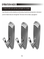
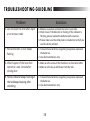
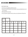
1
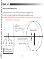
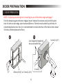
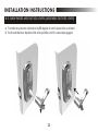
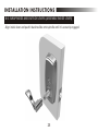
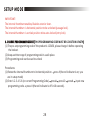
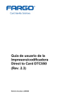
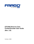
ELECTRONIC KEYPAD LEVER LOCK
User's Guide
IMPORTANT SAFETY INSTRUCTION
WARNING
1. To prevent damage to the finish, DO NOT use any abrasives, sharp objects or harsh chemical
products containing alcohol, petroleum solvents, acids or acetone to clean this lockset.
2. To prevent damage to the sensitive electronic components, DO NOT allow any liquids to enter
lockset while installing or cleaning.
CAUTION !
1. Do not attempt to disassemble any internal components of this lockset as this WILL void the
limited warranty.
2. Do not drop or hit /strike the lockset as excessive shock may result in permanent damage.
3. Do not use sharp objects to press key buttons.
4. It is STRONGLY recommended that you always create a written backup of the programming code
and individual user codes. Please use the last page of this booklet as your reference.
5. For your Security, please remember to change this lockset's factory default programming code
to a PERSONAL programming code prior to normal day to day use of this product (See Page 28).
6. It is STRONGLY recommended that you use only ALKALINE BATTERIES to operate this product.
1
CONTENTS
INSTALLATION INSTRUCTIONS
1. COMPONENTS
TEMPLATE
2. DOOR PREPARATION
3. LATCH INSTALLATION
4. STRIKE PLATE INSTALLATION
5. LEVER DIRECTION DETERMINATION
6-1. TO RESET DIRECTION OF INSIDE LEVER
6-2. TO RESET DIRECTION OF OUTSIDE LEVER
7-1. MOUNTING EXTERIOR ASSEMBLY
7-2. PREPARING TO MOUNT INTERIOR ASSEMBLY
7-3. REMOVING DECORATIVE COVER
7-4. MOUNTING INTERIOR ASSEMBLY
7-5. BATTERY INSTALLATION
7-6. REINSTALL LEVER
8-1. EXCHANGE OF LEVER
8-2. EXCHANGE OF LEVER (REMOVAL OF INSIDE LEVER)
8-3. EXCHANGE OF LEVER (REMOVAL OF OUTSIDE LEVER)
8-4. SWAP INSIDE AND OUTSIDE LEVERS (REMOVAL OF CYLINDER)
8-5. SWAP INSIDE AND OUTSIDE LEVERS (ASSEMBLE OUTSIDE LEVER)
8-6. SWAP INSIDE AND OUTSIDE LEVERS (ASSEMBLE INSIDE LEVER)
2
5
6
CONTENTS
MAIN OPERATING INSTRUCTIONS
SETUP MODE
1. CHANGE PROGRAMMING CODE
2. ADD A USER CODE
3. DELETE INDIVIDUAL EXISTING USER CODE
4. DELETE ALL THE EXISTING USER CODES AT ONCE
5. DISABLE ALL THE EXISTING USER CODES (VACATION MODE)
6. DISABLE BUTTON SOUND (MUTE MODE)
7. SETTING AUTO-LOCK TIME DELAY
8. RESTORE FACTORY SETTING
OPERATION MODE
1.TO ACTIVATE AUTO-LOCKING (AUTOMATIC RE-LOCKING)
2. TO OPEN (UNLOCK) THE DOOR
3. TO DEACTIVATE AUTO-LOCKING (AUTOMATIC RE-LOCKING)
TROUBLESHOOTING GUIDELINE
DATA RECORDS
DECLARATION AND SAFETY STATEMENTS
3
INSTALLATION INSTRUCTIONS
1. COMPONENTS
A. Key
B. Exterior Assembly
C. Mounting Plate
D. Interior Assembly
E. Decorative Cover
F. Battery Pack Cover
G. Lever
H. 5/16''(7.8mm) Screw (2)
E
I. 1-1 /4'' (32mm) Screw (2)
J. Latch
K. 6/8''(19.2mm) Wood Screw (4)
L. Strike
M. Dust Box
B
C
D
A
F
J
I
H
K
L
M
G
4
TEMPLATE
IMPORTANT BEFORE PROCEEDING
1. Remove lever lock, or do not install lever lock prior to painting your door.
2. Do not let any water or liquid into the lockset during installation process.
NOTE:MEASUREMENTS BELOW ARE JUST A GUIDELINE. Please measure your door to determine
the exact center of your door edge.
Fold here
Place on door edge
Backset 60mm(2-3/8'')
51
45
40 35
2''
1-3/4''
1-9/16'' 1-3/8''
Backset 70mm(2-3/4'')
Drill 1''(25mm) hole
at center of door edge
5
O54mm(2-1/8'')
DOOR PREPARATION
2. DOOR PREPARATION
NOTE: If replacing an existing lock or installing in a pre-drilled door, begin with page 7.
Fold the template against the door edge as shown in below illustration, mark and drill a pilot
hole for latch on door edge, select backset (60mm or 70mm) to mark and drill a pilot hole for
selected backset on door face. (It is recommended to mark centerline of the hole on door about
36 inches (914mm) above the floor. )
A
B
Use Diagram of spade bit
here and not Drill bit
25mm(1'')
60mm(2-3/8'') or 70mm(2-3/4'')
6
54mm(2-1/8'')
INSTALLATION INSTRUCTIONS
3. LATCH INSTALLATION
60mm(2-3/8'')
Drive-shaft
B. Push the drive-shaft forward for adjustment to 60mm(2-3/8'').
70mm(2-3/4'')
Drive-shaft
A. Pull the drive-shaft backward for adjustment to 70mm(2-3/4'').
7
INSTALLATION INSTRUCTIONS
3. LATCH INSTALLATION
A. Insert the latch into the latch hole. Using the faceplate as a pattern, TRACE a line along the out
edge of the faceplate and chisel a 4mm (1/8") slot in the marked out area. Face plate should fit
flush with door edge.
B. Insert the latch into the latch hole and fasten with screws.
A
B
Show pencil marking outer edge of latch faceplate with Dotted lined
directional arrows as you do not just carve out the screw holes
8
INSTALLATION INSTRUCTIONS
4. STRIKE PLATE INSTALLATION
A. Placing the strike plate on the door frame, TRACE a line along the out edge of the strike plate
and chisel a 3mm (1/8") slot in the marked out area.
B. Chisel out a hole measuring 32 x 24 x 13mm (1-1/4''X1''X1/2'') in association with the size of the
dust box.
C. Fasten the strike and dust box with screws.
Dust box
Strike
Door frame
9
INSTALLATION INSTRUCTIONS
5. LEVER DIRECTION DETERMINATION
NOTE: Do not install the lock when the lever is at vertical position.
Before lock installation, please determine the inside lever direction according to the opening
direction of door as shown.
10
INSTALLATION INSTRUCTIONS
5. LEVER DIRECTION DETERMINATION
NOTE: Do not install the lock when the lever is at vertical position.
Before lock installation, please determine the outside lever direction according to the opening
direction of door as shown.
11
INSTALLATION INSTRUCTIONS
6-1. TO RESET DIRECTION OF INSIDE LEVER
Press the button below ''SWITCH'' mark of the interior assembly to free inside lever and turn it
upward then down to the correct horizontal direction with the door. Lever will be fixed in position
after a sound of ''click''. Follow the page 10 to determine the direction of the lever.
Button
12
INSTALLATION INSTRUCTIONS
6-2. TO RESET DIRECTION OF OUTSIDE LEVER
Use a screwdriver to press the button in the hole below ''SWITCH'' mark of the exterior assembly
to free outside lever and turn it upward and then down to the correct horizontal direction with
the door. Lever will be fixed in position after a sound of ''click''. Follow the page 11 to determine
the direction of the lever.
13
INSTALLATION INSTRUCTIONS
7-1. MOUNTING EXTERIOR ASSEMBLY
A. Slide the spindle and screw posts through the latch and thread the cable under the latch.
B. Thread the cable through the rectangular hole in the mounting plate and combine the posts of
the mounting plate and the exterior assembly.
C. Fasten the mounting plate with 2 screws (32mm or 1 1/4'') while ensuring the exterior assembly
is held in the ''true vertical'' position on door face.
NOTE: Exterior assembly will not sit completely flush with door face until screws are tightened
completely as there are 2'' anchoring spikes'' which prevent the exterior assembly from
shifting/wobbling during usage.
Mounting plate
A
B
C
Cable
14
INSTALLATION INSTRUCTIONS
7-2. PREPARING TO MOUNT INTERIOR ASSEMBLY
A. Remove battery pack cover by pushing it up to the top position.(Please follow two steps )
B. Remove the lever by inserting the catch tool into the access hole and depressing to release
catch while gently pulling on lever. Once catch has been released, remove the catch tool from
the access hole to allow the lever to pull off completely.(Please follow two steps )
C. Follow the steps on page 16 to remove the decorative cover.
A
Battery pack cover
B
C
(2)Two step
(1) One step
Catch tool
(2)Two step
(1) One step
Decorative cover
15
INSTALLATION INSTRUCTIONS
7-3. REMOVING DECORATIVE COVER
A. Remove decorative cover by holding fingers at cover's edges as shown in photo A.
B. Use thumbs to press ''THUMBTURN'' as shown in photo B and photo C.
B
C
A
16
INSTALLATION INSTRUCTIONS
7-4. MOUNTING INTERIOR ASSEMBLY
A. Insert the cable into the connector port firmly with blue wire just under the red black wires of
the port as shown.
B. Slide the interior assembly onto square spindle of the exterior assembly.
C. Fasten the interior assembly on the mounting plate with 2 screws (7.8mm or 0.3'').
A
B
Blue wire
Interior assembly
17
INSTALLATION INSTRUCTIONS
7-5. BATTERY INSTALLATION
A. Snap the decorative cover back onto the interior assembly.
B. Place four alkaline batteries into the battery pack. Following the imprinted '' +/- '' guide.
C. Replace the battery pack cover as shown.
A
C
B
18
INSTALLATION INSTRUCTIONS
7-6. REINSTALL LEVER
Reinstall the lever after the decorative cover is snapped back onto the interior assembly.
NOTE: If you follow page 10-13 to change inside and outside levers to proper direction,
you can skip the following instructions about exchange of lever to setup mode
started in page 28.
19
INSTALLATION INSTRUCTIONS
8-1. EXCHANGE OF LEVER
For lever removal and assembly process, please see page 21-25.
20
INSTALLATION INSTRUCTIONS
8-2. EXCHANGE OF LEVER (REMOVAL OF INSIDE LEVER)
Insert the catch tool into the access hole on the lever. Once the lever is released, remove the
catch tool and pull the lever off.
Catch tool
21
INSTALLATION INSTRUCTIONS
8-3. EXCHANGE OF LEVER (REMOVAL OF OUTSIDE LEVER)
A. Insert the key horizontally and turn counter-clockwise 90 degrees.
B. Insert the catch tool into the access hole on the lever. Once the lever is released, remove the
catch tool and pull the lever off.
NOTE: This step is required if you are rekeying the lock.
A
B
22
INSTALLATION INSTRUCTIONS
8-4. SWAP INSIDE AND OUTSIDE LEVERS (REMOVAL OF CYLINDER)
A. With lever removed, withdraw the key.
B. Slide the cylinder retaining collar off the shank of the lever.
C. Remove the cylinder.
D. Insert cylinder into the other lever. Align the tab of the cylinder retaining collar with the slot of
lever shank and push it back to secure cylinder in place.
A
B
Protrusion
The slot of the lever
D
C
23
INSTALLATION INSTRUCTIONS
8-5. SWAP INSIDE AND OUTSIDE LEVERS (ASSEMBLE OUTSIDE LEVER)
A. Turn the key counter-clockwise by 90 degree to vertical position as shown.
B. Push outside lever back to slide onto spindle until it is securely engaged.
24
INSTALLATION INSTRUCTIONS
8-6. SWAP INSIDE AND OUTSIDE LEVERS (ASSEMBLE INSIDE LEVER)
Align inside lever and push it back to slide onto spindle until it is securely engaged.
25
MAIN OPERATING INSTRUCTIONS
1.Indicator
4.Confirm Button
2.Keypad
6.Thumbturn
(Auto-Locked/
Unlocked switch)
3.Cancel Button
7.Low Battery Indicator
5.Key Override
21
26
MAIN OPERATING INSTRUCTIONS
27
SETUP MODE
IMPORTANT:
The internal thumbturn enables/disables exterior lever.
The internal thumbturn is horizontal position to be unlocked (passage lock).
The internal thumbturn is vertical position to be auto-locked (entry lock).
1. CHANGE PROGRAMMING CODE (THIS PROGRAMMING CODE MUST BE 6-DIGITS IN LENGTH)
(1) The pre-set programming code of the product is 123456, please change it before operating
the lockset.
(2) Keep a written copy of programming code in a safe place.
(3) Programming code can be used to unlock
Procedures:
(1) Rotate the internal thumbturn to horizontal position press # (the red indicator is on, you
are in setup mode)
(2) Enter 1-2-3-4-5-6 (or current Programming Code) press# press10 press# input new
programming code press # (the red indicator is off in 10 sceonds).
28
SETUP MODE
2. ADD A USER CODE (MAXIMUM 100 SETS USER CODES WITH 4-8 DIGITS IN LENGTH.)
Procedures:
(1) Rotate the internal thumbturn to horizontal position press # (the red indicator is on, you
are in setup mode)
(2) Input programming code press# press 20 press# enter new user code press #
enter new user code press # ...may input 100 sets of user code consecutively (the red
indicator is off in 10 seconds).
(If a number of passwords are to be added at the same time, enter new password and press #
prior to the indicator light timing out 10 seconds after the last press of a keypad button.)
3. DELETE INDIVIDUAL EXISTING USER CODE
Procedures
(1)Rotate the internal thumbturn to horizontal position press # (the red indicator is on, you
are in setup mode)
(2) Input programming code
press# press 30 press# enter existing user code to be
deleted
repeat pressing # and entering existing user code to be deleted consecutively
until each set of user code is deleted. (the red indicator is off in 10 seconds).
(if multiple sets of user codes are to be deleted at the same time, enter each user code to be
deleted and press # repeatedly prior to the indicator light timing out 10 seconds after the
last press of a keypad button.
29
SETUP MODE
4. DELETE ALL THE EXISTING USER CODES AT ONCE
Procedures
(1) Rotate the internal thumbturn to horizontal position press # (the red indicator is on, you
are in setup mode)
(2) Input programming code press# press 40 press# press and hold C (for 3 seconds)
until a beep is heard.
(This will delete all the user codes EXCEPT the programming code)
5.DISABLE ALL THE EXISTING USER CODES (VACATION MODE)
Procedures
(1) Rotate the internal thumbturn to horizontal position
press # (the red indicator is on, you
are in setup mode)
(2) Input programming code press# press 50 press#.
(Please repeat the above procedures to enable all the user codes)
NOTE: If you will be away from home for vacation, please use vacation mode to prevent anyone
accessing your lock and this will just make the codes Temporarily "INACTIVE", not DELETE
them from the unit.
30
SETUP MODE
6.DISABLE BUTTON SOUND (MUTE MODE)
Procedures
(1) Rotate the internal thumbturn to horizontal position
press # (the red indicator is on, you
are in setup mode)
(2) Input programming code press# press 60 press#.
(Please repeat the above procedures to enable the button sound)
7. SETTING AUTO-LOCK TIME DELAY (DEFAULT VALUE IS 5 SECONDS)
Procedures
(1) Rotate the internal thumbturn to horizontal position press # (the red indicator is on, you
are in setup mode)
(2) Input programming code
press# press 70 press# press the seconds for delay time
press# (the red indicator is off in 10 seconds).
of auto-locking (5-90)
NOTE: Do not enter leading zeros - use''5'' not''05''.
8.RESTORED FACTORY SETTING
Procedures
Rotate internal thumbturn to horizontal position remove any of the batteries
press and
hold # until all batteries are installed again
reset is finished when the lock beeps a long
beep of 3 seconds and a short beep.
(Such action will delete all the stored user codes, the programming code will be reset to the
default code 123456. Please re-change the programming code for the safety purpose.
31
OPERATION MODE
1.
TO ACTIVATE
10-3.
TO LOCK AUTO-LOCKING (AUTOMATIC RE-LOCKING)
A. Use a flat tool to turn the thumbturn on the inside to vertical position as shown to activate
auto-locking mode, i.e., this device will be relocked automatically in 5 seconds (default value)
after unlocking. Then outside lever is free turning without retracting latch to open the door.
B. Turn the thumbturn on the inside to horizontal position as shown to deactivate auto-locking
mode.
NOTE: Must turn the thumbturn to vertical (auto-locked) position while completing setup mode.
B
A
Horizontal (arrow) position is unlocked
Vertical (arrow) position is auto-locked
32
OPERATION MODE
2. TO OPEN (UNLOCK) THE DOOR
A. Enter the correct user code or programming code.
B. Upon the green indicator light on and a short beep heard, turn the outside lever to unlock.
33
OPERATION MODE
3. TO DEACTIVATE AUTO-LOCKING (AUTOMATIC RE-LOCKING)
Use a flat tool to turn the slotted turn on the inside as shown from vertical position to horizontal
position to deactivate auto-locking mode. The device is then served as a passage lever.
34
TROUBLESHOOTING GUIDELINE
Problem
Solutions
A. Keypad does not respond
1. Check to see if the batteries are properly installed.
2. Check to see if the indicator is flashing. It means "the
battery is low" if the indicator keeps flashing.
3. Make sure the cable is well-connected to the port.
4. Please contact us if such problem could not be solved.
B. Can not change programming code
1. Complete the "CHANGE PROGRAMMING CODE" process by
inputting codes within 10 seconds.
2. Make sure you have entered the new programming code
twice correctly or go back to the factory setting (refer to
page 31) again.
3. Please contact us if such problem could not be solved.
C. Can not delete all the existing user
codes at once
1. Make sure all codes are entered within 10 seconds.
2. Make sure you have entered the correct programming code.
3. Cancel button should be pressed and held for 3 seconds at
least.
1. Make sure all codes are entered within 10 seconds.
2. Make sure you have entered the correct programming code.
3. The new user code will not be accepted if 100 user codes
are already stored in the memory.
D. Cannot add a new user code.
35
TROUBLESHOOTING GUIDELINE
Problem
E. Can not open the door after input
a correct user code
F. Yellow indicator is on or keeps
flashing
Solutions
1. Make sure you have entered the correct user code.
2. Check to see if the indicator is flashing. If the indicator is
flashing, please replace the batteries with new ones.
3. Please make sure the strike plate is installed correctly if you
see the latch is jammed.
1. It means these batteries are getting low, please replace all
the batteries.
2. Use alkaline batteries only.
G. What happens if the lever lock
cannot be auto- locked after
closing door
1. Make sure the arrow of the thumbturn is directed to LOCK.
2. Make sure the key is withdrawn from the lock.
H. Yellow indicator keeps flashing or
the lock keeps beeping after
unlocking.
1. It means these batteries are getting low, please replace all
the batteries.
2. Use alkaline batteries only.
36
DATA RECORDS
SECURITY INSTRUCTIONS
1. Do not share your programming code with anyone else.
2. Keep a written copy of all valid user codes in safe place. (You may use the table below to record
your information)
3. Code capacity: 100 sets maximum.
4. You are advised to re-program all codes if you lost any security information of the lever lock.
PROGRAMMING
CODE
NAME
CODE
NAME
CODE
37
NAME
CODE
FEDERAL COMMUNICATIONS COMMISSION STATEMENT
This device complies with Part 15 of the FCC. Operation is subject to the following two conditions:
(1) this device may not cause harmful interference, and (2) this device must accept any
interference received, including interference that may cause undesired operation.
Changes or modifications not expressly approved by the party responsible for compliance could
void the user's authority to operate the equipment.
NOTE: This equipment has been tested and found to comply with the limits for a Class B digital device,
pursuant to part 15 of the FCC Rules. These limits are designed to provide reasonable protection
against harmful interference in a residential installation. This equipment generates, uses and can
radiate radio frequency energy and, if not installed and used in accordance with the instructions, may
cause harmful interference to radio communications. However, there is no guarantee that interference
will not occur in a particular installation. If this equipment does cause harmful interference to radio or
television reception, which can be determined by turning the equipment off and on, the user is
encouraged to try to correct the interference by one or more of the following measures:
- Reorient or relocate the receiving antenna.
- Increase the separation between the equipment and receiver.
- Connect the equipment into an outlet on a circuit different from that to which the receiver is
connected.
- Consult the dealer or an experienced radio/TV technician for help.
38
IC REGULATIONS
This Class B digital apparatus complies with Canadian ICES-003 .
Cet appareil numerique de la classe B est conforme a la norme NMB-003 du Canada.
This device complies with Industry Canada licence-exempt RSS-210 standard. Operation is subject
to the following two conditions: (1) this device may not cause harmful interference, and (2) this
device must accept any interference received, including interference that may cause undesired
operation of the device.
39
Rev. 12/05-00
G36-L000012