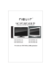
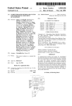
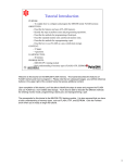
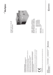
1
XL36
Programming
Adapter Board
User's Manual
How to Reach Us:
Home Page:
www.freescale.com
E-mail:
[email protected]
Document Edition
Date
USA/Europe or Locations Not Listed:
Freescale Semiconductor
M68XL36PABUM/D
Technical Information Center, CH370
1300 N. Alma School Road
Chandler, Arizona 85224
+1-800-521-6274 or +1-480-768-2130
[email protected]
April 1998
Europe, Middle East, and Africa:
Freescale Halbleiter Deutschland GmbH
Motorola reserves the right to make changes without further notice to any
Technical Information Center
products herein to improve reliability, function, or design. Motorola does not
Schatzbogen 7
81829 Muenchen, Germany
assume any liability arising out of the application or use of any product or circuit
+44 1296 380 456 (English)
described herein; neither does it convey any license under its patent rights nor
+46 8 52200080 (English)
the rights of others. Motorola products are not designed, intended, or
+49 89 92103 559 (German)
+33 1 69 35 48 48 (French)
authorized for use as components in systems intended for surgical implant into
[email protected]
the body, or other applications intended to support or sustain life, or for any
Information
in this of
document
is provided product
solely to enable
system
and software
other application in which
the failure
the Motorola
could
create
a
Japan:
to use Freescale Semiconductor products. There are no express or
where personalimplementers
injury
or
death
may
occur.
Should
Buyer
purchase
or
Freescale Semiconductor Japansituation
Ltd.
implied copyright licenses granted hereunder to design or fabricate any integrated
Headquarters
circuits
integrated
circuits basedor
onunauthorized
the information in this
document.
use Motorola products for
anyorsuch
unintended
application,
ARCO Tower 15F
Freescale Semiconductor reserves the right to make changes without further notice to
Buyer shall indemnify and
hold Motorola and its officers, employees,
any products herein. Freescale Semiconductor makes no warranty, representation or
1-8-1, Shimo-Meguro, Meguro-ku,
guarantee
regarding the
suitability of
its products
any particular
purpose, nor does
subsidiaries, affiliates, and
distributors
harmless
against
allforclaims,
costs,
Tokyo 153-0064
Freescale Semiconductor assume any liability arising out of the application or use of
Japan
damages, and expenses,
and
reasonable
attorney
fees
arising
out
of,
directly
any product or circuit, and specifically disclaims any and all liability, including without
0120 191014 or +81 3 5437 9125
consequential
or incidental
damages. “Typical”
parameters
or indirectly, any claim oflimitation
personal
injury or
death associated
with
such which may be
[email protected]
provided in Freescale Semiconductor data sheets and/or specifications can and do
unintended or unauthorized
use, even if such claim alleges that Motorola was
vary in different applications and actual performance may vary over time. All operating
Asia/Pacific:
negligent regarding the design
orincluding
manufacture
the
part. for each customer application by
parameters,
“Typicals” of
must
be validated
customer’s technical experts. Freescale Semiconductor does not convey any license
Freescale Semiconductor Hong Kong Ltd.
under its patent rights nor the rights of others. Freescale Semiconductor products are
Technical Information Center
Motorola, the Motorola logo,
and MCUscribe
are registered
trademarks
of intended for
not designed,
intended, or authorized
for use as components
in systems
2 Dai King Street
surgical
implant
intoand
the body,
or other applications
intended to support
or sustain life,
Motorola
Inc.
Windows,
Windows
NT,
Windows
95
are
trademarks
of
Tai Po Industrial Estate
or for any other application in which the failure of the Freescale Semiconductor product
Tai Po, N.T., Hong Kong
Microsoft Corporation. Adobe
and
Acrobat
Reader
are
trademarks
of
Adobe
could create a situation where personal injury or death may occur. Should Buyer
+800 2666 8080
purchase
use Freescale Semiconductor
products of
for any
such
unintended or
Systems Incorporated. All
otherortrademarks
are the property
their
respective
[email protected]
unauthorized application, Buyer shall indemnify and hold Freescale Semiconductor
holders.
and its officers, employees, subsidiaries, affiliates, and distributors harmless against all
claims, costs, damages, and expenses, and reasonable attorney fees arising out of,
For Literature Requests Only:
or indirectly, any claim of personal
injury
or death associated with such
Freescale Semiconductor Literature
Distribution
Motorola
Inc.Center
is an Equaldirectly
Opportunity/Affirmative
Action
Employer.
unintended or unauthorized use, even if such claim alleges that Freescale
P.O. Box 5405
Semiconductor was negligent regarding the design or manufacture of the part.
Denver, Colorado 80217
©
1998
by
Motorola,
Inc.
All Rights Reserved.
1-800-441-2447 or 303-675-2140
Fax: 303-675-2150
[email protected]
Motorola
6501 William Cannon Drive West
Austin, Texas 78735 USA
2
User’s Manual for the M68PAL908XL36 Programming Adapter Board
Contents
1
Getting Started
Installing the MCUscribe application and personality files
Installed files
6
6
Installing Acrobat Reader 7
Inserting XL36 programming adapter boards
Inserting XL36 MCUs
7
8
Disconnecting power before inserting an MCU 8
Inserting a QFP MCU 9
Inserting an SDIP MCU 10
2
Using the XL36 Programming Adapter Board
XL36 devices and mask sets
12
MCU memory configuration
13
908XL36 MCU memory
13
708XL36-secured MCU memory
Adjusting the device supply voltage
Restrictions and limitations
14
14
16
User’s Manual for the M68PAL908XL36 Programming Adapter Board
3
CONTENTS
3
Support
Opening additional online documentation
Contacting customer support
4
18
19
User’s Manual for the M68PAL908XL36 Programming Adapter Board
1
T
Getting Started
Who needs to read the XL36 Programming Adapter Board
User’s Manual?
Refer to the XL36 Programming Adapter Board User’s Manual if
you have purchased an XL36 programming adapter board (PAB),
and want information about:
■
Installing software and setting up the XL36 PAB for use
■
XL36-specific operation instructions
■
Getting additional support
This chapter explains how to install the software that comes with your
XL36 PAB, and how to plug in the XL36 PAB and the MCUs it supports.
XL36 Programming Adapter Board User’s Manual
5
GETTING STARTED
Installing the MCUscribe application and personality files
The XL36 PAB comes with the latest version of the MCUscribe application
(for Windows® NT and Windows 95). First, install the software:
Insert the first MCUscribe diskette in your floppy drive, and enter
a:\setup.exe in the Windows Run dialog box. The installation setup
program opens.
Follow the instructions to install the software in a folder of your choice. The
installation program places all the MCUscribe files in one folder. Using a
single folder expedites selection of the MCU and S-record files, so that you
can start programming more quickly.
Installed files
These files are installed on your host system:
■
MCUscribe.exe — Windows executable file for the MCUscribe
application—the interface you use to communicate with the SPGMR08,
and to program MCU memory.
■
.mmp files — The personality files that supply the SPGMR08 with MCU
configuration and memory map information. 908XL36.mmp and
708XL36.mmp are the personality files for XL36-supported MCUs.
■
MCUscribe.hlp and MCUscribe.cnt — Online help for using the
MCUscribe application.
■
MCUscribe.pdf — Serial Programmer for HC08 User’s
Manual. Instructions for using the MCUscribe application (help
information in an Acrobat-format user’s manual).
■
QStart08.pdf — SPGMR08 QuickStart Guide. A streamlined guide (in
Acrobat format) to setting up SPGMR08 hardware and software.
■
PABXL36.pdf — XL36 Programming Adapter Board User’s Manual.
A short manual (in Acrobat format) that contains specfic instructions for
setting up and using the XL36 PAB. The software may also include user
manuals for other PABs.
■
readme.txt — Release notes in ASCII format (text from QStart08.pdf)
For tips about opening online support documents, see page 18.
6
XL36 Programming Adapter Board User’s Manual
GETTING STARTED
Installing Acrobat Reader
You must have Acrobat Reader™ installed on your host system in order to
view and print the Serial Programmer for HC08 User’s Manual and other
Acrobat-format support documents. The Reader is supplied on a separate set
of diskettes. To install the Reader:
Insert the first Reader diskette in your floppy drive, and enter
a:\setup.exe in the Windows Run dialog box. The installation setup
program opens. Follow the instructions to install the software in a folder of
your choice.
Inserting XL36 programming adapter boards
To use the XL36 programming adapter board, plug the PAB onto the
SPGMR08 base unit (as shown in the illustration below). The PAB works
when installed in either direction on the SPGMR08 base unit. That is, the
connector on the base unit labeled Pin 1 can accept either connector of the
adapter board.
QFP device
socket case,
with lid closed
SDIP device socket
1
A
ER
L
RO
TO
MO
XL36 programming
adapter board
GE
MM 1 T.
LTA T RA
VO DJUSROG 3 ST P
A P
TE
L
IA
08
C
68H
SER
M
EMR
STWE
SY
PO
N
PI
ETR
E
CK
W
SO
PO
1
A
L
RO
O
OT
Pin 1
M
+
OR
AT
SPGMR08
base unit
XL36 Programming Adapter Board User’s Manual
5V
UL
EM
7
GETTING STARTED
Inserting XL36 MCUs
Disconnecting power before inserting an MCU
If power is disconnected, you can insert or remove MCUs freely. However, if
you are in an MCUscribe session, make sure the yellow Socket Power light
is off before you handle the MCU. MCUs can be damaged by power surges
during installation.
If the Socket Power light is on, click the Power Off button in the MCUscribe
Control Panel. Socket power is disconnected, and the yellow Socket Power
light goes off.
8
XL36 Programming Adapter Board User’s Manual
GETTING STARTED
Inserting a QFP MCU
The illustration below shows a QFP MCU ready to be inserted in the PAB:
1 Open the socket case by lifting the latch on the left.
2 Insert the MCU, matching the MCU’s pin 1 with the socket’s pin 1. The
marked corner of the MCU identifies the location of pin 1. If you turn the
PAB so that the Motorola logo is at the bottom, pin 1 is in the socket’s
upper left corner. (The printed number 1 on the back side of the
programming adapter board corresponds to the location of the socket’s
pin 1.)
Note: Motorola recommends that you use a vacuum pen or other
appropriate tool to handle MCUs. Be careful to avoid bending the
pins.
3 Push the socket lid down gently until it snaps shut.
Pin 1 is located at the MCU’s marked
corner. (The marked corner has either a
recessed dot or a clipped edge.)
socket latch
Pin 1 on the socket is in the
upper left corner (when the
PAB is viewed with the
Motorola logo at the bottom).
R
ME
RAM
AL
ERI
08 S
C
68H
G
PRO
EMR
STWE
SY
PO
M
N
PI
ETR
E
CK
W
SO
PO
1
A
L
RO
TO
O
M
GE T
LTA
VO DJUS
A
3
1
T.
TP
TES
A
L
RO
O
OT
M
+
OR
AT
5V
UL
EM
XL36 Programming Adapter Board User’s Manual
9
GETTING STARTED
Inserting an SDIP MCU
The illustration below shows an SDIP MCU ready to be inserted in the PAB:
Insert the MCU, matching the MCU’s pin 1 with the socket’s pin 1. The
marked corner of the MCU identifies the location of pin 1. The printed
number 1 shows the location of the socket’s pin 1.
Note: Motorola recommends that you use a vacuum pen or other
appropriate tool to handle MCUs. Be careful to avoid bending
the pins.
The MCU’s pin 1 is left of the half-moon
depression. The pin 1 corner is also marked
with a recessed dot on some devices.
The socket’s pin 1 is identified
by a 1 printed on the board.
ER
MM
RA
08
C
68H
M
L
RIA
OG
PR
SE
EMR
STWE
SY
PO
N
PI
1
ETR
E
CK
W
SO
PO
1
A
OL
OR
OT
GE
LTA ST
VO DJU
A
3
1
PT.
ST
TE
A
L
RO
O
OT
M
M
+
OR
AT
5V
UL
EM
10
XL36 Programming Adapter Board User’s Manual
2
Using the XL36
Programming Adapter Board
This chapter has specific information about using the M68PAL908XL36
(XL36) programming adapter board. The XL36 PAB enables the
SPGMR08 to program:
■
Flash EEPROM memory ranges of MC68HC908XL36 (908XL36)
microcontroller units (MCUs) in 64-pin Quad Flat Pack (QFP) or
56-pin Shrink DIP (SDIP) package configurations.
■
EPROM memory ranges of MC68HC708XL36 (708XL36) MCUs
in 64-pin Quad Flat Pack (QFP) or 56-pin Shrink DIP (SDIP) package
configurations.
Note: If you need information about support for other XL36 MCU masks,
contact Motorola customer support (see "Contacting customer
support" on page 18).
XL36 Programming Adapter Board User’s Manual
11
USING XL36 PROGRAMMING ADAPTER BOARDS
XL36 Devices and Mask Sets
Selected MCU / Mask
choice
Device
Mask set
Device supply
voltage (VDD)
Personality file
MC68HC908XL36
2H68R
5V ( ± 10%)
908XL36.mmp
908XL36
2H17F
3V ( ± 10%)
708XL36.mmp
708XL36 H17F
3H17F
5V ( ± 10%)
MC68HC708XL36
H68R
The table above lists XL36-supported devices and mask sets, with these
types of corresponding information:
• Device supply voltage (VDD) — The voltage you can use for a particular
device and mask set. For information about testing or changing this
voltage, see "Adjusting the device supply voltage" on page 14.
• Personality file — The files that supply configuration and memory map
data for programming the various XL36-supported MCUs and mask sets.
To program a particular mask set, the corresponding personality file for
that mask set must be installed on the host system.
• Selected MCU/Mask choice — The entry you select during an
MCUscribe session, from the Control Panel’s Selected MCU list
(shown in the illustration below).
12
XL36 Programming Adapter Board User’s Manual
USING XL36 PROGRAMMING ADAPTER BOARDS
MCU memory configuration
908XL36 MCU memory
The 908XL36 MCU has 36 KB of programmable Flash EEPROM memory
and 34 bytes of vector memory. MCUscribe’s Memory Map status box
(shown below) displays the location of the Flash EEPROM memory arrays.
XL36 Programming Adapter Board User’s Manual
13
USING XL36 PROGRAMMING ADAPTER BOARDS
708XL36-secured MCU memory
The 708XL36 MCU has 36 KB of programmable EPROM memory and 34
bytes of vector memory. MCUscribe’s Memory Map status box (shown
below) displays the location of the EPROM memory array.
Adjusting the device supply voltage
You can adjust the device supply voltage (VDD) of the XL36 programming
adapter board to match the voltage in your target application. The XL36
programming adapter board can program MCUs at a range of voltages.
To measure the current device supply voltage, use the test point
(labelled E1):
1 Begin an MCUscribe session, and select the MCU.
Note: To measure device supply voltage, you must first establish
communcations between the software and the MCU.
When the base unit’s yellow Socket Power light is on,
communications are established.
2 Connect a voltmeter to pin 1 (VMCU) and pin 3 (GND—ground). Read
the device supply voltage on the meter.
14
XL36 Programming Adapter Board User’s Manual
USING XL36 PROGRAMMING ADAPTER BOARDS
To change the device supply voltage, turn the screw on top of the
voltmeter with a screwdriver.
The variable resistor is in a blue case, with the words VOLTAGE ADJUST
printed next to it. The test point is marked TEST PT, and printed numbers
identify pin 1 and pin 3.
adjustment screw
Pin 1 (VMCU)
Pin 3 (GND)
E
TAG ST
L
VO ERDJU
MMA
RA
variable resistor
08
8HC
L
RIA
SE
M6
3
OG
PR
EMR
STWE
SY
PO
N
PI
1
T.
TP
S
TE
ETR
E
CK
W
SO
PO
1
A
OL
OR
OT
GE
LTA ST
VO DJU
A
3
1
T.
TP
S
TE
A
L
RO
O
OT
M
M
+
R
TO
LA
5V
U
EM
Note: For more information about voltage ranges appropriate for your
device, see its General Release Specification.
XL36 Programming Adapter Board User’s Manual
15
USING XL36 PROGRAMMING ADAPTER BOARDS
Restrictions and limitations
This restriction applies to the XL36 programming adapter board:
908XL36 PAB programming voltage: The 908XL36 PAB supports 3 to 5
volt programming; however, the currently available 908XL36 device
functions only at 5 volts.
16
XL36 Programming Adapter Board User’s Manual
3
Support
This chapter explains how to open information resources online,
and how to contact customer support.
Opening additional online documentation
Acrobat-format documents
The MCUscribe application comes with a user’s manual in Acrobat PDF
format, along with the latest version of the Acrobat Reader. There are a
number of online resources (described on page 6) that you can open from
Windows Explorer by double-clicking the file name:
■
Serial Programmer for HC08 User’s Manual — MCUscribe.pdf
(You can also double-click the manual icon in the MCUscribe
program group.)
■
XL36 Programming Adapter Board User’s Manual (online version) —
PABXL36.pdf
■
SPGMR08 QuickStart Guide — QStart08.pdf
XL36 Programming Adapter Board User’s Manual
17
SUPPORT
Online help
Open MCUscribe help directly from the desktop, or from within the
application. (Make sure you have installed the MCUscribe.hlp file and the
MCUscribe.cnt files in the same folder.) You can use any of these methods
to open MCUscribe help:
• Double-click the help icon in the MCUscribe program group.
• Double-click the MCUscribe.hlp file in Windows Explorer, if .hlp files
are associated with Winhlp32.exe.
• Click the Help button in the MCUscribe application, or press F1.
Contacting customer support
Contact the Motorola software support team by telephone, FAX,
regular postal mail, or through the Worldwide Web.
Telephone: 1-800-521-6274 (Customer Focus Center)
Telephone support hours are Monday through Friday,
9:00 a.m. to 5:00 p.m. (CST).
FAX: (602) 302-8157 (Customer Focus Center)
Website: http://www.design-net.com/csic
(68HC05 and 68HC08 8-bit Microcontroller Home Page)
For software upgrades, choose Development Tools,
then Free Software Upgrades/Assemblers.
For more MCU products, see: http://www.mcu.motsps.com
(Embedded Microcontroller Products page)
Mailing address:
18
MCTG Software Support
Motorola, Inc. MD OE45
6501 William Cannon Drive West
Austin, Texas 78735
XL36 Programming Adapter Board User’s Manual