1
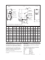
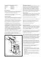
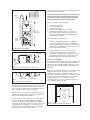
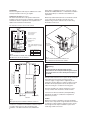
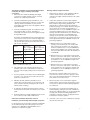
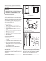
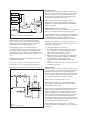
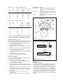
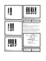
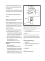
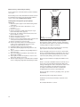
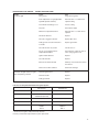
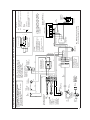
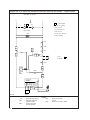
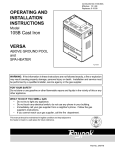
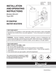
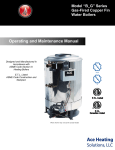
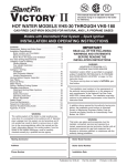
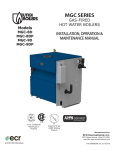
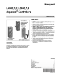
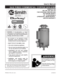
Installation / Service Manual for use by heating contractor Vitogas 050, ECD Series Gas-fired, atmospheric cast iron boiler 65 to 200 MBH / 19 to 59 kW IMPORTANT: READ AND SAVE THESE INSTRUCTIONS FOR FUTURE REFERENCE Warning: If the information in this manual is not followed exactly, a fire or explosion may result causing property damage, personal injury or loss of life. Do not store or use gasoline or other flammable liquids in the vicinity of this or any other appliance. WHAT TO DO IF YOU SMELL GAS ● Do not try to light any appliances. ● Do not touch any electrical switches, do not use any phone in your building. ● Immediately call your gas supplier from a neighbor’s phone. Follow the gas supplier’s instructions. ● If you cannot reach your gas supplier, call the fire department. Installation and service must be performed by a qualified installer, service agency or the gas supplier. WARNING Should overheating occur or the gas supply fail to shut off, do not disconnect the electrical supply to the pump. Instead, shut off the gas supply at a location external to the appliance. 5167 445 v1.1 03/2007 Contents: Page: Technical Data ..........................................................................3 Boiler handling – location..........................................................3 Flushing of existing piping ........................................................4 Vent damper installation ...........................................................4 Closet installation......................................................................5 Combustion air supply ..............................................................6 Installation on combustible floor ...............................................8 Boiler water piping ....................................................................8 Honeywell adjustable high limit aquastat ..................................9 Circulating pump .......................................................................9 Initial system fill.......................................................................10 Boiler venting ..........................................................................11 Gas piping...............................................................................12 Gas pressure – orifice sizes ...................................................12 Main burner.............................................................................13 Blocked vent and flame roll-out switch ...................................14 Wiring......................................................................................14 Electronic thermostat ..............................................................15 System start-up.......................................................................15 Maintenance ...........................................................................15 Troubleshooting ......................................................................17 Lighting instructions ................................................................18 Wiring diagrams ................................................................19, 20 Parts list ................................................................21, 22, 23, 24 Maintenance record ................................................................25 This “Attention” symbol is located beside all important safety recommendations. Please follow the instructions in detail to avoid property damage, severe personal injury, or loss of life. Warning: The installation, adjustment, service, and maintenance of this boiler must be done by a licensed professional service technician who is qualified and experienced in the installation, service, and maintenance of gas-fired hot water boilers. There are no user serviceable parts on the boiler, burner, or control. Failure to heed this warning can cause property damage, severe personal injury, or loss of life. Warning: Improper installation, adjustment, service, or maintenance can cause flue products to flow into living space. Flue products contain poisonous carbon monoxide gas which can cause nausea or asphyxiation resulting in severe personal injury or loss of life. Warning: If flame roll-out or blocked vent switch trips during startup or normal operation, it indicates a hazardous condition to be corrected immediately. Do not attempt to put boiler in operation. Immediately contact a qualified service professional to locate source of problem and correct. Failure to heed this warning could result in property damage, severe personal injury, or loss of life. Do not use this boiler if any part has been under water. Immediately call a qualified service technician to inspect the boiler and to replace any part of the control system and any gas control which has been under water. Do not store chemicals containing chlorine or other corrosive materials near the boiler, such as bleach, cleaning solvents, detergents, acids, hair spray, spray cans, paint thinners, paint, water softener salt, refrigerants. Warning: Installers must follow local regulations with respect to installation of carbon monoxide detectors. Follow manufacturer’s maintenance schedule of boiler. 2 Warning: Before each heating season begins, have the following service and maintenance done by a professional service technician: 1) Boiler heat exchanger inspected and cleaned. 2) Vent system inspected for deterioration, leaks, corrosion, proper draft, and proper operation. Check vent system for compliance with local and national code requirements. Repair or replace as required. 3) Burner inspected and if necessary cleaned to ensure proper combustion and operation. Check for adequate supply of fresh outside combustion and ventilation air. Neglecting to perform necessary maintenance can cause unsafe operation. Warning: Never operate the boiler without an installed venting system which safely vents all products of combustion to the outdoors. The vent system must comply with all applicable local and/or national codes. Improper, incomplete, obstructed, or deteriorated vent systems can present a serious risk of flue gases leaking into living space which could cause carbon monoxide poisoning. Failure to heed this warning can cause severe personal injury or loss of life. Warning: Never operate the boiler without an adequate supply of fresh combustion air. This boiler needs fresh air for safe operation and must be installed so there are provisions for adequate combustion and ventilation air. All combustion and ventilation air must be supplied from the outside. Failure to heed this warning can cause severe personal injury or loss of life. Warning: Shut off all electrical power and turn off gas or oil supply to boiler before performing any service or maintenance on the boiler, burner, or control. Failure to heed this warning could result in electrical shock, serious personal injury or loss of life. Attention: The preferred and safest location for the ECD Series boiler is in a dedicated mechanical room with fresh combustion air intake and ventilation openings made directly to the outside. Vitogas 050, ECD Series Technical Data Cut-away view (left side) Left view Front view B Vent connection Draft hood Boiler supply water 11⁄4˝ (water flows out) Ignition control 24V gas valve 24V vent damper Gas connection 2.5˝ (64) Burner manifold 120V power in 120V 4A max. output to pump 24V thermostat 26.00˝ (660) Transformer 12.25˝ (310) ECD-180/200 45.75˝ (1160mm) ECD-65 to 155 41.75˝ (1060mm) Boiler well for capillaries Boiler return water 11⁄4˝ (water flows in) 2.82˝ (72) A 11.00˝ (279) 17.50˝ (445) 19.75˝ (502) Boiler electrical requirements are 120V, 60 Hz, less than 12A Max. pump amperage is 4A. Use field supplied relay for pumps over 4A. Model CSA input DOE heating capacity CGA output Width “A” Vent Conn. “BØ” Water Content Weight AFUE* Steady State Efficiency ECD-65 65,000 Btu/h 19 kW 53,950 Btu/h 16 kW 350 mm 14˝ 5˝ 1 11⁄4˝ 3 2 9.9 ltr 2.6 USG 106 kg 233lbs 83.7% 83% ECD-80 80,000 Btu/h 23 kW 66,400 Btu/h 19 kW 350 mm 14˝ 5˝ 1 11⁄4˝ 3 2 9.9 ltr 2.6 USG 106 kg 233 lbs 83.5% 83% ECD-100 100,000 Btu/h 29 kW 83,000 Btu/h 24 kW 450 mm 173⁄4˝ 6˝ 1 11⁄4˝ 4 3 13.2 ltr 3.5 USG 130 kg 285 lbs 83.5% 83% ECD-115 115,000 Btu/h 34 kW 95,450 Btu/h 28 kW 450 mm 173⁄4˝ 6˝ 1 11⁄4˝ 4 3 13.2 ltr 3.5 USG 130 kg 285 lbs 83.5% 83% ECD-140 140,000 Btu/h 41 kW 116,200 Btu/h 34 kW 550 mm 213⁄4˝ 7˝ 1 11⁄4˝ 5 4 16.5 ltr 4.3 USG 157 kg 345 lbs 83.5% 83% ECD-155 155,000 Btu/h 45 kW 128,500 Btu/h 38 kW 550 mm 213⁄4˝ 7˝ 1 11⁄4˝ 5 4 16.5 ltr 4.3 USG 157 kg 345 lbs 83.4% 83% ECD-180 180,000 Btu/h 52 kW 149,400 Btu/h 44 kW 654 mm 253⁄4˝ 7˝ 1 11⁄4˝ 6 5 26.8 ltr 7.1 USG 192 kg 423 lbs 83.2% 83% ECD-200 200,000 Btu/h 58 kW 166,000 Btu/h 48 kW 654 mm 253⁄4˝ 7˝ 1 11⁄4˝ 6 5 26.8 ltr 7.1 USG 192 kg 423 lbs 83.0% 83% * With vent damper and intermittent pilot ignition kW figures are approximate Gas Conn. ⁄2˝ ⁄2˝ ⁄2˝ ⁄2˝ ⁄2˝ ⁄2˝ ⁄2˝ ⁄2˝ Water Conn. Cast Burners Iron Sections All sizes available with propane gas. For net IBR rating divide output by 1.15. Electrical requirement 120V, 60Hz, less than 12A Before operating this boiler/burner unit, make sure you fully understand its method of operation. Your heating contractor should always perform the initial start-up and explain the system and the need for regular inspection and maintenance. Boiler handling The boiler is shipped on a wooden pallet in a cardboard crate. Crate and wooden pallet must be removed. Vent damper is shipped separately. The installation must conform to the requirements of the authority having jurisdiction or, in the absence of such requirements, to the National Fuel Gas Code, ANSI Z223.1 (latest edition). In Canada follow CAN/CSA–B149.1 or .2 Installation Codes (latest edition). Boiler location – Minimum clearances to combustibles (all measurements from boiler enclosure) Left side: 150 mm (6˝) Right side: 25 mm (1˝) Front: 150 mm (6˝) Top: 450 mm (18˝) Rear: 25 mm (1˝) Floor: Non-combustible Flue: 150 mm (6˝). Above clearances apply to all ECD boilers. These instructions must be placed in an envelope and affixed to the boiler. 3 Recommended minimum service clearances: Left side: 610 mm (24˝) Right side: 610 mm (24˝) Front: 1220 mm (48˝) Top: 610 mm (24˝) Rear: 610 mm (24˝) Recommendation If boiler is located in a confined space, install main gas shut-off valve (gas cock) and main power supply switch in easily accessible location outside the confined space. The boiler model selected should be based on an accurate heat loss calculation of the building. General information Please read and observe the following instructions carefully before installing the boiler. Install boiler according to these instructions. Flushing of existing piping Before boiler is connected to a piping/heating system which has previously been in service (the ECD is a replacement boiler), the piping system should be flushed thoroughly with water in order to remove sludge or other contaminants, especially in large piping systems such as old gravity pipe systems. Flush from the top of the system with city water pressure. Failure to flush out system can lead to deposits in boiler resulting in boiler failure. This type of failure is not covered under warranty. Boiler foundation Provide a solid, level foundation, capable of supporting the weight of the boiler filled with water, and extending at least 1˝ past the jacket on all sides. Pour a concrete foundation if necessary. The boiler must be installed in an indoor heated space. The boiler should be located near a floor drain. Do not install boilers on carpeting. Install on non-combustible floor. Installation, service and maintenance work must be done by qualified and experienced technicians only. Improper installation, service or maintenance could create a hazard, resulting in property damage, severe personal injury, or loss of life. The ECD Series boiler is for use in closed-loop forced circulation hot water heating systems only. Boiler operation is limited by ASME Code to maximum water pressure of 50 psig and maximum water temperature of 248°F. The vast majority of applications operate below 30 psig and below 194°F. Standard equipment on the ECD boiler includes a 30 psig relief valve and adjustable aquastat with maximum setting of 194°F. An alternate construction is available for operation between 194°F and 248°F. Consult a Viessmann representative for alternate construction before ordering boiler. Necessary permits from local authorities must be obtained before installing boiler. Installation must be made in accordance with local ordinances which may differ from the instructions in this manual. City water Supply Globe Valve valve Return Bypass Backflow preventer Fill valve Air vent Strainer location Air purger Circulator Gas pipe Approved gas shut-off valve Ball valve Diaphragm expansion tank 30 psig pressure relief valve Low water cut-off location ECD boiler Vent connection If the boiler is to be installed on combustible floors or on a mezzanine, it should be equipped with a special base pan. Please reference the Viessmann Price List. Typical boiler piping is shown in Fig. A. Vent damper installation Boilers are sold with a vent damper, packaged separately. The vent damper must be installed on the boiler to meet minimum federal efficiency standards. If possible, install vent damper at the top of the draft hood. Otherwise install vent damper as close to the boiler as possible. The vent damper must be field installed on the boiler. Read the vent damper manufacturer’s instructions before installing the vent damper. Vent damper must be installed as close as possible to the boiler flue outlet. The closing and opening action of the vent damper is driven by a motor. Spring action is not used to move the vent damper blade. Do not force vent damper blade by hand. Forcing the vent damper blade by hand will damage the motor. To observe the vent damper blade move, turn thermostat up and down after the vent damper has been installed. Vent damper blade must be in open position when burner is firing. The vent damper must be installed according to Fig. B. The vent damper may be placed directly on top of the ECD boiler. Ensure that damper blade rotates freely and is not obstructed in any way. Read and save the vent damper manufacturer’s instructions packaged with the vent damper. After vent damper has been installed on boiler connect the vent damper cable using the following instructions. Pressure gage 1. 2. 3. Drain valve Floor drain 4. Level concrete floor pad Fig. A Typical hot water piping system Air flow Remove ECD front panel. Route the end of the vent damper cable with the Molex connector through the plastic strain relief on the ECD left side panel. Attach Molex connector to vent damper motor using the metallic strain relief on the vent damper motor to secure the cable. Unplug the two 3-pole #41 plugs inside the boiler and attach them to the 6-pole plug from the vent damper (see Figs. B, C and D). Dim “A” Molex connector ECD-65, -80 47.75˝ ECD-100, -115 48.25˝ ECD-140, -155 48.75˝ ECD-180, -200 52.75˝ There are no serviceable parts on the vent damper. Defective vent dampers must be replaced. If the side wall vent system is used, the vent damper must not be installed. Refer to separate side wall vent system instructions for series boiler. The side wall vent system must be purchased separately from the ECD boiler. Sequence of operation with vent damper: “A” Effikal vent damper only 1. 2. 3. 4. 5. Thermostat calls for heat. Vent damper blade opens. Pilot sparks and ignites. Pilot is proven and main valve is energized. Main burner and pilot will continue to operate until thermostat is satisfied. Burner may turn off and on in response to the adjustable high limit aquastat (SHL1) setting during a call for heat. If the vent damper becomes defective: Plastic strain relief 1. Follow the vent damper manufacturer’s instructions to leave the vent damper in the “Service” or “Hold Open Damper” (Effikal) mode by using the service switch on the damper motor. Vent damper blade should stay open and boiler should operate normally. 2. If the procedure in #1 does not work, remove vent damper, install transitional piece of vent pipe and disconnect 6-pole plug from 3-pole plugs. Connect the 3pole plugs together as shown in Fig. D. Refer to wiring diagrams. Boiler will operate without vent damper. Fig. B Vent damper harness installation 3-pole burner plug 41 41 41 3-pole control plug 6-pole vent damper plug 3-pole burner plug 41 41 Fig. C Plug connection with vent damper (or power vent) 3-pole control plug Fig. D Plug connection without vent damper Closet/alcove installation Models ECD- (65-155) are approved for closet installation with the clearances shown in Fig.1. Models ECD- (180, 200) are approved for alcove installation with the clearances shown in Figs. E and F. Do not use Models ECD- (180, 200) in closet installations. Please note that the minimum clearance to combustibles listed will apply when the boiler is located in a room large in comparison to the size of the equipment. Please see the Uniform Mechanical Code for definition. If the boiler is installed in a space that does not fit the definition of a “room large in comparison with the size of the equipment”, then it is considered a closet or an alcove installation and the closet or alcove installation instructions apply. The cable must not touch the vent pipe, and any excess cable must be suitably supported with cable clamps screwed to the side of the boiler if required. Refer to wiring diagrams. Do not attach vent damper cable to water or vent pipes. Damper must be in the open position when main burners are operating. The damper position indicator (arrow) must be in a visible location following boiler installation. The venting system must be arranged so that only the ECD boiler is served by the vent damper. Maintain a minimum clearance of 6˝ between the vent damper and combustible construction. There must be provision for service access to the vent damper after the installation. Use sheet metal screws (e.g. #8 x 1⁄2˝) to fasten vent damper to boiler and vent pipe. Thermostat anticipator should be set at 0.8A. 1˝ Top clearance 18˝ 6˝ 1˝ Top view Fig. E Alcove installation for ECD- (180, 200) boiler 5 ATTENTION Follow local regulations with respect to CO detectors. Follow all safety information from LP or gas supplier. Combustion air supply (see Fig. 2) This boiler needs fresh air for safe operation and must be installed so there are provisions for adequate combustion and ventilation air. Refer to requirements of local jurisdictions in addition to the information in this manual. (latest edition) or applicable provisions of the local codes. In Canada follow CAN/CSA-B149.1 or .2 Natural Gas Installation Codes (latest edition) for combustion and ventilation air requirements. Whenever possible install boiler near an outside wall so that it is easy to duct fresh air directly to the boiler area. See example in Fig. 2. Refer to national codes for duct sizing. Round ducts can be used. All combustion air must come from the outside. Vent pipe ECD-(180, 200) Return Supply 18˝ Front of alcove must be removable for service access Outside Ventilation opening 24˝ Exp. tank PRV 1˝ Drain valve Combustion air opening Vent Each opening shall have an area of one square inch per 1000 Btu/h of input Concrete non-combustible floor Left side view Opening size 180 10 x 20 200 10 x 20 6˝ (150mm) Fig. F Alcove installation for ECD- (180, 200) All dimensions shown are minimum ECD Electrical on/off switch for boiler Combustion air ducted from outside Air flow Fig. 2 Boiler located in dedicated mechanical room with combustion air ducted in from outside. Fresh combustion air ventilation openings 2 openings 10 x 20 each 18˝ (458mm) Warning: Failure to provide an adequate supply of fresh combustion air can cause poisonous flue gases to enter living space which can cause severe personal injury or loss of life. Outside air must enter the house to replace the air used by the boiler. When the boiler operates, the burner needs a continuous supply of oxygen which is supplied by the air entering the structure. Without a continuous supply of oxygen the flames will incompletely burn and can allow poisonous carbon monoxide gas to circulate into the living space. ECD-(65-155) 6˝ (150mm) Any home with bathroom or kitchen exhaust fans or heat recovery ventilator units should have outside air intake. 6˝ (150mm) 1˝ (25mm) Side view Fig. 1 ECD- (65-155) Closet installation minimum clearances Provisions for combustion and ventilation air must be made in accordance with section 5.3, Air for Combustion and Ventilation, of the National Fuel Gas Code, ANSI Z223.1 6 You must check with local authorities (municipal building department, gas utility) for combustion air requirements particular to your area. Caution: Whenever your boiler is installed in a structure with airtight features such as vapor barrier or tight insulation, there must be a combustion air duct installed to supply air from the outside even though the boiler may be installed in a space with a volume large relative to the boiler. The following guidelines are from the CSA B149 Code for combustion air supply in buildings with airtight construction: 1. When the boiler is installed in buildings with airtight construction, air supply openings or ducts connected directly to the outside must be installed. Buildings without airtight construction 1. Always have air openings or ducts supplying air directly from the outside. If there is any doubt about the combustion air supply, install ducts directly to the outside for fresh air. 2. For boilers installed above grade and within 2 ft. of an outside wall, openings may be used in lieu of a duct. The openings shall be located within 1 ft. above and 2 ft. horizontally from the burner level of the appliance with the largest Btu/h input. 2. 3. For boilers installed below grade, the combustion air duct must terminate within 1 ft. above, and within 2 ft. horizontally, from the burner level of the appliance having the largest Btu/h input. If the boiler is installed in a confined space within the building (a space with a volume less than 50 ft3 per 1,000 Btu/h of input for all gas burning equipment) then adequate air for combustion must be provided by two permanent openings: one located 6˝ below the ceiling, the other 6˝ above the floor. Each opening shall have a minimum free area of 1 in2 per 1,000 Btu/h of input for all gas burning equipment, but not less than 100 in2. Two openings each with a minimum free area of 200 in2 will be sufficient for the installation of one ECD-200. Larger openings can be used. The volume of the boiler space and the space connected by the air openings must have a volume greater than 50 ft3 per 1,000 Btu/h of input for all gas burning equipment. According to the CSA-B149 Code the following diameters can be used for round corrosion resistant air supply ducts with smooth internal surfaces. Use equivalent lengths of 10 ft. per 90° elbow and 5 ft. per 45° elbow and 15 ft. for a grill or louver. See Table 1. Model a) When the boiler is in a confined space and the openings can be made directly on an outside wall to allow outside air into the boiler room, each opening shall have a minimum area of 1 in2 per 4,000 Btu/h for all gas burning equipment. Two openings each with a free area of 50 in2 will be sufficient for the installation of one ECD-200. Dia. for up to Dia. for up to 20 ft. of equivalent 50 ft. of equivalent length air duct length air duct ECD-65, -80 4˝ 5˝ ECD-100, -115 5˝ 6˝ ECD-140, -155 5˝ 6˝ ECD-180, -200 6˝ 7˝ b) When the boiler is in a confined space and horizontal ducts are connected to crawl spaces or attics which can freely communicate to the outdoors, the openings shall be a minimum of 1 in2 per 2,000 Btu/h of input for all gas burning equipment. Table 1. Combustion air duct sizes c) When the boiler is in a confined space and vertical ducts are connected to crawl spaces or attics which can freely communicate to the outside, the openings shall be a minimum of 1 in2 per 4,000 Btu/h of input for all gas burning equipment. 4. The outside inlet of the combustion air duct must not permit the entry of rain or wind and must not reduce the free area of the air supply opening. It must not be blocked by snow. 5. Corrosion resistant screens must not have individual grids less than 1⁄4˝ x 1⁄4˝. Screens may not reduce the free area required for combustion air. 6. Manually operated combustion air dampers are not allowed. The air opening must be not of a type that could lead to situations where the air supply may be closed off while the burner is running. 3. Wherever possible, it is recommended to supply air directly from the outdoors through wall openings or ducts even if previous experience with fuel burning equipment was satisfactory. 7. A combustion air supply inlet opening from the outdoors shall be located not less than 12 inches above the outside grade. 4. 8. Certified combustion air supply equipment may be used in lieu of a duct to provide outside combustion air. Any change to the construction of the building such as weather-stripping, caulking around cracks, installation of exhaust fans, adding insulation, etc. can prevent adequate air supply and can make the building airtight. When required by construction changes, air supply ducts must be installed for safe boiler operation. 5. If windows or doors are used for combustion air openings, they must be locked open. Viessmann recommends above items 1-8 for all installations, even in buildings without airtight construction. For structures that do not have tight construction and adequate air can infiltrate through cracks and openings in doors and windows refer to ANSI Z223.1 and CSA-B149.1 and .2 guidelines for combustion air supply. When ducts are used they shall be of the same cross sectional area as the free area of the openings to which they connect. The minimum dimension of rectangular air ducts shall be not less than 3 inches. 7 The boiler location must never be under negative pressure. Exhaust fans, attic fans, or dryer fans may cause air to be exhausted at a rate higher than air can enter the structure for safe combustion. 6˝ 6˝ Warning: Never cover the boiler or store debris or other materials near the boiler, or in any way block the flow of adequate fresh air to the boiler. Never cover the combustion air duct. 4˝ Combustible floor Excerpt from our warranty terms Boiler is not covered under any warranty terms for damages resulting from the following: Improper application and installation, installation by unqualified personnel, ignorance of instructions, improper service and maintenance work, incorrect replacement component selection or application, incorrect field wiring. Full warranty applies only when boiler is installed and operated according to instructions and used only with the proper gas and the applicable gas pressures. Note: Minimum base extension 6˝ beyond all sides of boiler enclosure Fig. 3 Suggested base for installation on combustible floor Pressure relief valve Boiler supply connection Please read boiler warranty card. Standard equipment ● Wet base sectional cast iron heat exchanger with stainless steel burners ● Boiler completely assembled with vertical draft diverter ● Electronic ignition ● 24 VAC redundant seat gas valve ● Boiler fully insulated with 11⁄2˝ fiberglass wrap-around blanket ● Boiler control panel with fixed high limit and temperature gage ● Pump aquastat to turn pump on ● One 120/24 VAC transformer ● 30 psig pressure relief valve, pressure gage and fittings ● One cleaning brush ● Adjustable high limit Installation on combustible floor Pressure gage Supply piping to radiation Fig. 4 Pressure relief valve installation (Use fittings supplied in accessory pack) Air vent Air separator Pressure reducing Backflow valve preventer Placement of boiler 1. Verify that base size and material are in conformity with local codes. 2. Locate the base so that the minimum clearances of boiler to combustible materials are maintained as outlined on page 3. 3. Base must be constructed of hollow concrete blocks, minimum height 100 mm (4˝), covered with sheet metal at least 24 ga. thick. 4. The base must extend beyond the boiler enclosure by at least 150 mm (6˝) on all sides. 5. The blocks must be placed to provide an unbroken concrete surface under the boiler, with the hollows running continuously and horizontally to allow air circulation. Fig. 4a Multi-zone system using zone pumps. Piping arrangement for best air elimination (see note on following page) Boiler water piping Install pressure relief valve and pressure gage directly to boiler supply. No isolation valve must be installed between boiler supply and pressure relief valve. Install pressure relief valve as shown in Fig. 4. Before boiler is connected to a piping/heating system which has previously been in service (boiler is a replacement boiler), the piping system should be flushed thoroughly with water in order to remove sludge or other contaminants, especially in large piping systems such as old gravity pipe systems. Water piping must be supported by pipe hangers. Boiler must not support weight of water piping. 8 Check system for pipe leaks, defective valves etc. and make required corrections immediately. Precharged expansion tank PRV C F Pressure gage ECD boiler Be aware that best overall system performance is achieved when all components are properly sized. Sizing of the required circulation pump according to the pipe layout and calculation of a proper volume expansion tank is vital to obtain the system’s peak performance. See Fig. 4a for multi-zone system using pumps. F N Do not use this boiler to directly heat swimming pool water. Use a heat exchanger to separate the boiler water from the pool water. Caution: For underfloor heating applications, an additional immersion or strap-on aquastat must be installed in the low temperature underfloor loop (ahead of the mixing valve) to de-energize the pump and/or boiler to prevent overheating. High water temperatures can damage concrete slabs. Adjustable high limit aquastat (see Fig. 4c) The adjustable high limit aquastat limits the boiler water temperature during a call for heat from the room thermostat or other operating control. It is located behind the front access panel. Honeywell L4008A aquastat or equivalent may be used. Ensure sensing bulb is fully inserted in well, see Fig. 4c. Set to a minimum of 140°F. Never permanently bypass high limit aquastats. Circulating pump The pump aquastat is located behind the control panel. Connect the circulating pump wires to the boiler terminal strip. Circulating pump supplied by others. Failure to connect pump aquastat will significantly shorten life expectancy of boiler heat exchanger. Pump aquastat is factory set at 116°F. Alternate aquastat is available at 104°F. 120V power input Transformer/Relay Viessmann 24V L N G 120V pump output 120V Jumper Thermostat connections 24V 120V pump over 4A N L T T F Fig. 4b Using transformer/relay to switch pumps over 4A current draw. F Field supplied The following lists typical water flow rates for the Atola-ECD boiler series: Flow rate (GPM) Flow rate (GPM) Model for 20°F rise for 30°F rise ECD-65 5.3 3.5 ECD-80 6.6 4.4 ECD-100 8.3 5.5 ECD-115 9.5 6.3 ECD-140 11.6 7.7 ECD-155 12.8 8.5 ECD-180 14.9 9.9 ECD-200 16.6 11.0 The water pressure drop for ECD-(65, 200) is: GPM 10 15 20 Pressure drop (ft. of water) .33 .60 1.20 Refer to wiring diagrams on pages 19, 20 for wiring a pump (less than 4A) to the ECD boiler terminal strip. For pumps greater than 4A use a field supplied switching device to switch separate 120V power to the pump, see Fig 4b. 120V (4A) is switched from the boiler terminal strip when the boiler pump aquastat exceeds its setting. Caution: Do not connect pumps with continuous or inrush currents greater than 4A. For pumps over 4A add a field supplied switching relay. See Fig. 4b for an example. Note to Fig. 4a For multi-zone systems using zone pumps, one pump (usually the one serving the main living area) should be dedicated to operate with the pump aquastat located on the boiler (see wiring diagram). For multi-zone systems a bypass pipe must be installed. See page 10 for bypass piping details. Do not wire more than one thermostat end switch from the zone valves into the boiler thermostat T-T connection. Wiring more than one thermostat into the boiler thermostat T-T connection will lead to burner short cycling, which can cause reduction in life span of the boiler due to probable flue gas condensation. This type of failure is not covered under the boiler warranty. Boiler terminal strip L 120V Caution: The boiler warranty does not cover leaks resulting from corrosion caused by the use of underfloor plastic tubing without an oxygen diffusion barrier. Such systems must have the non-oxygen diffusion barrier tubing separated from the boiler with a heat exchanger. Viessmann recommends the use of underfloor plastic tubing with an oxygen diffusion barrier. Caution: This boiler is not for use in systems where water is constantly or frequently replenished. Minerals such as calcium in makeup water can deposit on heat exchanger causing overheating, and eventually the boiler will leak. This type of failure is not covered by warranty. Water must not be drained from system for use by cleaning personnel. Separate breaker 140 Adjustment screw set to 140°F minimum Fig. 4c Honeywell L4008A adjustable high limit aquastat is located behind access panel Low water cut-off If the ECD boiler is installed above radiation level then a low water cut-off device must be installed. See Fig. 5b for location of low water cut-off device. Note: Flow direction must be as shown in Fig. 5b. Low water cut-off is field supplied. Follow instructions provided with low water cut-off. Heating/ Cooling unit Heating/ Cooling unit Heating/ Cooling unit CP V2 V FC AFV V When required by the authority having jurisdiction, the installation must conform to the Standard for Controls and Safety Devices for Automatically Fired Boilers, ANSI/ASME CSD-1, latest edition. FC V FC V Water chiller Bypass piping (see Fig. 5a and Fig. 5b) In some cases it is necessary to install a bypass. If you find the bypass is not needed, then simply close the bypass valve. V1 Fig. 5a Boiler piping in a heating/cooling application Boiler piping in heating/cooling application The boiler, when used in connection with a refrigeration system, must be installed so the chilled medium is piped in parallel to the boiler with appropriate valves to prevent the chilled medium from entering the boiler (Fig. 5a). Install a bypass in order to prevent flue gas condensation from occurring in the heat exchanger casting and vent system when installing the boiler in a large water volume system (i.e. converted gravity system with tube type cast iron radiators). A bypass is not a substitute for a mixing valve driven by an indoor/outdoor control for proper weather responsive control of an underfloor heating system. 1. 2. The boiler piping system of a hot water heating boiler connected to heating coils located in air handling units where they may be exposed to refrigerated air circulation must be equipped with flow control valves or other automatic means to prevent gravity circulation of the boiler water during the cooling cycle. 3. 4. Check installation instructions of chiller manufacturer carefully for additional requirements. 5. Install full size bypass as shown below. Use valve in bypass and valve in supply line to balance flow so that boiler water temperature quickly reaches 140°F or higher. Use globe valve or ball valve. Bypass line should be minimum 12˝ long. Bypass will lower flow rate through boiler to allow higher average water temperature rise. Water flow will bypass boiler depending on setting of bypass valve. If the bypass is not needed, simply close the bypass valve. The water flow direction must be as shown. Water flows in at bottom and out at top. Cooling season starts: Close valve V1 and open valve V2. Heating season starts: Close valve V2 and open valve V1. 6. A metal tag should be attached to these valves as to purpose. Initial system fill Treatment for boiler feed water should be considered in areas of known problems, such as high mineral content and hardness. In areas where freezing might occur, an antifreeze may be added to the system water to protect the system. Please adhere to the specifications given by the antifreeze manufacturer. Do not use silicate based automotive antifreeze solutions. Install a strainer on return pipe when necessary. Wait for fill water to warm up to room temperature (70°F) before firing boiler. Firing boiler with cold water will stress the casting and could cause failure. 2˝ min. Low water cut-off Fig. 5b Low water cut-off location 10 Please observe that an antifreeze/water mixture may require a backflow preventer within the automatic water feed and influence components such as diaphragm expansion tanks, radiation and pumps selection. A 40% antifreeze content will give freeze-up protection to approximately -10°F (-23.3°C). Do not use antifreeze other than specific brands made for hot water heating systems. System also may contain components which might be negatively affected by antifreeze. Check total system frequently when filled with antifreeze. A field supplied pressure reducing valve (or “fill” valve) is required to reduce the incoming water pressure to between 12 and 15 psig. Boiler venting (Category I) The mounted boiler draft hood must not be altered or modified in the field. The boiler should be located as close to the chimney as possible. The vent connection must be made in the shortest possible way with a minimum quantity of elbows. The ECD boiler draft hood must not support the weight of the chimney. The chimney and vent connectors must be suitably supported to prevent the draft hood from supporting the weight of the chimney. Removal of existing boiler When an existing boiler is removed from a common venting system, the common venting is likely to be too large for proper venting of the appliances remaining connected to it. At the time of removal of an existing boiler, the following steps shall be followed with each appliance remaining connected to the common venting system placed in operation, while the other appliances remaining connected to the common venting system are not in operation. 1. 2. Warning: Improper sizing, maintenance, termination of vent or chimney can cause flue gases to enter living space. Any blockage of vent or chimney by birds’ nests, ice, snow, debris, or other materials can cause flue gases to enter living space. Flue gases entering living space can cause carbon monoxide poisoning which can result in severe personal injury or loss of life. 3. 4. Avoid long horizontal runs of vent pipe. Horizontal runs must be supported by appropriate means to prevent sagging, and should have not less than 1⁄4˝ rise per ft. from the boiler to the vertical vent connection. 5. 6. Metal strapping must be used to support horizontal runs every 3 ft. Use approved vent materials only. For venting purposes, a B-vent may be used. With this boiler installation, it is recommended to install a corrosion resistant approved liner within a masonry or unlined chimney. Observe and follow local rules and regulations. The vent connector of this boiler must not be connected into any portion of mechanical draft systems operating under positive pressure. Based upon proper chimney and breeching size, the boiler may be vented into a chimney/breeching with a direct-fired (atmospheric-fired) gas water heater. Observe national codes, local rules and regulations. In Canada follow CSA B149.1 or .2, in USA follow National Fuel Gas Code ANSI Z223.1. Always use latest edition of national codes for all venting installation requirements. Before connecting boiler to existing chimney, inspect chimney for inside and outside conditions. Deteriorated chimneys are unsafe. Terminate venting system outside with approved termination at least 6 ft. above the boiler. Vent pipe must extend at least 3 ft. above the point where it passes through the roof. Vent termination must be at least 2 ft. higher than any portion of building within 10 ft. horizontal and vent termination must be at least 2 ft. higher than roof peaks within 10 ft. horizontal. 7. Seal any unused openings in the common venting system. Visually inspect the venting system for proper size and horizontal pitch and determine there is no blockage or restriction, leakage, corrosion or other deficiency which would cause an unsafe condition. Insofar as is practical, close all building doors and windows and all doors between the space in which the appliances remaining connected to the common venting system are located and other spaces of the building. Turn on any exhaust fans such as range hoods and bathroom exhausts, so they will operate at maximum speed. Do not operate a summer exhaust fan. Close fireplace dampers. Place in operation the appliance being inspected. Follow the lighting instructions. Adjust thermostat so appliance will operate continuously. Test for spillage at the draft hood relief opening after 5 minutes of main burner operation. Use the flame of a match or a candle. After it has been determined that each appliance remaining connected to the common venting system properly vents when tested as outlined above, return doors, windows, exhaust fans, fireplace dampers and any other gas burning appliance to their previous condition of use. Any improper operation of the common venting system should be corrected so the installation conforms with the National Fuel Gas Code, ANSI Z223.1 – latest edition. When resizing, any portion of the common venting system should be resized to approach the minimum size as determined using the appropriate tables in Appendix G in the National Fuel Gas Code Z223.1 – latest edition. The above steps 1–7 must be followed for new installations involving single or multiple ECD boilers. Side wall vent system A side wall power vent system can be ordered for the ECD boiler. This package includes the appropriate power venter, vent terminal and adaptor fittings for each ECD boiler model, as well as installation instructions. The vent damper must not be installed when the side wall vent system is used. For boilers for connection to gas vents or chimneys, vent installations shall be in accordance with Part 7, Venting of Equipment, of the National Fuel Gas Code, ANSI Z223.1, or applicable provisions of the local building codes. Ignition system Safe lighting and other performance criteria were met with the gas manifold and control assembly provided on the boiler when the boiler underwent tests specified in the ANSI Z21.13/ CSA 4.9 boiler standard. Downdraft problems due to negative building pressure must be corrected. Chimney condensation problems must be corrected. 11 The gas ignition system and components must be protected from water (dripping, spraying, rain etc.) during appliance operation and service (circulator replacement, control replacement, etc.). If boiler has been underwater, all electrical parts must be replaced. Pressure relief valve The pressure valve supplied with this boiler must be installed. Install a pressure relief valve according to Figs. A, 4, 5b. Manual gas shut-off valve Ground joint union Warning: Never cap or plug pressure relief valve opening or discharge pipe. Never install shut-off valve between boiler and pressure relief valve. Failure to heed this warning can cause explosion resulting in property damage, severe personal injury, or loss of life. If pressure relief valve is discharging frequently, locate source of problem and correct. Significant amounts of make-up water will cause mineral deposits in boiler which may lead to failure. This type of failure is not covered under warranty. 3˝ (75mm) minimum A discharge pipe of the same diameter or larger as the pressure relief discharge opening must be rigidly installed directly onto the pressure relief valve. The discharge should extend to the floor drain and end approximately 6˝ above the floor. The discharge pipe end must not be threaded. Do not pipe discharge outdoors. Drip leg Fig. 6 Gas pipe installation The boiler must be isolated from the gas supply piping system by closing its individual manual shut-off valve during any pressure testing of the gas supply piping system at a test pressure equal to or less than 1⁄2 psig (3.5 kPa). Follow instructions supplied with pressure relief valve. Caution: Discharge piping of pressure relief valve must be installed so there will be no danger of scalding personnel. Boiler is standard equipped with 30 psig ASME-rated pressure relief valve. This 30 psig pressure relief valve may be exchanged at the job site with a 50 psig ASME-rated pressure relief valve only by strictly observing the minimum relief valve capacity in lb/h marked on the nameplate. The maximum allowable working pressure is 50 psig. Gas piping Before connecting gas boiler to gas line, install main gas shutoff valve, union, and capped drip leg (see Fig. 6). Unions and manifold have been factory-tested. Leak test must be repeated during initial trial operation of burner by mechanical contractor. Never check for gas leaks with an open flame. Use approved spray liquid or soap water solution for bubble test. Gas pressure – Orifice sizes Natural Gas Minimum gas valve inlet pressure Maximum gas valve inlet pressure Propane Gas Minimum gas valve inlet pressure Maximum gas valve inlet pressure 4.5˝ w.c. 14˝ w.c. 12˝ w.c. 14˝ w.c. Size gas supply piping to boiler according to local utility requirements. Identify the main shut-off valve as such with a tag and familiarize owner of boiler with this valve. Support piping by proper suspension method. Piping must not rest on or be supported by boiler. Flame roll-out switch Burner tubes 13 mm socket Testing – gas pipe The boiler and its gas connection must be leak-tested before placing the boiler in operation. Use only the gas stated on the boiler rating plate. The boiler and its individual shut-off valve must be disconnected from the gas supply piping system during any pressure testing of that system at pressures in excess of 1 ⁄2 psig (3.5 kPa). 12 Manifold attachment screws (2 per side) Pilot burner Fig. 7 Gas manifold removal Manifold pressure test port Manifold orifices – natural gas (1,000 Btu/cu. ft.) Boiler size ECD Orifices required Low Altitude 0-610m 0-2000ft. Orifice size Ø High Altitude 610-1370m 2000-4500ft. Orifice size Ø Gas valve/manifold pressure ˝w.c. 65 80 100 115 140 155 180 200 2 2 3 3 4 4 5 5 2.65 2.95 2.70 2.85 2.75 2.85 2.80 2.95 2.55 2.80 2.60 2.75 2.65 2.80 2.65 2.80 3.5 3.5 3.5 3.5 3.5 3.5 3.5 3.5 Main burner (see Fig. 8) Proper flame: Upper main flame cone with light orange coloring, sharply defined individual flames (Fig. 8). Underfired: Lazy-burning main flame cone, mushy flame appearance throughout, smaller flame sizes than in Fig. 8. Overfired: Increased burner noise, higher flame sizes than in Fig. 8. Main flame cone 1.60 1.80 1.65 1.75 1.70 1.75 1.70 1.80 Low Altitude 0-610m 0-2000ft. Gas valve/manifold pressure ˝w.c. High Altitude 610-1370m 2000-4500ft. Gas valve/manifold pressure ˝w.c. 10˝ 10˝ 10˝ 10˝ 10˝ 10˝ 10˝ 10˝ 9˝ 8˝ 8˝ 8˝ 8˝ 8˝ 8˝ 8˝ All orifice sizes given in mm! Orifice size is stamped onto each orifice for identification. When ordering orifices, state boiler size, type of gas, number of orifices required and orifice size. Gas burner removal (see Fig. 7) The main gas burner manifold with the individual stainless steel burners mounted may be easily removed from the boiler by: 1. Closing the main gas shut-off valve external to boiler. 2. Disconnecting all power to boiler. 3. Removing front cover panel from boiler. 4. Breaking ground joint union before gas valve, remove gas pipe. 5. Disconnecting wiring to gas valve. Disconnect wiring from igniter sensor and ground connection. 6. Loosening manifold bolts. (Do not remove, only loosen). Use socket with extension to access bolts through holes in side panel. 7. Removing burners once manifold is loose. 8. Slide out on an upper angle to remove manifold. Gas input – CAUTION Do not exceed input rating stamped on rating plate of boiler. 1. Close main gas shut-off valve. 2. Disconnect main power supply to boiler. 3. Remove plug (1⁄8˝) on manifold. Install test plug and connect U-tube manometer or equivalent. 4. Place boiler/burner in operation. 5. Read manifold gas pressure and compare with stamped rating on rating plate. If necessary, adjust pressure on gas valve. If using meter clocking method: Ensure there is no gas flow through the meter other than to the boiler being checked. Other appliances must remain off, including their pilot burners. 6. Deactivate boiler, reinstall 1⁄8˝ plug, place boiler in operation again. 7. Repeat gas leak test at plug (1⁄8˝) and ensure tightness. Light blue Blue Inner flame cone ⁄4˝ 2 2 3 3 4 4 5 5 Orifice size 3 65 80 100 115 140 155 180 200 Orifices required 20mm Boiler size ECD 100mm 4˝ Manifold orifices – propane (2,500 Btu/cu. ft.) Burner Fig. 8 Front view of single burner 124mm (47⁄8˝) 14mm (9⁄16˝) Q3451A igniter/sensor pilot burner Fig. 9a Q3451A Igniter/sensor location Caution: Gas burner positioning For ECD boiler with Honeywell intermittent pilot (spark) ignition the main burner for mounting the Q3451A pilot assembly contains one less group of main burner ports (5). If the burners are disassembled or replaced for any reason they must be reassembled as shown in Figs. 9a, b, c, d, e. If the Q3451A pilot assembly is accidentally assembled into a 6 port burner it will be exposed to the flames from the first row of ports and will overheat and become defective. Defective pilot will prevent boiler from operating which could cause property damage from freezing. 13 Left Left Right Right Fig. 9e ECD-(180, 200) pilot location Fig. 9b ECD-(65, 80) pilot location Blocked vent and flame roll-out switches Flame Roll-Out Switch Model 60T14 (140°F) Left Right Blocked Vent Switch Model 60T14 (235°F) Note: Fig. 9f shows pilot burner flame with proper flame adjustment. Boiler wiring Refer to wiring diagrams on pages 19, 20. All wiring must be properly grounded! Before attempting to wire unit, disconnect power supply at main service panel first. In the United States all electrical wiring must be in accordance with the National Electrical Code ANSI/NFPA 70 (latest edition.) In Canada all electrical connections must be in accordance with Canadian Electrical Code C22.1 Part 1 (latest edition.) Fig. 9c ECD-(100, 115) pilot location Left Proper flame adjustment 1 ⁄4 to 1⁄2˝ (6 to 13 mm) Right Igniter/sensor Sensor tip must be in pilot flame Fig. 9f Pilot burner flame for Q3451A2012 PILOT PRESSURE FOR Q345A PILOT Fig. 9d ECD-(140, 155) pilot location 14 Natural Gas 5 - 7''w.c. Propane Gas 8 - 10''w.c. If an external electrical source is utilized, the boiler, when installed, must be electrically grounded in accordance with the requirements of the authority having jurisdiction or, in the absence of such requirements, with the National Electrical Code, ANSI/NFPA 70. Boiler electrical requirements are 120V, 60 Hz, less than 12A. The thermostat connections on the boiler must be connected to a potential-free (or “dry”) contact such as a room thermostat, end switch of a zone valve or dry contact of an indoor/outdoor control. Honeywell Chronotherm electronic set-back room thermostat H R 120V N C G Electronic thermostat connection For those installations where an electronic set-back thermostat is used, an isolation relay may be necessary (see Fig. 9g). Any electronic thermostat that constantly requires current from the boiler transformer will require an isolation relay. For example when installing a Honeywell Chronotherm, use an isolation transformer relay (as shown in Fig. 10) to provide current for the electronic thermostat. System start-up procedure If the system was shut down for an extended period of time, have a qualified service technician restart and recondition your system. Refer to lighting instructions on page 18. 1. Check if all national and/or local rules and regulations have been adhered to on this installation. Do not attempt to start the boiler if you smell gas. If you smell gas, open windows. Do not touch electrical switches, extinguish any open flame, close all gas valves immediately. Call your gas supplier immediately from a neighbor’s phone. 2. Check system for proper water fill (cold fill pressure). Make sure that complete system is properly vented of air. Adjust automatic feed valve to proper desired fill pressure between 12-15 psig. Do not tamper with the unit or controls. Never burn garbage or paper in the unit or leave combustible materials around it. Additional attention must be given to the following paragraphs 1. Once system water is heated, deactivate circulating pump/boiler and vent system of any remaining air within piping, radiation and boiler. 2. Check for proper boiler circulation, pump, zone valve, thermostat or operating control functions. 3. Check high limit aquastat by dialing it to a setting below the water temperature in the boiler. The gas burner must be deactivated. Turning the dial back to a setting higher than the present boiler water temperature must result in reactivation of gas burner. 4. Cycle boiler on and off with the room thermostat (or other operating control) to verify that the burner shuts down when the room thermostat is adjusted below room temperature. G WR 8A02A-8 Isolation transformer relay See wiring diagram in rear of manual and wiring label on boiler. Viessmann reserves the right to substitute electrical components as necessary. The boiler wiring label takes precedence. Caution Label all wires prior to disconnection when servicing controls. Wiring errors can cause improper and dangerous operation. Verify proper operation after servicing. 24V To boiler thermostat connections T-T on terminal strip Fig. 10 Isolation relay for electronic thermostat Annual shut-down If boiler is used for comfort heating only and not used with an indirect-fired domestic hot water storage tank, the boiler/heating system should be shut down during the summer time. 1. Turn down operating control (thermostat). 2. Disconnect main power switch. 3. Close main gas shut-off valve and turn knob on gas valve to “off” (see Figs. 6 and 7). ATTENTION If system is shut down during the heating season and subject to freezing temperatures and is not filled with antifreeze for protection, the system including the boiler must be drained of water. Valve before automatic feed valve (if installed) must be closed; any other valves, air vents and drain valves must stay open. Advise the operator/ultimate owner 1. Of the proper system operation sequence. 2. Explain the equipment as well as the need for combustion air. 3. Demonstrate an emergency shut-down, what to do and what not. Refer to lighting instructions on page 18. 4. Explain that there is no substitute for proper maintenance to help ensure safe operation. Before leaving jobsite Fill in and sign warranty card for boiler and hand over to owner for record keeping. Maintenance Inspections during heating season 15 Boiler servicing – heat exchanger cleaning Diagonal brush application A service/inspection of the boiler and the system is mandatory once a year. Before heating season starts, boiler/burner should be serviced by a qualified service agency. The owner should establish a service contract with a qualified service agency. Cleaning heat exchanger (flue gas passageways, see Fig. 11) 1. Disconnect power supply to boiler and all heating related components. 2. Close main gas shut-off valve. Allow boiler to cool if necessary. 3. Remove front panel. 4. Remove gas burner assembly from boiler (refer to gas burner removal procedure, page 12). 5. Refer to Fig. 13 for draft hood removal. Disconnect vent pipe from draft hood outlet. 6. Remove top panel from boiler (4 screws). 7. Remove rear panel (6 screws). 8. Remove screws securing mid panel, upper front panel and control panel to side panels (4 screws per side). 9. Remove side panels (3 screws per side). 10. Remove top insulation and loosen insulation jacket to reveal screws securing draft hood to cast iron heat exchanger (4 screws). Remove screws. 11. Carefully pry draft hood from heat exchanger. 12. Clean fins by brushing diagonally through sections. See Fig. 11. 13. Inspect combustion chamber by using flashlight between front section legs. 14. Before reinserting burner manifold, clean stainless steel burners with soft brush. 15. Inspect ignition system. Check igniter for cracks or other deterioration. Replace if necessary. 16. Reverse steps 4 through 11 to reassemble boiler. Seal draft hood to casting using a high temperature RTV type sealant. Fig. 11 Cleaning heat exchanger Additional check points of annual service inspection Check flue pipe condition, chimney connection, and chimney itself, both inside and outside, for rust, deterioration, blockage, or leakage. Repair or replace as necessary. Check pressure relief valve and system pressure, and verify proper operation of automatic feed if installed. Check heating pipe joints, valves, air vents, etc. System leaks must be corrected immediately to avoid damages. The cause of any system defect must be determined and corrected in order to prevent property damage, personal injury, or loss of life. Check for proper combustion air supply and ventilation for the boiler. Check to ensure that combustible material or chemicals are not stored close to the boiler. Operate high limits by dialing lower settings, switching burner on/off to verify function of same. If low water cut-off is installed, check and verify proper function according to manufacturer’s instructions. If oil lubricated circulating pump is used, check for proper lubrication. Check for gas-tight connection of gas piping, unions, gas valve and manifold. Check proper ignition and gas burner operation. Combustion test must be performed by a competent service technician. Do not tamper with boiler or controls. 16 INTERMITTENT PILOT IGNITION – TROUBLE SHOOTING GUIDE* Trouble Pilot will not light Main burner will light and turn off again within safety timing of module Cause Air in gas line Cure Purge air from gas line Boiler temperature too high (adjustable high limit aquastat activated) Wait for boiler to cool down below aquastat setting Room thermostat setting too low Increase setting No power Check power supply Manual reset aquastat activated Wait for boiler to cool down. Reset aquastat Pilot burner defective Replace Pilot orifice clogged or defective Replace pilot orifice Faulty ground connection from burner to module Replace ground wire Gas valve knob in “off” position Turn knob to “on” No gas, or gas supply has been temporarily interrupted Check position of main gas shut-off valve or purge gas line of air Ignition module defective Replace Gas valve defective Replace Blocked vent switch activated Chimney or vent obstruction needs to be removed Flame roll-out switch activated Clean heat exchanger Defective igniter/sensor Replace Defective module Replace Faulty ground wire Replace * Never leave a safety control bypassed. Only qualified service technicians shall perform troubleshooting procedures. Parts List for Honeywell Intermittent Pilot Ignition System NATURAL GAS PROPANE GAS HONEYWELL PART NO. HONEYWELL PART NO. Gas Valve ECD VR8204P1007 (ECD-65 - 180) VR8304P3308 (ECD-200) VR8204P1049 Ignition Control S8600H1006 S8600H1006 Pilot Burner *1 Q3451A2012 Q3451A2012 .018 inches dia. 390686-4 BCR 18 .014 inches dia. 390696-24 BBR 14 GAS CONTROL LIST Pilot Orifice *1 Pilot burner has ignition cable permanently attached. Consult your Viessmann representative for parts replacement. 17 Lighting Instructions for Intermittent Pilot (Spark to Pilot) FOR YOUR SAFETY READ BEFORE OPERATING WARNING: If you do not follow these instructions exactly, a fire or explosion may result causing property damage, personal injury or loss of life. A. This appliance is equipped with an ignition device which automatically lights the pilot. Do not try to light the pilot by hand. B. BEFORE OPERATING smell all around the appliance area for gas. Be sure to smell next to the floor because some gas is heavier than air and will settle on the floor. WHAT TO DO IF YOU SMELL GAS Do not try to light any appliance. ● Do not touch any electrical switch; do not use any phone in your building. ● Immediately call your gas supplier from a neighbor’s phone. Follow the gas supplier’s instructions. ● If you cannot reach your gas supplier, call the fire department. C. Use only your hand to turn the gas control knob. Never use tools. If the knob will not turn by hand, don’t try to repair it; call a qualified service technician. Force or attempted repair may result in fire or explosion. D. Do not use this appliance if any part has been under water. Immediately call a qualified service technician to inspect the appliance and to replace any part of the control system and any gas control which has been under water. ● OPERATING INSTRUCTIONS 2. Set the thermostat to the lowest setting. 3. Turn off all electric power to the appliance. 4. This appliance is equipped with an ignition device which automatically lights the pilot. Do not try to light the pilot by hand. 5. Remove control access panel. 6. Turn gas control knob clockwise 7. Wait five (5) minutes to clear out any gas. Then smell for gas, including near the floor. If you smell gas, STOP! Follow “B” in the safety information above. If you don’t smell gas, go to the next step. 8. Turn gas control knob counterclockwise▼ “ON”. 9. Replace control access panel. ▼ to “OFF”. STOP! Read the safety information above on this page. 1. to 10. Turn on all electric power to the appliance. 11. Set thermostat to desired setting. Position Indicator Gas Control Knob 12. If the appliance will not operate, follow the instructions “To Turn Off Gas To Appliance” and call your service technician or gas supplier. 1. Set the thermostat to lowest setting. 4. Turn gas control knob clockwise not force. 2. Turn off all electric power to the appliance if service is to be performed. 5. Replace control access panel. 3. 18 Remove control access panel. TO TURN OFF GAS TO APPLIANCE ▼to “OFF”. Do Red 120V Do not force blade by hand 1 F 6-pole #41 plug Molex connector 24V thermostat anticipator 0.8A Red Blk Blk Yel Yel Red Wh Wh 24V control cable Blk Cannot use vent damper with wall vent system T T G N L N L Red Blocked vent safety switch (235°F) Yel Yel Wh Blk 24V 6-pole #41 plug 40VA Class 2 120V 3-pole #41 plug female Yel Red NOTE: Do not connect any additional load to this transformer! To power zone valves, use separate external power source. Red Sensing bulb bulb fully inserted in four point well 3-pole #41 plug male If vent damper or power venter is not used connect two 3-pole #41 plugs together S3 T2 T1 T1 T2 S3 Optional wall vent system 24V vent damper Pump will run only when water temperature exceeds pump aquastat setting. Circulating pump F 120V output, less than 4A Supply a switching relay for pumps exceeding 4A L 120V N G F Power supply 120V/60Hz/12A Install with disconnect switch and overcurrent protection. Blk 3 SHL2 fixed manual reset safety aquastat (248°F) Yel PA Pump aquastat G R C 24V 120V WR 8A02A-8 Isolation transformer/relay Flame roll-out switch (140°F) Field supplied Pump aquastat control with fixed settings Pump on at 40°C (104°F) Pump off at 33°C (91°F) F PA Ignition control Do NOT install a flow switch when pump aquastat is used Yellow MV GND 24V MV PV PV BRN GND 24V Green Honeywell Q345A igniter sensor pilot burner High voltage ignition cable S P A R K Do not use multiple trial S8600M control on propane fired boilers If any of the original wires supplied with the appliance must be replaced, replace with 105°C rated wire or its equivalent. Hot Neutral Ground Fixed manual reset high limit aquastat set at 120°C (248°F) SHL2 H N G Adjustable high limit aquastat 90°C (194°F) maximum setting Safety aquastats SHL1 Honeywell S8600(H,M) G N H Red Blue 24V intermittent pilot gas valve MV MV/PV PV Yel w/Grn stripe Yellow Verify proper operation after servicing. Label all wires prior to disconnection when servicing controls. Wiring errors can cause improper and dangerous operation. Caution: T-T connections on boiler Black SHL1 (L4008A or equivalent) adjustable high limit safety aquastat (130 – 194°F) contacts open on rise Yel Electronic thermostat Yel Do not bypass aquastats. Do not alter wiring of this boiler. Red NOTE: If electronic room thermostat is used, i.e. Honeywell Chronotherm, then use isolation relay/transformer. Follow instructions supplied with electronic thermostat. Thermostat supplied by others. Yel w/Grn stripe Warning! Disconnect power before servicing boiler Yel w/Grn stripe Yel Vitogas 050, ECD Series with Honeywell intermittent pilot ignition (spark to pilot) with #41 plugs S3 T2 T1 T1 T2 S3 Fig. 12 19 Vitogas 050, ECD Series with Honeywell intermittent pilot and vent damper – Ladder diagram 120V, 60Hz, less than 12A L N F F – Field supplied PA See Fig. 4a. for wiring pumps over 4A Pump 120V, 4A Max. Use isolation relay for pumps over 4A 120V See Fig. 10 for electronic thermostat wiring 24V BVS SHL2 T2 T2 S3 S3 FRS Yellow T2 T2 S3 S3 Orange Room thermostat F SHL1 T1 T1 Black 24V Effikal Blue T1 T1 Honeywell S8600(H) MV GND 24V MV PV PV BRN GND 24V 24V gas valve Fig. 12a 20 S P A R K PA SHL1 – – SHL1 – Pump aquastat (104°F) Adjustable high limit aquastat (194°F) Fixed manual reset (248°F) aquastat Legend BVS – FRS – Blocked vent switch (235°F) Flame roll-out switch (140°F) Vitogas 050, ECD Series 37 Cast Iron Atmospheric Gas-Fired (exploded view example of ECD-140 / ECD-155) 7 42 Honeywell 43 28 Inspection opening for heat exchanger 45 46 11 35 48 44 4 2 6 3 34 8 36 10 9 47 41 40 12 13 14 16 1 39 18 38 17 5 20 15 24 29,30 26 27 33 22 32 23 25 Fig. 13 Note: Ref. No. 19 not shown, as only applicable to ECD-180 / ECD-200. Note: Ref. No. 35 is at a different location for the ECD-180 / ECD-200. 21 21 Ref Name of Part No. ECD -65 ECD -80 ECD -100 ECD -115 ECD -140 ECD -155 9544 200 9543 897 9544 201 9544 189 1 1 1 1 1 1 9544 202 9543 893 9544 203 9543 892 1 9544 9544 9544 9544 204 205 206 207 9543 9543 9543 9543 909 910 911 913 1 9544 9544 9544 9544 208 209 210 211 9543 9543 9543 9543 918 919 920 921 1 9544 9544 9544 9544 212 213 214 215 9543 9543 9543 9543 902 903 904 905 1 9544 9544 9544 9544 216 217 218 219 9543 9543 9543 9543 922 923 924 925 1 9544 9544 9544 9544 220 221 222 223 9543 9543 9543 9543 887 888 889 890 1 9544 9544 9544 9544 224 225 226 227 9543 9543 9543 9543 877 906 907 908 1 9544 9544 9544 9544 228 229 230 231 9543 9543 9543 9543 926 927 928 929 1 9544 735 9543 735 9544 841 9543 841 1 11 Terminal strip cover 9544 232 9543 930 1 1 1 1 1 1 12 Vent cover plate 9544 233 9543 744 1 1 1 1 1 1 13 Thermowell 7255 283 7255 283 1 1 1 1 1 14 Thermowell nipple 7250 121 7250 121 1 1 1 1 15 Assembled cast iron heat exchanger 9543 9543 9543 9543 1 1 1 1 1 2 3 4 5 6 7 8 9 Left panel Right panel Back panel Top panel Front access panel Front upper panel Mid panel Control panel Drafthood assembly 10 Drafthood strap 22 Part No. Silver 931 932 933 934 Orange 9543 9543 9543 9543 931 932 933 934 1 1 1 ECD -180 ECD -200 1 1 1 1 1 1 1 1 1 1 1 1 1 1 1 1 1 1 1 1 1 1 1 1 1 1 1 1 1 1 1 1 1 1 1 1 1 1 1 1 1 1 1 1 1 1 1 1 1 1 1 1 1 1 1 1 1 1 1 1 1 1 1 1 1 1 1 1 1 1 1 1 1 1 1 Ref Name of Part No. ECD -65 ECD -80 ECD -100 ECD -115 ECD -140 ECD -155 ECD -180 ECD -200 16 Section – right side* 9507 593 9507 593 1 1 1 1 1 1 1 1 9507 592 9507 592 1 1 1 1 1 1 1 1 1 1 1 1 2 2 1 1 1 1 1 1 1 1 17 Section – left side* Part No. Silver Orange 18 Section intermediate* 9507 596 9507 596 19 Section int. with pilot opening on right* 9507 595 9507 595 20 Section int. with pilot opening on left* 9507 594 9507 594 1 1 21 Manifold 7255 7255 7255 7255 277 278 279 280 1 1 9543 412 9543 412 1 22 Pipe plug 1⁄8˝ 277 278 279 280 7255 7255 7255 7255 23 Manifold orifices Natural Gas 0-2000 ft. 2000-4500 ft. 4500-7000 ft. LP 0-2000 ft. 2000-4500 ft. 4500-7000 ft. 1 1 1 1 1 1 1 1 1 1 1 1 1 9507 072 9507 327 9507 073 9507 615 9507 074 9507 615 9507 075 9507 327 9507 071 9507 075 9507 614 9507 074 9507 072 9507 075 9507 072 9507 075 9507 070 9507 073 9507 071 9507 073 9507 071 9507 072 9507 614 9507 073 9507 652 9537 208 9507 640 9507 653 9507 641 9507 653 9507 641 9537 208 9507 652 9537 208 9507 640 9507 653 9507 641 9507 653 9507 641 9537 208 9507 652 9507 653 9507 652 9507 641 9507 640 9507 641 9507 640 9507 653 24 Stainless steel burner tube 9507 642 9507 642 1 1 2 2 3 3 4 4 25 Burner mounting saddle 9507 051 9507 051 2 2 3 3 4 4 5 5 26 Burner tube for pilot mounting 9543 939 9543 939 1 1 1 1 1 1 1 1 27 Pilot igniter assembly Q3451A2012 9543 722 9543 722 1 1 1 1 1 1 1 1 28 Ignition control module S8600H 9543 876 9543 876 1 1 1 1 1 1 1 1 30 Gas valve (NG) VR8204P1007 Gas valve (NG) VR8304P3308 Gas valve (LP) VR8204P1049 9549 246 1 1 1 1 1 1 1 32 Pilot orifice NG .020˝ LP .014˝ 9544 199 1 9543 716 1 1 1 1 1 1 1 1 9543 391 9543 391 9543 392 9543 392 1 1 1 1 1 1 1 1 1 1 1 1 1 1 1 1 Note: *When ordering replacement boiler sections, order 4 push nipples per intermediate section and 2 push nipples per side section. 23 Ref Name of Part No. Part No. Silver ECD -65 ECD -80 ECD -100 ECD -115 ECD -140 ECD -155 ECD -180 ECD -200 33 Pilot bracket for Q3451A 9543 384 9543 384 1 1 1 1 1 1 1 1 34 Manual reset safety high limit control 9509 899 9509 899 1 1 1 1 1 1 1 1 35 Adjustable aquastat 9543 875 9543 875 1 1 1 1 1 1 1 1 36 Thermometer 9506 884 9506 884 1 1 1 1 1 1 1 1 37 Pump aquastat 9519 214 9519 214 1 1 1 1 1 1 1 1 38 Support bracket upper lower 9543 731 9543 731 9543 732 9543 732 2 2 2 2 2 2 2 2 2 2 2 2 2 2 2 2 39 Insulation steel cover Left side 5130 822 5130 822 Right side 5130 825 5130 825 1 1 1 1 1 1 1 1 1 1 1 1 1 1 1 1 40 Insulation fiber plate Left side Right side 7205 515 7205 515 7205 514 7205 514 1 1 1 1 1 1 1 1 1 1 1 1 1 1 1 1 41 Hex bushing 11⁄2˝ x 11⁄4˝ 9543 718 9543 718 2 2 2 2 2 2 2 2 42 Pressure relief valve 3 ⁄4˝ 30 psig 9542 940 9542 940 1 1 1 1 1 1 1 1 43 Pressure gage 0-100 psig 9542 939 9542 939 1 1 1 1 1 1 1 1 44 Flame roll-out switch 9543 878 9543 878 60T14 140F (140°F) 1 1 1 1 1 1 1 1 45 Transformer 120/24V 40VA 9543 945 9543 945 1 1 1 1 1 1 1 1 46 Terminal strip 9543 458 9543 458 1 1 1 1 1 1 1 1 47 Blocked vent switch 60T15 235F (235°F) 9543 729 9543 729 1 1 1 1 1 1 1 1 7037 464 7037 464 7270 385 7270 385 1 1 1 1 1 1 1 1 1 1 1 1 1 1 1 1 48 3-pole 41 plug Female Male Orange Replacement parts are available from your Viessmann dealer. Installation of incorrect replacement parts can cause unsafe operation. 24 Service contractor (name, phone number) Clean boiler heat exchanger Check for proper supply of combustion air Vent system inspected for soot, leaks, deterioration, proper draft, adherence to codes, blockage* Burner serviced and combustion test performed *Any defects, blockages, etc. in vent system must be corrected to ensure safe operation. Inspect draft hood for corrosion, replace if necessary. Cast iron heat exchanger must be kept clean for safe operation. 20. 19. 18. 17. 16. 15. 14. 13. 12. 11. 10. 9. 8. 7. 6. 5. 4. 3. 2. 1. Year Maintenance record Printed on environmentally friendly (recycled and recyclable) paper. Technical information subject to change without notice. Viessmann Manufacturing Company Inc. 750 McMurray Road Waterloo, Ontario • N2V 2G5 • Canada Tel. (519) 885-6300 • Fax (519) 885-0887 www.viessmann.ca • [email protected] 5167 445 Viessmann Manufacturing Company (U.S.) Inc. 45 Access Road Warwick, Rhode Island • 02886 • USA Tel. (401) 732-0667 • Fax (401) 732-0590 www.viessmann-us.com • [email protected]