1
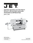
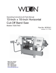
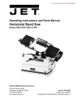
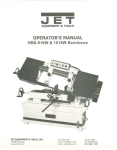
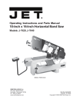
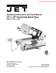
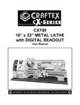
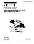
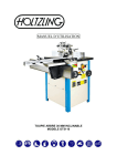
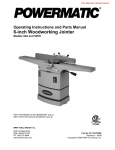
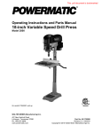
Operating Instructions — Parts Manual
20-Inch x 20-Inch Semi Automatic
Horizontal Cut-Off Band Saw
Model: 7060
WHM TOOL GROUP
2420 Vantage Drive
Elgin, Illinois 60124
Ph.: 800-274-6848
www.wmhtoolgroup.com
Part No. 5511736
Revision A2 08/06
Copyright © WMH Tool Group
Table of Contents
Cover Page ........................................................................................................................... 1
General Specifications .......................................................................................................... 4
Operating Precautions .......................................................................................................... 5
Operating Instructions ........................................................................................................... 7
Blade Selection/Break-in Procedures.................................................................................... 9
Work Set-up ....................................................................................................................... 10
Adjustments .........................................................................................................................11
Maintenance ....................................................................................................................... 14
Wiring Diagram ................................................................................................................... 19
Troubleshooting .................................................................................................................. 20
Replacement Parts ............................................................................................................. 22
3
General
Specifications
The Wilton 7060 Semi-Automatic Horizontal Cut-Off
Band Saw incorporates a number of exclusive design
features and innovations to make this saw a powerful
and productive addition to machine shops, maintenance shops, tool rooms, and fabrication and welding
shops. The exclusive swivel control panel allows the
operator access to all machine controls from any side
of the machine. The exclusive 6-point contact blade
guide assemblies give the machine greater accuracy
and longer blade life. The rapid acting, patented, 3jaw vise provides simple, fast, and accurate set-ups
for both straight and miter cuts. In addition, the semiautomatic cycle enables the operator to initiate, with
the push of a button, the following steps: blade start,
saw head frame down, blade stop, and saw head
frame up. This completely versatile band saw is a
proven time saver, offering optimum sawing performance.
Specifications
4
Cutting Capacity
At 90 degrees
At 45 degrees
12 inches Round/12 x 35 inches Rectangle
12 inches Round/12 x 12 inches Rectangle
Blade Size
Blade Wheel Diameter
Blade Speeds
1 x 0.035 x 156 inches
17 inches Diameter, Cast Iron
82 to 262 SFPM, Variable Speed
Motor
3 HP, 3 Phase, 230/460 Volts
Dimensions
87 x 31.5 x 53 Inches
Net Weight
Shipping Weight
1,144 pounds
1,279 pounds
- Misuse of this machine can cause serious injury.
- For safety, machine must be set up, used and
serviced properly.
- Read, understand and follow instructions in the
Operating Instructions and Parts Manual which
was shipped with your machine.
When Setting up Machine:
- Always avoid using machine in damp or poorly
lighted work areas.
- Always be sure the machine support is securely anchored to the floor or the work bench.
When Using Machine:
- Always wear safety glasses with side shields
(See ANSI Z87.1)
- Never wear loose clothing or jewelry.
- Never overreach - you may slip and fall.
When Servicing Machine:
- Always disconnect the machine from its electrical supply while servicing.
- Always follow instructions in Operating Instructions and Parts Manual when changing accessory tools or parts.
- Never modify the machine without consulting
Wilton Corporation.
You - the Stationary Power Tool User - Hold
the Key to Safety.
Read and follow these simple rules for best results
and full benefits from your machine. Used properly,
Wilton’s machinery is among the best in design and
safety. However, any machine used improperly can
be rendered inefficient and unsafe. It is absolutely
mandatory that those who use our products be
properly trained in how to use them correctly. They
should read and understand the Operating Instructions and Parts Manual as well as all labels affixed to
the machine. Failure in following all of these warnings can cause serious injuries.
Machinery General Safety Warnings
1. Always wear protective eye wear when
operating machinery. Eye wear shall be
impact resistant, protective safety glasses with
side shields which comply with ANSI Z87.1
specifications. Use of eye wear which does
not comply with ANSI Z87.1specifications
could result in severe injury from breakage of
eye protection.
2. Wear proper apparel. No loose clothing or
jewelry which can get caught in moving parts.
Rubber soled footwear is recommended for
best footing.
3. Do not overreach. Failure to maintain proper
working position can cause you to fall into the
machine or cause your clothing to get caught
pulling you into the machine.
4. Keep guards in place and in proper working
order. Do not operate the machine with guards
re
moved.
5. Avoid dangerous working environments. Do
not use stationary machine tools in wet or
damp locations. Keep work areas clean and
well lit.
6. Avoid accidental starts by being sure the start
switch is OFF before plugging in the machine.
7. Never leave the machine running while unattended. Machine shall be shut off whenever it
is not in operation.
8. Disconnect electrical power before servicing.
Whenever changing accessories or general
maintenance is done on the machine, electrical power to the machine must be disconnected before work is done.
9. Maintain all machine tools with care. Follow
all maintenance instructions for lubricating and
the changing of accessories. No attempt shall
be made to modify or have makeshift repairs
done to the machine. This not only voids the
warranty but also renders the machine unsafe.
10. Machinery must be anchored to the floor.
11. Secure work. Use clamps or a vise to hold
work, when practical. It is safer than using
your hands and it frees both hands to operate
the machine.
12. Never brush away chips while the machine is
in operation.
13. Keep work area clean. Cluttered areas invite
accidents.
14. Remove adjusting keys and wrenches before
turning machine on.
15. Use the right tool. Don’t force a tool or attachment to do a job it was not designed for.
16. Use only recommended accessories and
follow manufacturers instructions pertaining to
them.
17. Keep hands in sight and clear of all moving
parts and cutting surfaces.
18. All visitors should be kept at a safe distance
5
from the work area. Make the workshop completely safe by using padlocks, master
switches, or by removing starter keys.
19. Know the tool you are using — its application,
limitations, and potential hazards.
General Electrical Cautions
This saw should be grounded in accordance with
the National Electrical Code and local codes and
ordinances. This work should be done by a qualified
electrician. The saw should be grounded to protect
the user from electrical shock.
Wire Sizes
Conductor Length
0 - 50 Feet
50 - 100 Feet
Over 100 Feet
Caution: For circuits which are far away from the
electrical service box, the wire size must be increased in order to deliver ample voltage to the motor.
To minimize power losses and to prevent motor
overheating and burnout, the use of wire sizes for
branch circuits or electrical extension cords according to the following table is recommended.
AWG (American Wire Gauge) Number
240 Volt Lines
120 Volt Lines
No. 14
No. 14
No. 14
No. 12
No. 12
No. 8
Safety Instructions on Sawing Systems
6
1. Always wear leather gloves when handling saw
blade. The operator shall not wear gloves when
operating the machine.
2. All doors shall be closed, all panels replaced, and
other safety guards in place prior to the machine
being started or operated.
3. Be sure that the blade is not in contact with the
workpiece when the motor is started. The motor
shall be started and you should allow the saw to
come up to full speed before bringing the saw
blade into contact with the workpiece.
4. Keep hands away from the blade area. See
Figure A.
5. Remove any cut off piece carefully while keeping
your hands free of the blade area.
6. Saw must be stopped and electrical supply must
be cut off before any blade replacement or
adjustment of blade support mechanism is done,
or before any attempt is made to change the
drive belts or before any periodic service or
maintenance is performed on the saw.
7. Remove loose items and unnecessary
workpieces from area before starting machine.
A
B
8. Bring adjustable saw guides and guards as close
as possible to the workpiece.
9. Always wear protective eye wear when operating,
servicing, or adjusting machinery. Eyewear shall
be impact resistant, protective safety glasses
with side shields complying with ANSI Z87.1
specifications. Use of eye wear which does not
comply with ANSI Z87.1 specifications could
result in severe injury from breakage of eye
protection. See Figure B.
10. Nonslip footwear and safety shoes are recommended. See Figure C.
11. Wear ear protectors (plugs or muffs) during
extended periods of operation. See Figure D.
12. The workpiece, or part being sawed, must be
securely clamped before the saw blade enters
the workpiece.
13. Remove cut off pieces carefully, keeping hands
away from saw blade.
14. Saw must be stopped and electrical supply cut
off or machine unplugged before reaching into
cutting area.
15. Avoid contact with coolant, especially guarding
your eyes.
C
D
Introduction
Operating Instructions
This manual includes operating and maintenance
instructions for the Wilton 12-inch by 20-inch Cut Off
Band Saw, Model 7060. This manual also includes
parts listings and illustrations of replaceable parts.
Controls
Cut-Off Saw Features
Refer to Figure 1 and 2 for cut-off saw features
Blade Guide Supports
Blade Wheel Cover
Blade
Speed
Control
Control
Panel
The operating controls for the saw are provided in a
control panel on the left side of the machine. The
control panel is mounted on a pivoting tube. The
pivoting tube allows the operator to position the
control panel in a convenient location.
Power-on
Light
Saw Head Up
Saw Head Down
0
1
10
9
2
Start
Switch
8
3
4
7
5
Coolant Sump
Access Panel
Stop
Switch
6
0
Feed Rate
Knob
Blade Guides
Saw
Blade
Coolant
Overflow
Coolant
Temperature
Base
Figure 1: Saw Features (Front View)
Hydraulic
Cylinder
Saw
Head
Blade
Tension
Handwheel
Vise
Handwheel
Drive
Motor
Hydraulic Pump
and Reservoir
Electrical
Panel
Work Table
Coolant
Pump
Access
Panel
Figure 2: Saw Features (Rear View)
Capped Openings
Emergency Stop
(Non-functional)
Coolant Pump Switch
Figure 3: Control panel
The upper row of controls include the following:
1. Power On light indicates when power is connected to the machine.
2. Saw Head Up pushbutton is used to raise the
head.
3. Saw Head Down pushbutton is used to lower the
head onto the workpiece.
The center row of controls include the following:
1. Start pushbutton is used to start the saw blade
drive motor and the hydraulic pump motor. The
hydraulic pump provides the hydraulic pressure
required to raise and lower the saw head.
2. Feed Rate control is used to set the rate at which
the blade feeds through the workpiece.
Variable Speed Adjustment From
25 MPM TO 75 MPM
Recommended Speed for Cutting Various Materials
SPEED/MPM
25
40
50
75
Material To Be Cut
Tool Steel, Stainless Steel, Alloy Steel, Phosphor
Bronze, Hard Bronze, Hard Cast Iron, Malleable Iron.
Mild Steel, Soft Cast Iron, Medium Hard
Brass, Medium Hard Bron
Soft Brasses and Bronzes, Hard Aluminum, Plastics
Plastics, Soft and Medium Soft Aluminum,
Wood, Other Light Materials
7
The bottom row of controls include the following:
1. Stop pushbutton is used to stop the saw blade
drive motor.
2. Emergency stop pushbutton is used to quickly
disconnect electrical power to the machine.
3. Coolant On/Off selector switch is used to start
and stop the coolant pump motor.
Other Controls
Refer to Figures 1 and 2 for location of the following
controls:
1. Drive motor speed control: used to set drive
motor speed in meters per minute.
2. Blade guide support adjustment: used to set
distance between the saw blade guide bearing as
required by the size of the workpiece.
3. Blade tensioning hand wheel: use to tighten the
saw blade on the drive and idler wheels.
4. Vise clamping hand wheel: used to tighten the
vise jaws against the workpiece.
Setting Blade Speed
1. The blade speed is controlled by an adjustment
mechanism on the right end of the saw. Speed
increases when the adjustment knob is turned
counterclockwise. Speed decreases when the
knob is turned clockwise.
2. A placard on the drive belt guard (shown below)
provides recommended speeds for various
materials.
3. A speed indicator is provided on the barrel of the
adjustment mechanism. The indicator provides
speed indications in feet per minute and meters
per minute. (The meters per minute values are
shown in parenthesis on the indicator.) The
graduations are:
8
WARNING: TO CHANGE SPEED, THE SAW
MOTOR MUST BE OPERATING.
5. Turn the speed adjustment knob to the desired
rate setting as determined by the material being
cut.
Raising/Lowering the Saw
Head
1. To raise the saw head, press the Saw Head Up
pushbutton. The saw head will raise until the
upper limit switch (refer to Figure 4) trips.
2. To lower the saw head, press the Saw Head
Down pushbutton. The saw head will lower until
the lower limit switch trips.
3. When the saw head is being lowered to cut a
workpiece, the saw blade drive motor must be
started before lowering the blade against the
workpiece. Set the coolant pump selector to the
on ( I ) position If coolant is required by the
material being cut.
Upper
Limit
Switch
(FT)
12
11
10
9
8
7
Lock
Handle
6
5
4
3
2
1
Scale
0
Hydraulic
Cylinder
Lower
Limit
Switch
Feet per Minute Meters per Minute
70
(21)
100
(30)
130
(40)
160
(48)
Lower
Limit
Stop
Figure 4: Limit Switches
4. The feed rates on the placard are expressed in
meters per minute. The feed rate graduations
available on the indicator may not match the
recommended feed rate. An approximate speed
may therefore be required. For example, to set a
speed rate of 25 meters per minute, the indicator
would be set about midway between 21 metersper-minute and the 30 meters-per-minute graduations.
Controlling the Cut:
Hydraulic Feed Control
The weight of the saw arm provides all the force
needed to move the saw blade through the workpiece.
In fact, if the full weight of the arm is allowed to make
the cut, rapid blade wear and poor cutting accuracy
will result. A hydraulic feed control is provided on the
control panel to provide the operator with a means to
control the speed and efficiency of the cutting operation.
The hydraulic cylinder is attached to the saw base
and the saw head. Hydraulic pressure is provided to
both sides of the hydraulic cylinder piston to raise
and lower the saw head. The feed rate control on the
control panel determines the rate at which the saw
head is raised or lowered.
The amount of downward force can be controlled
by using the feed rate control valve. When the valve
is opened slightly, the saw head will move downward.
The further the valve is opened, the faster the saw
head will move downward.
The feed control is adjusted by the operator to
maintain cutting efficiency. This is usually determined by observing the chip formation. (See Evaluating Blade Efficiency for more information on cutting
efficiency.)
Evaluating Cutting Efficiency
Is the blade cutting efficiently? The best way to
determine this is to observe the chips formed by the
cutting blade.
If the chip formation is powdery, then the feed rate
is much too light, or the blade is dull.
If the chips formed are curled, but colored — that
is, either blue or straw-colored from heat generated
during the cut — then the feed rate is too high.
If the chips are slightly curled and are not colored
by heat — the blade is sufficiently sharp and is
cutting at its most efficient rate.
Blade Selection
The cut-off saw is provided with a saw blade that is
adequate for a variety of cut-off jobs on a variety of
common materials. A 4/6 vari tooth bi-metal blade
(5512107) and a 6/10 vari tooth bi-metal blade
(5512108) are available from Wilton.
See Setting Blade Speed for the speeds recommended for various materials. These selections, while
appropriate for many shop cutting needs, do not
encompass the wide variety of blades of special
configuration (tooth pitch and set) and special alloys
for cutting unusual or exotic materials.
A coarse blade could be used for a solid steel bar
but a finer tooth blade would be used on a thin-wall
tube. In general, the blade choice is determined by
the thickness of the material; the thinner the material,
the finer the tooth pitch.
A minimum of three teeth should be on the work
piece at all times for proper cutting. The blade and
workpiece can be damaged if the teeth are so far
apart that they straddle the workpiece.
For very high production on cutting of special
materials, or to cut hard-to-cut materials such as
stainless steel, tool steel, or titanium, you can ask
your industrial distributor for more specific blade
recommendations. Also, the supplier who provides
the workpiece material should be prepared to provide
you with very specific instructions regarding the best
blade (and coolant or cutting fluid, if needed) for the
material and shape supplied.
Blade Break-in Procedures
New blades are very sharp and, therefore, have a
tooth geometry which is easily damaged if a careful
break-in procedure is not followed. Consult the blade
manufacturer’s literature for break-in of specific
blades on specific materials. However, the following
procedure will be adequate for break-in of Wiltonsupplied blades on lower alloy ferrous materials.
1. Clamp a round section workpiece in the vise. The
workpiece should be 2 inches or larger in diameter.
2. Set the saw on low speed. Start the cut with a
very light feed rate.
3. When the saw has completed 1/3 of the cut,
increase the feed rate slightly and allow the saw
to complete the cut.
4. Keep the same hydraulic cylinder setting and
begin a second cut on the same or similar
workpiece.
5. When the blade has completed about 1/3 of the
cut, increase the feed rate. Watch the chip
formation until cutting is at its most efficient rate
and allow the saw to complete the cut (see
Evaluating Blade Efficiency). The blade is now
considered ready for regular service.
9
Set Workpiece
Against Corner
of Right
Vise Jaw
Angle
Setting
Block
Work Set-up
Securing the Workpiece for
Square Cuts (see figure 5)
1. Raise the saw head.
2. Slide the left vise jaw far enough to the left to allow
the workpiece to be placed in the vise.
3. Place the workpiece on the work table. If the
workpiece is long, provide support at the other
end. It may also be necessary to provide additional downward clamping to hold the workpiece
securely on the work table.
4. Turn clamping hand wheel clockwise to clamp the
workpiece in position against the fixed (right) vise
jaw.
5. After completing the cut, turn the clamping hand
wheel counterclockwise and slide the left jaw away
from the workpiece.
Left
Vise
Jaw
Pivot
Screw
Angle
Locking
Screw
Figure 6: Adjusting vise
Angle Block
Locking Handle
Angle
Pointer
Clamping
Hand
Wheel
Left Vise Jaw
Saw Head
Work Table
Figure 7: Angle setting block
Installation and Adjustment of
Work Stop
The work stop is used to set up the saw for
making multiple cuts of the same length (see figure
8). Install and adjust the work stop as follows:
Figure 5: Securing workpiece
Stop Post
Adjusting the Vise for Angle
Cuts (see figure 6)
10
1. Loosen the angle locking screw and the pivot
screw on the left vise jaw.
2. Turn the locking handle on the round, anglesetting block counterclockwise to unlock the block.
Slide the block until the pointer on the block is
aligned with desired angle (see figure 7). Tighten
the locking handle to set the angle.
3. Set the workpiece in the vise. Put the front end of
the workpiece against the corner of the right vise
jaw. Put the rear end of the workpiece against the
angle-setting block.
4. Turn clamping hand wheel clockwise until the left
vise jaw is parallel with the workpiece. Tighten the
pivot screw and angle locking screw on the left
vise jaw. Clamp the workpiece in position.
5. After completing the cut, turn the clamping hand
wheel counterclockwise and slide the left jaw away
from the workpiece.
Locking Lever
"Wing" Screw
Stop L-Bracket
Knob
Stop Rod
Figure 8: Work stop
1. Insert the end of the stop rod in the hole in the
front right side of the work table.
2. Tighten the “wing” screw to secure the rod in
place.
3. Install the stop post in the channel on the back of
the stop L-bracket. Install the locking lever in the
threaded hole in the stop post. Snug-up the
locking lever.
4. Install the locking knob in the hole in the side of
the stop L-bracket.
5. Slide the assembled stop L-bracket onto the stop
rod. Position the stop post against the work piece
and tighten the knob in the stop L-bracket. The
stop post can be moved left or right as required to
place the stop post against the work piece.
Starting the Saw
WARNING: NEVER OPERATE THE SAW WITHOUT BLADE COVERS IN PLACE AND SECURED.
CAUTION: MAKE SURE THE BLADE IS NOT IN
CONTACT WITH THE WORKPIECE WHEN THE
MOTOR IS STARTED. DO NOT DROP THE SAW
HEAD ON THE WORKPIECE OR FORCE THE SAW
BLADE THROUGH THE WORKPIECE.
1. Raise the saw head.
2. Clamp the workpiece in the vise. (See figure 9 for
examples of workpieces in the vise.)
3. Be sure to start the saw blade drive motor before
allowing the blade to contact the workpiece.
4. Start the motor and allow the saw to come up to
speed.
5. Slowly bring the saw down onto the workpiece.
Adjust feed rate using feed rate control.
6. DO NOT LOWER THE SAW HEAD AT A RATE
FASTER THAN THE SAW’S CAPABILITY OR
FORCE THE CUT. Adjust the feed rate so the
hydraulic cylinder provides the proper amount of
downward force.
7. The saw will automatically shut off at the end of
the cut.
Rounds
Coolant Flow
CAUTION: THE COOLANT PUMP MUST BE SUBMERGED BEFORE OPERATING TO PREVENT
DAMAGE TO THE PUMP.
1. The blade guides are fitted with coolant fittings.
Coolant is provided to the fittings through interconnecting tubing. The coolant is dispensed directly
onto the saw blade.
2. Adjust the coolant flow valves on the top, rear of
the saw head as required to provide the desired
flow. The flow should be no more than the blade
can draw into the workpiece by movement of the
blade.
3. The coolant flow can be stopped in two ways:
1) By using the coolant pump switch on the
electrical equipment box, or
2) By closing the coolant flow valves on the top,
rear of the saw head.
Coolant Mixture and Quantity
The general purpose coolant is a mixture of water
soluble oil and water. Mix one part of soluble oil
(TRIM SOL) to ten parts of water (one quart oil, ten
quarts of water). The eleven quarts of coolant is the
amount required for the coolant pump to operate
properly.
There are numerous coolants on the market that
are formulated for special applications. Consult your
local distributor for details in the event you have a
long range production task, or are required to cut
some of the more exotic materials.
Adjustments
Flats/strips
Channels
Knock off
f
sharp fedge
here with
f
file
Angles
I-Beams
The efficient operation of the cut-off saw is
dependent upon the condition of the saw blade. If the
performance of the saw begins to deteriorate, the first
item that you should check is the blade.
If a new blade does not restore the machine’s
cutting accuracy and quality, refer to the Troubleshooting section (or the blade manufacturer’s guide)
for conditions to consider and adjustments that can
be made to increase the life of the blade.
To change the blade, refer to Changing Blades in
the Maintenance section. To adjust the blade tracking, refer to the following procedures.
Squares/rectangles
f
Knock off
sharp edge
f
here
with
file
Hexagonals
Tees
Figure 9: Placing workpieces in the vise
Blade Tracking Adjustment
Blade tracking has been tested at the factory. Adjustment is rarely required when the blade is used
properly or if the blade is correctly welded. (See
figure 10 for location of blade tracking adjustment
11
Blade Tracking
Hex Adjustment
Screws
Single
Adjustment
Screw
Center
Locking
Screws
Figure 10: Blade tracking and tensioning
screws.)
Factory or Field Procedure
1. Raise the saw head enough to allow the saw motor
to operate.
2. Loosen four knobs securing the blade cover. Lift
the cover and swing it backward.
3. Remove the blade guard mounted on the left blade
guide support.
4. Remove both blade guide bearing brackets.
NOTE: Maintain proper tension at all times using the
blade tensioning mechanism.
5. Loosen the center locking screws in all three hex
adjustment screws on the blade tensioning
mechanism (see figure 10).
CAUTION: WHILE PERFORMING THE FOLLOWING, KEEP THE BLADE FROM RUBBING EXCESSIVELY ON THE SHOULDER OF THE WHEEL.
EXCESSIVE RUBBING WILL DAMAGE THE
WHEEL AND/OR THE BLADE.
12
6. Start the saw. Slowly turn the single hex adjustment screw at the rear of the tracking mechanism
to tilt the idler wheel. Do not turn either of the
other two adjustment screws. Turn the adjustment
screw until the blade is touching the shoulder of
the idler wheel.
NOTE: Turning the screw inward causes the blade to
move toward the shoulder of the wheel. Turning the
screw outward causes the blade to move away from
the shoulder.
7. Turn the single hex adjustment screw so the blade
starts to move away from the shoulder of the
wheel — then immediately turn the single hex
adjustment screw in the other direction so the
blade stops, then moves slowly toward the shoulder.
WARNING: KEEP FINGERS CLEAR OF THE
BLADE AND WHEEL TO AVOID INJURY.
8. Turn the single hex adjustment screw to stop the
motion of the blade on the wheel as it gets closer
to the wheel shoulder. Put a 6-inch length of
paper between the blade and the wheel as shown
in figure 11. The paper should not be cut as it
passes between the wheel shoulder and the blade.
9. Turn the single hex adjustment screw a small
amount. Repeat the insertion of the paper
between the wheel shoulder and the blade until the
paper is cut in two pieces.
NOTE: You may have to repeat the check with the
paper several times before the blade and the shoulder
cuts the paper into two pieces. Do not hurry the
adjustment. Patience and accuracy here will pay off
with better, more accurate, quieter cutting and much
longer machine and blade life.
10. When the paper is cut, turn the hex adjustment
screw slightly in the counterclockwise direction.
This assures that the blade is not touching the
shoulder of the wheel.
11. Shut off the saw.
12. Hold the hex adjustment screws with a wrench
and tighten the center locking screws. Make sure
the hex adjustment screws do not move while
tightening the center screws.
13. Install the two blade guide bearing brackets.
Position the guides so the bearings just touch the
blade.
14. Install the left blade guard.
15. Close the saw head cover. Tighten the four
knobs.
Motor "ON"
Upper Wheel
Rotating
Put Strip
Between
Wheel
and
Blade
Figure 11: Checking blade-to-wheel
clearance using paper strips
Blade Guide Bearing
Adjustment
Proper adjustment of the blade guide bearings is
critical to efficient operation of the cut-off saw. The
blade guide bearings are adjusted at the Factory.
They should rarely require adjustment. When
adjustment is required, adjust immediately. Failure to
maintain proper blade adjustment may cause serious
blade damage or inaccurate cuts.
It is always better to try a new blade when cutting
performance is poor. If performance remains poor
after changing the blade, make the necessary
adjustments.
If a new blade does not correct the problem,
check the blade guides for proper spacing. For most
efficient operation and maximum accuracy, provide
0.001 inch clearance between the blade and the
guide bearings. The bearings will still turn freely with
this clearance. If the clearance is incorrect, the
blade may track off the drive wheel.
CAUTION: CHECK THE BLADE TO MAKE SURE
THE WELDED SECTION IS THE SAME THICKNESS
AS THE REST OF THE BLADE. IF THE BLADE IS
THICKER AT THE WELD, THE GUIDE BEARINGS
MAY BE DAMAGED.
If required, adjust the guide bearings as follows:
1. Two blade guides are used in each set of blade
guides. The inner blade guide is fixed; the outer
blade guide is adjustable. The outer blade guide
is adjusted using a knurled knob on the operator
side of the blade guide assembly.
2. A guide bearing is provided on the innermost
side of the saw blade. The guide bearing is
mounted on an eccentric bushing.
3. Hold the bushing with a 3/4-inch wrench and
loosen the center locking screw with an Allen
wrench (see figure 12).
4. Position the bearing by turning the bushing. Set
the clearance at approximately 0.001 inch.
INCORRECT
Outer
Roller
5. Tighten the center locking screw with an Allen 5.
5. Tighten the center locking screw with an Allen
wrench while holding the eccentric bushing in
position with the 3/4-inch wrench.
6. When the adjustment is correct, the guide
bearing should rotate freely with slight pressure
of the finger (with the blade stopped).
7. Adjust blade-edge bearings so they just touch
the back edge of the blade (see figure 19).
Concentric Bushing
Blade Guide
Bearings
Socket Cap Screw
Eccentric
Bushing
Carbide
Guides
Knurled Knob
Figure 13: Adjustment of Guide Bearing
Test Cutting to Verify
Adjustment Accuracy
1. Clamp in vise and mark top
of barstock here
2. Cut off a slice of
the bar stock
13
3. Rotate stock in vise
so mark is at bottom
4. Cut off a new
slice from the
stock
CORRECT
Inner
Roller
5. Measure
here...
New slice
Locking Screw
Figure 12: Blade-To-Blade Guide Orientation
6. ...measure
here
7. Differences between
measurements at edges
of disc should be less
than .003 inches per
inch per side of stock
diameter
Figure 14: Cutting a Test
Test cuts can be used to determine whether or not you
have adjusted the blade accurately. Use 2-inch round
bar stock to perform these test cuts, as follows:
1. With the bar stock securely clamped in the vise,
make a cut through the bar stock. (See figure 14.)
2. Mark the top of the bar stock.
3. Move the bar stock about 1/4-inch past the blade
so you can begin a second cut.
4. Rotate the bar stock 180 degrees so the mark you
made is now at the bottom of the cut.
5. Make a cut through the bar stock.
6. Use a micrometer to measure the thickness
variation of the disk you have cut from the bar
stock. Measure at the top and bottom of the disk.
The saw blade can be considered correctly adjusted when the variation measure is no more than
0.012 inch across the face of the disk.
Note: If you do not have a piece of 2-inch bar stock
available for a test cut, use a larger diameter test
piece rather than a smaller one. Maximum thickness
variation on any test piece should be no more than
0.003 inch, per side, per inch of stock diameter.
Adjustment of Limit Switches
Adjustment of Lower Limit Switch
1. The lower limit switch is provided to shut off the
saw blade drive motor when the workpiece is cut
through. The switch causes the saw head to raise
to its uppermost stop.
2. To set the limit switch, loosen the jam nut on the
limit switch stop (figure15).
3. Adjust the stop as required and retighten jam nut.
Adjustment of Upper Limit Switch
14
1. The upper limit switch is provided to stop the saw
head when it reaches its uppermost stop.
2. To set the upper limit switch, loosen the clamping
knob on the limit switch support bracket. Move the
limit switch to the desired switch trip point (use the
scale on the side of the support bracket).
Lower Limit Switch
Switch Follower
Lower Limit Stop
Jam Nut
Figure 15: Lower Limit Switch Stop Adjustment
Maintenance
Cleaning
1. Clean off any preservative on machine surfaces.
2. After cleaning, coat the machined surfaces of the
cut-off saw with a medium consistency machine
oil. Repeat the oil coating process at least every
six months.
3. Clean up accumulated saw cuttings after use.
Make sure the lead screw is kept free of saw
cuttings and other material that would cause
damage.
4. Clean the chip sludge from the coolant tank. The
frequency should be determined by how often the
saw is used.
Lubrication
Lubricate the following components at the specified
frequencies and using the lubricants defined below:
1. Ball bearings: the bearings are lubricated and
sealed—periodic lubrication is not required.
2. Blade guide bearing: the bearings are lubricated
and sealed—lubrication is not required. Inspect
periodically.
3. Idler wheel bushing: the bearings are lubricated
and sealed—lubrication is not required. Inspect
periodically.
4. Lead screw bearing housing: lubricate monthly
(see exploded figure, page 20).
5. Lead screw: lubricate with light oil monthly (see
exploded figure, page 20).
6. Hydraulic cylinder pivot: lubricate with light oil
every 6 months (see exploded figure, page 20).
7. Blade tension screw: lubricate with grease every
6 months (see exploded figure, page 24).
8. Blade brush bearing: lubricate with light oil
monthly (see exploded figure, page 24).
9. Gear box: check oil once a year.
10. Change coolant on a frequency appropriate to
the type of coolant being used. Oil based
coolants can sour. Refer to the coolant supplier’s
instructions for change frequency.
11. Coolant tank: clean every 6 months or as required.
12. Hydraulic oil reservoir: check oil level in oil
reservoir by periodically checking the oil level
indicator on the side of the reservoir. If oil level
is low, service reservoir (refer to Servicing
Hydraulic Oil).
Servicing Hydraulic Oil
WARNING: SHUT OFF ALL ELECTRICAL
POWER TO THE MACHINE
1. Remove hydraulic oil reservoir access panel.
2. Check oil level (refer to Figure 16). If level is
below the yellow (upper) line, the reservoir should
be filled.
3. Disconnect electrical power.
4. Remove reservoir fill cap.
5. Add oil until the level is at the yellow (upper) line.
Install reservoir fill cap.
6. If a significant amount of oil needed to be added,
check for oil leaks in pump components, lines,
and hydraulic cylinder. Correct source of
leakage before operating the cut off saw.
7. Connect electrical power. Raise and lower the
saw head to confirm that the saw is operating
correctly.
Motor
FROM THE SAW TEETH.
3. Turn the blade tensioning hand wheel clockwise to
relieve tension on the blade. Loosen the blade
enough to remove the blade from the idler and
drive wheels. Remove the blade from between the
blade guides.
4. Install the new blade between the blade guide
bearings and the carbide blade guides. Install the
blade over the drive and idler wheels.
5. Turn the blade tensioning hand wheel counterclockwise to tighten the blade. Tighten the blade
until the blade tension indicator reads TBD.
6. Operate the saw at low speed and observe the
tracking of the blade. If tracking needs to be
adjusted, refer to Blade Tracking Adjustment.
7. Adjust the bearings on the upper edge of the
blade until they just contact the blade (see figure
19).
8. Check the guide bearings and the carbide guides
to make sure they are just contacting the sides of
the blade.
9. Install the left blade guard making sure there is
ample clearance with the blade.
10. Make a test cut to make sure the blade tracks
properly during operation. Adjust tracking as
required (see Blade Tracking Adjustment).
Pump
Oil Fill Cap
Reservoir
Full Line
(Amber)
Fill Line
(Red, Oil Low)
Figure 16: Checking Hydraulic Oil Level
Changing Blades
WARNING: SHUT OFF ALL ELECTRICAL POWER
TO THE MACHINE.
1. Loosen four knobs securing the blade cover. Lift
the cover and swing it backward.
2. Remove the blade guard mounted to the left blade
guide support.
WARNING: ALWAYS WEAR LEATHER GLOVES
WHEN HANDLING SAW BLADE TO AVOID INJURY
Changing the Drive Belt
1. Disconnect the electrical power source from the
cut-off saw to prevent any possibility of accidental
motor start-up.
2. Set the arm at the full horizontal position.
3. Remove the knob on the drive belt cover. Remove
the drive belt cover to expose the V-belt and
pulleys.
4. Remove two screws, nuts, and washers from back
of saw head support. Push on the motor support
bracket to pivot the motor upward to loosen the
tension on the belt.
5. Remove the worn belt.
6. Put the replacement belt in the pulleys. Allow the
motor to pivot downward.
7. Install the two screws, nuts, and washers in back
of saw head support and through the motor
support bracket.
8. Install the drive belt cover. Install and tighten the
knob on the drive belt cover.
Replacing the Drive Motor
1. Disconnect the motor from all electrical power.
Unplug the motor if it is plugged into a socket.
Shut off the power to the branch and remove the
connection to the junction box if the motor is hard
wired to the branch.
15
2. Remove the drive belt from the drive motor pulley
(see Changing the Drive Belt).
3. Remove motor pulley.
4. Open the motor junction box and disconnect the
power cord wires from their terminals.
5. Remove the nuts, washers and bolts that secure
the motor to the mounting plate.
6. Installation of a new motor is a reversal of the
above steps.
Replacing the Drive Wheel
1. Remove the blade (see Changing Blades).
2. Remove the screw, spring washer, and washer
from the speed reducer shaft.
3. Pull the wheel from the speed reducer shaft.
Remove the drive key from the speed reducer
shaft.
4. Inspection: Examine drive edge and shoulder of
the wheel for damage. Replace the wheel if
damaged.
5. Install the key in the keyway in the speed reducer
shaft. Align the keyway in the wheel with the key
in the speed reducer shaft. Reinstall the wheel on
the speed reducer shaft.
6. Install the screw, spring washer and washer in the
end of the speed reducer shaft.
7. Install the blade (see Changing Blades).
Replacing Idler Wheel or
Idler Bearing
16
1. Remove the saw blade (see Changing Blades).
2. Remove the screw, spring washer, and washer
from the idler shaft.
3. Remove the idler wheel. Remove the bearing from
the idler wheel.
4. Inspection: Examine the drive edge and shoulder
of the idler wheel for damage. Replace the wheel
if damaged.
5. Inspect bearings for damage and smooth operation, Replace if faulty.
6. Install the bearing in the idler wheel. Install the
idler wheel on the idler shaft.
7. Install the screw, spring washer and washer in the
idler shaft.
8. Install the blade (see Changing blades).
Scale (Metric)
Lock
Handle
Lock
Handle
Left
Guide
Support
Right
Guide
Support
Figure 17: Blade Guide Supports
1. Loosen the knob on the blade guide support and
slide the guide left or right as required. Repeat
for the other blade guide.
2. Set the blade guide supports as required to
accommodate the width/diameter of the
workpiece. The blade guides should be positioned so the guides do not contact the workpiece
as the saw head moves downward through the
workpiece.
Blade Tracking
Hex Adjustment
Screws
Single
Adjustment
Screw
Center
Locking
Screws
Figure 18: Blade Guide Features
Replacement of Carbide
Blade Guides (see figure 19)
Coolant Line
Adjusting the Blade Guides
The cut-off saw has adjustable blade guide supports
(see figure 17). The blade guide supports allow you
to set the blade guides for varying widths of
workpieces.
To make accurate cuts and prolong blade life, the
blade guide supports should be set to just clear the
workpiece to be cut.
Scale (Inches)
Guide Support
Chip Brush
Blade Edge
Bearing (2)
Eccentric-Mounted
Guide Bearing
Adjusting Knob
Blade Guides
Figure 19: Carbide Blade Guide Replacement
1. Remove front blade guide by removing adjustment knob, spring, and shaft.
2. Remove the rear blade guide by removing its
attachment screw
3. Install replacement blade guide in the rear guide
location. Secure with attachment screw.
4. Install replacement blade guide in the front guide
location. Install shaft into guide. Install spring
and adjustment knob.
5. Adjust outermost blade guide using adjustment
knob. Set the guide so it just contacts the side of
the blade.
Replacement of Guide
Bearings (see figure 19)
1. Remove the cap screw from the blade guide
bearing. Separate the bushing and cap screw
from the bearing. Discard the bearing.
NOTE: There is a light press fit between the bearing
and the bushing.
2. Install bushing in replacement bearing. Install cap
screw through bushing and into guide support.
3. Turn the eccentric bushing in the guide support
until the bearing contacts the blade.
Replacement of Blade Edge
Bearings (see figure 20)
1. Remove the capscrew from the blade edge
bearing being replaced and discard the bearing.
2. Insert the capscrew into the new bearing.
3. Adjust blade edge guide bearings so they just
contact the edge of the blade.
Adjustment
Cap Screw
Guide Support
Floating Block
2. Remove the attaching screw, spring washer and
washer. Remove and discard the brush (see
figure 20).
3. Install replacement brush and secure with screw,
spring washer and washer.
4. Close the blade cover and secure with four knobs.
Wire Brush
Screw and Washers
Figure 21: Wire Brush
Replacing the Coolant Pump
WARNING: DISCONNECT ELECTRICAL POWER
TO THE MACHINE BEFORE PERFORMING ANY
MAINTENANCE.
1. Disconnect electrical power.
2. Remove four screws and the coolant sump cover
from the machine base (refer to Figure 21).
3. Disconnect coolant pump wiring (refer to Wiring
Data).
4. Remove coolant pump attaching screws. Remove the coolant pump.
5. Install replacement coolant pump and secure with
attaching screws.
6. Connect electrical wiring to coolant pump (see
Wiring Data).
7. Connect electrical power. Start the machine to
check operation of the pump.
8. Install the coolant sump cover and secure with
four screws.
Cap Screw
Access Panel
Screws (4)
Blade Edge
Bearing
Access Panel
Coolant Pump
Junction Box
Figure 20: Blade Edge Bearing Replacement
Pump Screws (2)
Replacement of the Wire
Brush
1. Loosen four knobs securing the blade cover. Lift
the cover and swing it backward.
Coolant
Drain
Figure 22: Replacement of Coolant Pump
17
Machine Setup
The saw delivered to you has been adjusted at the
factory. A number of test pieces have been cut using
the saw to verify the accuracy of cutting. Therefore,
the only setup operations required before releasing
the saw for service are spotting the saw and establishing the electrical connections to the motor.
Uncrating and Spotting
Spot the saw where it makes the most sense for the
operations you will probably be doing. If you are
going to be doing cut-off work on very long pieces of
stock, allow plenty of room for the stock, and the
infeed and outfeed supports. Remove the saw from
the shipping skid and discard any hold-down devices
that were used to secure the saw to the skid.
Electrical
Observe the following when connecting to the power
source. (The cut-off saw wiring diagrams are
provided in Figures 21 and 22.)
WARNING: WILTON RECOMMENDS THAT ANY
WIRING INVOLVING HARD WIRING OF THE SAW
TO A BRANCH, OR ANY CHANGE OF VOLTAGE
SUPPLIED TO THE MOTOR BE PERFORMED BY A
LICENSED ELECTRICIAN.
18
1. Make sure the saw is disconnected from the
power source, or that the fuses have been
removed or breakers tripped in the circuit in
which the saw will be connected. Make sure you
put a warning placard on the fuse or circuit
breaker to prevent accidental electrical shock.
2. If you are installing the motor power cord into a
receptacle, make sure to use the appropriate
plug.
3. If you are using hard-wired connections to a
junction box, connect the wires in the box, and
close the box.
4. Install the fuses or reset the breaker.
5. The saw is now ready for service.
Wiring Diagram
19
Troubleshooting
Fault
Probable cause
Suggested remedy
Excessive blade
breakage
1. Material loose in vise.
2. Incorrect speed or feed.
1. Clamp work securely.
2. Check Machinist’s Handbook for
speed/feed appropriate for the
material being cut.
3. Check Machinist’s Handbook for
recommended blade type.
4. Adjust blade tension to the point
where the blade just does not slip
on the wheel.
5. Start the motor before placing the
saw on the workpiece.
3. Teeth too coarse for material.
4. Incorrect blade tension.
5. Saw blade is in contact with
workpiece before the saw is
started.
6. Blade rubs on the wheel flange.
7. Misaligned guides.
8. Cracking at weld.
Premature blade
dulling
1.
2.
3.
4.
Blade teeth too coarse.
Blade speed too high.
Inadequate feed pressure.
Hard spots in workpiece or scale
on/in workpiece.
5. Work hardening of material
(especially stainless steel).
6. Insufficient blade tension.
7. Operating saw without pressure
on workpiece.
6. Adjust blade tracking.
7. Adjust guides.
8. Longer annealing cycle.
1.
2.
3.
4.
Use a finer tooth blade.
Try a lower blade speed.
Decrease spring tension.
Increase feed pressure (hard
spots). Reduce speed, increase
feed pressure (scale).
5. Increase feed pressure by
reducing spring tension.
6. Increase tension to proper level.
7. Do not run blade at idle in/on
material.
Bad cuts
(out-of-square)
1. Workpiece not square with blade. 1. Adjust vise so it is square with the
blade. (Always clamp work tightly
in vise.)
2. Decrease pressure.
2. Feed pressure too fast.
3. Adjust guide bearing clearance to
3. Guide bearings not adjusted
0.001 inch (0.002 inch maximum).
properly.
4. Gradually increase blade tension.
4. Inadequate blade tension.
5. Move blade guide bar closer to
5. Span between the two blade
work.
guides too wide.
6. Replace blade.
6. Dull blade.
7. Check blade speed
7. Incorrect blade speed.
(see Figure 3).
8. Tighten blade guide assembly.
8. Blade guide assembly is loose.
9. Tighten blade guide bearing
9. Blade guide bearing assembly
assembly.
loose.
10. Adjust blade tracking.
10. Blade track too far away from
wheel flanges.
11. Replace worn bearing.
11. Guide bearing worn.
Bad cuts (rough)
1. Blade speed too high for feed
pressure.
2. Blade is too coarse.
20
1. Reduce blade speed and feed
pressure.
2. Replace with finer blade.
Troubleshooting (Continued)
Blade is twisting
1. Blade is binding in the cut.
2. Blade tension too high.
1. Decrease feed pressure.
2. Decrease tension on blade
Unusual wear on
side/back of blade
1. Blade guides worn
2. Blade guide bearings not
adjusted.
3. Blade guide bearing bracket is
loose.
1. Replace blade guides.
2. Adjust blade guide bearings.
1. Blade tooth pitch too coarse for
workpiece.
2. Feed too slow; feed too fast.
1. Use blade with finer tooth pitch.
Teeth missing/ripped
from blade
3. Workpiece vibrating.
4. Gullets loading up with chips.
Motor running too hot
3. Tighten blade guide bearing
bracket.
2. Increase feed pressure and/or
blade speed.
3. Clamp workpiece securely.
4a. Use blade with a coarse tooth
pitch—reduce feed pressure.
4b. Brush blade to remove chips.
1. Blade tension too high.
2. Drive belt tension too high.
3. Blade too coarse for workpiece
(especially with tubular stock).
4. Blade too fine for workpiece
(especially with heavier, soft
material).
5. Speed reducer gears require
lubrication.
1. Reduce tension on blade.
2. Reduce tension on drive belt.
3. Use blade with fine tooth pitch.
No coolant flow
1.
2.
3.
4.
1.
2.
3.
4.
Excessive speed
reducer noise/
vibration
1. V-belt is too tight.
Pump motor is burned out.
Screen/filter on pump is clogged.
Impeller is loose.
Coolant level too low.
4. Use blade with coarse tooth pitch.
5. Check speed reducer.
Replace pump.
Clean screen/filter.
Tighten impeller.
Add coolant to reservoir.
1. Reset V-belt tension.
21
Replacement Parts
This section provides exploded view illustrations that show the replacement parts for the Model 7060 12-Inch x
20-Inch Semi-Automatic Horizontal Cut-Off Band Saw. Also provided are parts listings that provide part number
and description. The item numbers shown on the illustration relate to the item number in the facing parts listing.
Order replacement parts from:
WHM TOOL GROUP
2420 Vantage Drive
Elgin, Illinois 60124
Ph.: 800-274-6848
Identify the replacement part by the part number shown in the parts listing. Be sure to include the model
number and serial number of your machine when ordering replacement parts to assure that you will receive the
correct part.
22
Exploded View – Saw Base - Model 7060 Semi-Automatic Cut-Off Band Saw
11
10
9
8
12
13
1
2
14
15
27
16
17
18
7
21
6
65
66
3
5
20
19
26
29
23
77
48
110
109
117 116
67
68
82
87
88
89
90
91
84
85
86
107
131
121
123
124
106
105
125
104
99
101
100
96
98
95
92
97
94
126
103 102
43
83
70 69
132
128
127
41
71
111
119
120
60
44
73
72
93
58
59
40 61
46
45
81
108
118
129
54
62
80
76
114 115
122
53
63 64
47
113
112
130
38
34
24
75
74
133
37
22
25
134
30
36
55 56 57
79
78
136
135
31 32 51
33 50
49
39
4
137
35
52
28
42
23
24
Parts List – Saw Base - Model 7060 Semi-Automatic Cut-Off Band Saw
Ref
No.
1
2
3
4
5
6
7
8
9
10
11
12
13
14
15
16
17
18
19
20
21
22
23
24
25
26
29
Part
Number
5512120
5512121
5512122
5512123
5512124
5512125
5512126
5512127
5512128
5512129
5512130
5512131
5512121
5512128
5512173
5512131
5512121
5512128
5512174
5512132
5512133
5512134
5512135
5512136
5512137
5512138
5512139
30
27
28
31
32
33
34
5512140
5512141
5512142
5512143
5512144
5512145
5512146
35
36
37
38
39
40
41
42
5512147
5512148
5512149
5512150
5512151
5512152
5512153
5512154
Description
Bolt, Hex Cap (M12X35)
Washer, Lock (M12)
Pin
Rack
Bracket, Slide
Block, Rack
Screw, Set (M6X10)
Jaw, Vise (Left)
Washer (M12)
Washer, Lock (M12)
Bolt, Locking (M12X35)
Bolt, Hex Cap (M12X40)
Washer, Lock (M12)
Washer (M12)
Jaw, Vise (Right)
Bolt, Hex Cap (M12X40)
Washer, Lock (M12)
Washer (M12)
Scale, Angle
Block, Protractor Vise
Handle, Locking
Washer (1/2-inch)
Screw (3/8 x 1-inch)
Washer
Seat, Protractor
Stop Block, Protractor
Screw, Hex Cap, Socket
(M10X25)
Washer (M10)
Bolt, Hex Cap (M8X30)
Nut (M8)
Bracket, Adjusting
Plate, Switch Mounting
Switch Limit (5101)
Screw, Hex Cap, Socket
(M8X20)
Pin, Cylinder
Pin, Retaining
Washer, Lock (M10)
Bolt, Hex Cap (M10X30)
Cover, Cylinder
Pin (20MM)
Shaft, Pivot
Bearing, Needle (CB3020)
Qty
1
1
2
1
1
1
1
1
1
1
1
2
1
1
1
2
1
1
1
1
1
1
3
3
1
1
1
1
1
1
1
1
1
4
1
1
4
4
1
1
1
1
Ref
No.
43
44
45
46
47
48
49
50
51
Part
Number
5512155
5512156
5512140
5512150
5512157
5512158
5512159
5512160
5512161
52
5512162
53
54
5512163
5512146
55
56
57
58
59
60
61
62
63
5512128
5512164
5512165
5512166
5512167
5512168
5512169
5512156
5512171
64
65
66
67
68
69
70
71
72
5512167
5512676
5512677
5512175
5512154
5512128
5512155
5512178
5512179
73
74
75
76
77
78
79
80
5512167
5512166
5512182
5512183
5512213
5512156
5512184
5512185
Description
Bolt, Hex Cap (M8X25)
Washer, Lock (M8)
Washer (M10)
Bolt, Hex Cap (M10X30)
Spring
Cylinder Assembly,Hydraulic
Plate, Switch Stop
Washer, Lock (M6)
Screw, Hex Cap, Socket
(M6X12)
Plate, Hydraulic Mounting
(Top)
Switch Limit (5102)
Screw, Hex Cap, Socket
(M8X20)
Washer (M12)
Washer, Lock (M12)
Bolt, Hex Cap (M8X50)
Bolt, Hex Cap (M8X20)
Washer (M8)
Bracket, Pivot
Bracket, Limit Switch
Washer, Lock (M8)
Bolt, Hex Cap, Socket
(M8X20)
Washer (M8)
Hand Wheel Assembly
Seat, Lead Screw
Work Table
Bearing, Needle (CB3020)
Washer (M12)
Bolt, Hex Cap (M8X25)
Knob, Lock
Bolt, Hex Cap, Socket
(M8X25)
Washer (M8)
Bolt, Hex Cap (M8X20)
Seat, Lead Screw
Screw, Lead
Washer (M8)
Washer, Lock (M8)
Bolt, Hex Cap (M8X30)
Screw
Qty
1
1
1
1
1
1
1
1
1
1
1
4
3
3
3
4
4
1
1
2
2
2
1
1
1
1
1
2
1
1
1
2
1
1
2
2
2
4
Ref
No.
81
82
83
Part
Number
5512186
5512187
5512188
84
85
86
87
88
89
90
91
92
93
5512189
5512190
5512191
5512126
5512192
5512164
5512128
5512194
5512195
5512188
94
95
96
97
98
99
100
101
102
103
104
105
106
107
5512197
5512198
5512199
5512200
5512201
5512140
5512202
5512203
5512204
5512205
5512206
5512207
5512208
5512188
108
109
110
111
112
113
114
115
116
117
118
119
5512210
5512211
5512212
5512675
5512214
5512215
5512216
5512217
5512218
5512219
5512220
5512221
Description
Cover, Electrical Panel
Valve, Solenoid
Screw, Hex Cap, Socket
(M6X8)
Cover, Panel
Pump Assembly, Hydraulic
Motor
Screw, Set (M6X10)
Bolt, Hex Cap (M12X35)
Washer, Lock (M12)
Washer (M12)
Seat, Hydraulic
Cover, Panel
Screw, Hex Cap, Socket
(M6X8)
Plug, Drain (3/8-In. PT)
Nut, Hex (M12)
Bolt, Hex Cap (12X70)
Bolt, Hex Cap (M10X30)
Gauge, Coolant
Washer (M10)
Nut (M10)
Base
Knob, Lock
Bracket, Stop
Handle, Lock
Stop, Work
Rod, Stop
Bolt, Hex Socket Cap
(M6X8)
Cover, Panel
Washer, Lock
Screw, Pan Head (M6X16)
Pump, Coolant (1-Hp/3Ph)
Tube, Connecting
Switch (Saw Head Up)
Switch (Saw Head Down)
Screw, Pan Head (M5X8)
Panel, Control
Control, Cutting Pressure
Box, Control
Handle
Qty
1
1
4
1
1
1
1
2
2
2
1
1
4
1
4
4
2
1
2
2
1
1
1
1
1
1
4
1
2
2
1
1
1
1
8
1
1
1
1
Parts List – Saw Base - Model 7060 Semi-Automatic Cut-Off Band Saw, (Continued)
Ref
No.
120
121
122
123
124
125
126
127
128
129
130
131
132
133
134
135
136
137
138
139
140
142
141
143
144
145
Part
Number
5512222
5512223
5512224
5512225
5512226
5512227
5512228
5512229
5512230
5512231
5512232
5512228
5512234
5512235
5512682
5512237
5512238
5512681
5512240
5512241
5512242
5512243
5512244
5512245
5512246
5512247
Description
Screw, Pan Head (M6X15)
Valve, Relief
Plate, Cover
Box, Stationary
Screw (M8X16)
Plate, Sole
Screw (1/4X5/8 In.)
Bushing, Stationary Box
Collar
Screw (M5X8)
Rod, Control
Screw (1/4X5/8 In.)
Bushing, Control Box
Switch, Coolant
Emergency Stop
Switch, Stop
Switch, Start
Light, Power Indicator
Strip, Terminal
Transformer (3Ph)
Fuse 1A
Fuse 2A
Fuse 3A
Relay
Switch, Overload
Contactor, Magnetic (3Ph)
Qty
4
1
1
1
4
1
2
1
1
4
1
2
1
1
1
1
1
1
1
1
1
2
1
2
1
3
138
145
2A 3A 1A
139
143
142
140
141
144
Electrical Components
25
26
Exploded View – Saw Head - Model 7060 Semi-Automatic Cut-Off Band Saw
146
147
148
149
167
171
150
166
163
164
168
158
165
152
162
161
156
159
169
153
154
155
201
230
157
200
199
173
205
203
228
198
206
204
227
174
197
196
207
195
175
226
231
225
209
208
222
224
232
220
218
236
235
244
190
211
185
184
183
182
181
193
213
See Detail 'A'
248
259
246
249
258
251
252
257
256
255
247
253
254
178
192
214
239
240
241
243
212
177
191
215
238
245
194
217
216
237
219
210
221
176
186
223
260
234
170
202
229
160
233
172
151
239
Detail 'A'
180
179
Parts List – Saw Head - Model 7060 Semi-Automatic Cut-Off Band Saw
Ref
No.
146
147
148
149
150
151
152
153
154
155
156
Part
Number
5512248
5512249
5512250
5512251
5512252
5512253
5512254
5512255
5512126
5512256
5512257
157
158
159
160
161
5512128
5512259
5512260
5512261
5512146
162
163
164
165
166
167
168
169
170
171
172
173
174
175
176
177
178
179
180
181
182
183
184
185
186
5512156
5512263
5512264
5512265
5512266
5512267
5512268
5512269
5512270
5512271
5512272
5512273
5512274
5512156
5512275
5512276
5512277
5512278
5512279
5512280
5512281
5512282
5512283
5512284
5512167
Description
Bearing, Thrust (51194NJK)
Indicator, Tension
Washer, Flat
Washer, Special Spring
Bracket, Slide
Washer, Lock
Screw, Hex Cap
Screw Assembly
Screw, Set (M6X10)
Nut, Hex (M16)
Screw, Hex Cap, Socket
(M12X25)
Washer (M12)
Bracket, Slide
Gib
Shaft, Blade Wheel Bracket
Screw, Hex Cap, Socket
(M8X20)
Washer, Lock (M8)
Shaft, Tension
Bar, Extension
Key (5X5X20)
Wheel, Handle
Screw, Set (M8X10)
Head, Connection
Clamp, Hose
Gear Box Assembly
Motor
Key (8X8X40)
Key (7X7X45)
Seat, Support Bracket
Washer, Lock (M8)
Belt (1922V321)
Bolt, Hex Cap (M8X16)
Variable Speed Assembly
Knob (3/8 In.)
Washer
Cover, Pulley
Pulley, Gear Box
Shaft
Plate, Variable Speed
Plate
Washer (M8)
Qty
1
1
1
18
1
3
3
3
1
1
1
1
1
2
1
6
6
1
1
1
1
1
1
5
1
1
1
1
1
3
1
3
1
1
1
1
1
1
1
2
3
Ref
No.
190
191
192
193
194
195
196
197
198
199
200
201
202
203
204
205
206
207
208
209
210
211
212
213
214
Part
Number
5512285
5512149
5512287
5512288
5512192
5512129
5512291
5512292
5512293
5512294
5512295
5512296
5512297
5512128
5512299
5512300
5512301
5512302
5512167
5512156
5512304
5512680
5512306
5512107
5512108
5512308
215
216
217
218
219
220
221
5512149
5512140
5512311
5512312
5512192
5512314
5512315
222
5512316
223
224
225
226
227
228
5512317
5512318
5512319
5512140
5512321
5512322
Description
Box Assembly, Blade Wheel
Washer, Lock (M10)
Bolt, Hex Cap (M10X35)
Hose (30MM)
Bolt, Hex Cap (M12X35)
Washer, Lock (M12)
Nozzle, Flexible
Guide, Blade
Knob
Bolt, Stand
Nut, Hex (1/4 In.)
Clamp, Hose
Bracket, Blade (Left)
Washer (M12)
Bolt, Hex Cap (M12X30)
Bolt, Hex Cap (M6X12)
Washer, Lock (M6)
Bracket, Blade (Right)
Washer (M8)
Washer, Lock (M8)
Seat, Wire Brush
Brush, Wire
Washer (M6)
Blade 4/6 TPI (Standard)
Blade 6/10 TPI
Screw, Hex Cap, Socket
(M10X45)
Washer, Lock (M10)
Washer (M10)
Washer
Screw
Bolt, Hex Cap (M12X35)
Screw, Set (M8X10)
Bracket, Adjustable Mount
(Right)
Bracket, Adjustable Mount
(Left)
Block, Lock
Screw, Set (M8X16)
Handle, Locking (3/8X2 In.
Washer (M10)
Scale, Angle
Screw, Pan Head (M5X8)
Qty
1
4
4
1
4
4
1
1
2
1
1
2
1
4
4
2
2
1
6
6
1
1
1
1
1
4
4
4
1
1
2
4
1
1
2
8
2
2
1
4
Ref
No.
229
Part
Number
5512323
230
231
232
233
234
235
236
237
5512324
5512325
5512326
5512327
5512328
5512329
5512330
5512331
238
239
5512332
5512333
240
241
242
242A
242B
242C
243
244
245
246
247
248
249
250
251
252
253
254
255
5512684
5512683
5512678
5512337
5513861
5517141
5512340
5512341
5512342
5512343
5512344
5512345
5512346
5517140
5512686
5512685
5512350
5512222
5512351
256
257
258
259
260
261
5512160
5512306
5512221
5512354
5512355
5517143
Description
Screw, Hex Cap, Socket
(M10X25)
Bracket, Side
Wheel, Idler
Bearing, Ball (6206Z)
Washer (M12X35W)
Bolt, Hex Cap (M12X25)
Guard, Blade
Bracket, Guide (Left)
Screw, Hex Cap, Socket
(M8X30)
Bearing, Ball
Screw, Hex Cap, Socket
(M6X16)
Rear Blade Guide, Left
Front Blade Guide, Left
Assembly, Eccentric Shaft
Screw, Cap (M8X40)
Bearing, Ball (6201ZZ)
Bushing, Eccentric Shaft
Shaft
Spring
Knob, Adjusting
Wheel, Drive
Washer (M12 X50MM)
Screw
Bracket, Guide (Right)
Bushing, Center Shaft
Rear Blade Guide, Right
Front Blade Guide, Right
Cover, Blade Wheel (Right)
Screw, Pan Head (M6X15)
Screw, Hex Cap, Socket
(M6X12)
Washer, Lock (M6)
Washer (M6)
Handle
Guard, Wire Brush
Screw (1/4X3/8)
Assembly, Center Shaft
Qty
2
1
1
3
1
4
1
1
1
4
4
1
1
2
4
8
2
2
2
2
1
1
1
1
2
1
1
1
4
2
2
2
2
1
6
2
27
WHM TOOL GROUP
2420 Vantage Drive
Elgin, Illinois 60124
Ph.: 800-274-6848