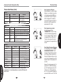
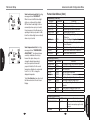
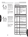
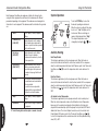
1
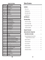
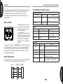
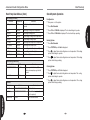
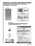
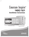
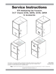
Dealer Installation
and Start-Up Instructions
500 Series Thermostat
Featuring Serial Communication
(-)HC-TST501CMMS
Manual 37-6943A
0830
FAILURE TO READ AND FOLLOW ALL INSTRUCTIONS CAREFULLY
BEFORE INSTALLING OR OPERATING THIS CONTROL AND SYSTEM
COULD CAUSE PERSONAL INJURY AND/OR PROPERTY DAMAGE.
Introduction to Thermostat and Communicating
System
The system consists of a premium indoor furnace or air handler, an outdoor AC
condensing unit or heat pump and touchscreen thermostat that is the HVAC command
center. All these devices are linked together and communicate using ClimateTalk
language protocol. The benefits of ClimateTalk are auto-configuration of the system,
the ability to share information throughout the system for enhanced diagnostics and
control, and straightforward wiring since communications requires attaching only four
wires. This ensures simple, reliable operation and an accurate installation.
System Fault Codes (Cont.)
Display code
81
82
83
84
93
P
d1
d3
d4
d5
d6
d7
d8
Diagnostic Description
Return air sensor out of range
Supply air sensor out of range
Coil Temperature Sensor Fault
Outdoor Ambient Temperature Sensor Fault
Board Failure
Compressor Protector Fault
No Shared Data
Insufficient Indoor CFM
Memory Card Invalid
Card Hardware Conflict
Blower Horsepower Conflict
Blower Manufacturer Conflict
Old Shared Data
WARNING
Thermostat installation and all components of the control system
shall conform to Class II circuits per the NEC code.
WARNING
To prevent electrical shock and/or equipment damage, disconnect
electric power to system at main fuse or circuit breaker box until
installation is complete.
ATTENTION: MERCURY NOTICE
This product does not contain mercury. However, this product may replace a product
that contains mercury.
Mercury and products containing mercury must not be discarded in household
trash. Do not touch any spilled mercury. Wearing non-absorbent gloves clean up any
spilled mercury and place in a sealed container. For proper disposal of a product
containing mercury or a sealed container of spilled mercury, place it in a suitable
shipping container.
Refer to www.white-rodgers.com for location to send the product containing mercury.
Please refer to equipment instructions for additional fault information.
System Fault Codes
Display code
1
2
3
4 (L4)
5 (L5)
6 (L6)
7 (L7)
9
11
12
13
14
21 (L21)
22
23
26
27
28
29 (L29)
30
33
44
45
46
55
57
60
61
66
68
77
78
79
80
Table of Contents
Diagnostic Description
Long Run Time
System Pressure Trip
Short Cycling
Locked Rotor
Open Circuit
Open Start Circuit
Open Run Circuit
Low Secondary Voltage
Failed ignition
Low flame sense current
Flame lost after established
Flame present with gas valve off
Low Pressure Switch Trip
Main limit switch open.
Auxiliary limit switch open
Line Neutral Reversed
Check Line Voltage
High Line Voltage
High Pressure Switch Trip
Fuse Open
MRLC Open
Low pressure switch closed, inducer off
Low pressure switch open, inducer on high speed
Low pressure switch open, inducer on low speed
High pressure switch closed, inducer off
High pressure switch open, inducer on high speed
Blower Fault Run
Blower Fault No Run
RPM out of range (over 1200 RPM)
No Blower Communication
Servo circuit open
Servo control fault
No Gas Valve Feedback
Low Airflow
Installation . . . . . . . . . . . . . . . . . . . . . . . . . . . . . . . . . . . . . . . . . . . . .
4
Battery Location . . . . . . . . . . . . . . . . . . . . . . . . . . . . . . . . . . . . . . . . . . 4
Wiring Requirements . . . . . . . . . . . . . . . . . . . . . . . . . . . . . . . . . . . . . . 4
Quick Installation Steps . . . . . . . . . . . . . . . . . . . . . . . . . . . . . . . . . . . . 5
Installing Thermostat . . . . . . . . . . . . . . . . . . . . . . . . . . . . . . . . . . . . . . 5
Initial Power Up. . . . . . . . . . . . . . . . . . . . . . . . . . . . . . . . . . . . . . . .
6
Thermostat Setup . . . . . . . . . . . . . . . . . . . . . . . . . . . . . . . . . . . . .
8
Set Current Time and Day . . . . . . . . . . . . . . . . . . . . . . . . . . . . . . . . . . 8
Choose the System Setting . . . . . . . . . . . . . . . . . . . . . . . . . . . . . . . . . 9
Energy Saving Factory Program . . . . . . . . . . . . . . . . . . . . . . . . . . . . . 9
Set Up Thermostat Options . . . . . . . . . . . . . . . . . . . . . . . . . . . . . . . . . 10
Using the Thermostat . . . . . . . . . . . . . . . . . . . . . . . . . . . . . . . . . 15
Advanced Installer Configuration
Menu/Service Information . . . . . . . . . . . . . . . . . . . . . . . . 19
Entering and Navigating the Advanced Installer
Configuration Menu/Service Information . . . . . . . . . . . . . . . . . . . . 19
Equipment User Menus . . . . . . . . . . . . . . . . . . . . . . . . . . . . . . . . . . . . 20
Thermostat User Menus . . . . . . . . . . . . . . . . . . . . . . . . . . . . . . . . . . . 23
Furnace User Menus . . . . . . . . . . . . . . . . . . . . . . . . . . . . . . . . . . . . . . 24
Air Handler User Menus. . . . . . . . . . . . . . . . . . . . . . . . . . . . . . . . . . . . 27
Heat Pump User Menus. . . . . . . . . . . . . . . . . . . . . . . . . . . . . . . . . . . . 29
Air Conditioner User Menus. . . . . . . . . . . . . . . . . . . . . . . . . . . . . . . . . 32
Installation
Advanced Installer Configuration Menu
This document provides information for installation of the touchscreen thermostat
only. Installation instructions of the furnace or air handler and outdoor AC
condensing unit or heat pump are provided with each of these devices.
2
This thermostat is designed exclusively for this Comfort Control System
equipment ONLY.
TM
Battery Location
2 "AA" Batteries
2 “AA” alkaline batteries are included
in the thermostat to keep time during a
power outage. They are also required
for armchair programming.
If “LOW BATTERY” is displayed in the
scrolling area, the batteries are low and
should be replaced with fresh batteries.
For best results use premium brand
alkaline batteries, such as Duracell® or
Energizer®.
To replace batteries, set thermostat SYSTEM touch key to Off, remove thermostat
from wall by grasping the top and bottom of the thermostat and pulling straight
away from the wall. The base will remain on the wall. Install the batteries in the
rear along the top of the thermostat. Reposition the thermostat over the base
plate and gently snap into place.
Wiring Requirements
Each communicating device in the system has a four wire connection labelled (R,
C, 1, 2). Each R, C, 1, and 2 terminals must be wired consistently.
Indoor
Board Terminal
Connections
Touchscreen
Thermostat
R
C
1
2
24VAC (Hot)
24VAC
(Common)
Data 1
Data 2
Outdoor
Board Terminal
Connections
R
R
C
C
1
1
2
2
Air Conditioner User Menus (Cont.)
Fault History (FAULT HIST)
Fault Code
Fault Occurred
XXXXXXXXXXXXXXX
Days XX
Clear Faults
No, Yes
Unit Info
Parameter
Comments
Displays up to 6 faults; Days (XX)
indicates how many days ago the fault
occurred
Indications
Comments
Model Number
XXXX-XXXXXXXXXXXXXXXX Unit Model Number
Serial Number
XXXXXXXXXXXXXXXXXXX
Unit Serial Number (not available
if control is replaced)
Software Vers
XXXXXX
Control Software Version
Cool Setup
Parameters
Options
AC Profile
A, B, C, D
Cool Air Adj %
-10, 0, 10
Comments
Selectable Airflow Profiles (See AC Installer
Guide)
Selectable Cooling Airflow Adjustments
On Demand Dehum On, Off
Select Blower Operation based on humidity
Reset All Dflts
Resets the AC to the Factory Default
configuration by selecting Yes
No, Yes
Outdoor Temp Sens On, Off
If Outdoor Ambient Temperature Sensor is Field
installed, turn On. Factory Default is Off
Advanced Installer Configuration Menu
Installation
Quick Install Steps
Air Conditioner User Menus
Comp Hi Pres SW Closed, Open
AC High Pressure Switch Status
Comp Lo Pres SW Closed, Open
AC Low Pressure Switch Status
•
•
•
•
•
•
Outdr Temp Sens
(if enabled)
Outdoor Ambient Temperature Display
(if installed and enabled in setup)
This option will not appear unless the sensor
is enabled
•
•
Set the time
•
•
•
Perform thermostat/system operation checkout.
Status
Parameter
Option
Comments
Compressor
Off, On
Mode
AC, AC1, AC2, Time System Mode of Operation
Delay, Off
XXXF, FLT
2 Week History (2 WK HIST)
Parameter
Indications
Compressor Status
Comments
2wk Y1 Hrs
XXX
2 Week First Stage Cooling Hours of Operation
2wk Y1 Cycles
XXXX
2 Week First Stage Cooling Cycles
2wk Y2 Hrs
XXX
2 Week Second Stage Cooling Hours Operation
2wk Y2 Cycles
XXXX
2 Week Second Stage Cooling Cycles
Life History (LIFE HIST)
Parameter
Indications
Comments
Total Days Pwrd
XXXX
Total number of days control has been
powered
Y1 Hrs
XXXXXX
First Stage Cooling Hours of Operation
Y1 Cycles
XXXXXX
First Stage Cooling Cycles
Y2 Hrs
XXXXXX
Second Stage Cooling Hours of Operation
Y2 Cycles
XXXXXX
Second Stage Cooling Cycles
Determine location of thermostat installation.
Mount thermostat base to wall.
Connect wires to thermostat base.
Remove battery tag to provide battery power to the thermostat.
Attach thermostat to base.
Turn on power to system. Allow approximately 1 minute for the system to
configure.
Select thermostat operating options in the Thermostat Options Configuration
Menu.
Program thermostat or accept factory programming.
Touch Run Schedule.
Installing thermostat
•
Pull the thermostat body off the thermostat base. Forcing or prying thermostat
will cause damage to the unit.
•
Place base at installation location and mark mounting hole locations on wall
using base as a template.
•
•
Move base out of the way. Drill mounting holes.
•
•
Connect wires to terminal block on base.
•
•
Remove battery tag to provide battery power to thermostat.
Attach base snugly to wall using two mounting screws. Levelling is for
appearance only and will not affect thermostat operation.
Push excess wire into wall and plug hole with a fire resistant material (such as
fiberglass insulation) to prevent drafts from affecting thermostat operation.
Carefully line the thermostat up with the base and snap into place.
Initial Power-Up
Advanced Installer Configuration Menu
Power Up
Heat Pump User Menus (Cont.)
Turn on AC power to the system. The thermostat will automatically identify the
communicating components installed.
Cool Setup
Parameter
AC Profile
Messages at Thermostat
During power up, the thermostat will
scroll the word “SEARCHING” in
the message area, indicating that the
system is looking for components
(Air Handler, Furnace, Heat Pump,
Air Conditioner) on the Climate Talk
network. Once the components are
identified the message display will
indicate the components found.
Confirmation will be given in the
message area that the equipment
has been found with the message
(equipment) FOUND.
Note: If the thermostat display continuously shows “SEARCHING”, check the
wiring to the thermostat.
Communications Systems
The thermostat will recognize the
system devices that are connected and
the capacities to set the system up to
the operating settings. The system has
additional flexibility which allows for the
customization of certain parameters.
Options
A, B, C, D
Comments
Selectable Airflow Profiles (see Heat Pump
Installer Guide)
Cool Air Adj %
-10, 0, 10
Selectable Cooling Airflow Adjustments
On Demand
Dehum
On, Off
Select Blower Operation on based on
humidity
Reset All Dflts
No, Yes
Resets the Heat Pump to the Factory
Default Configuration by selecting Yes
Heat Setup
Parameter
Options
Comments
HP Profile
A, B, C, D,
Selectable Airflow Profiles (See Heat Pump
Installer Guide)
Heat Air Adj %
-10, 0, 10
Selectable Heat Pump Airflow Adjustments
Dfrost Cmpr Dly
0, 5,
Selectable Compressor Delay during
defrost
Reset All Dflts
No, Yes
Resets the Heat Pump to the Factory
Default Configuration by selecting Yes
HP Staging
(Multi-Stage Units
Only)
On, Off
For Multi-Stage Heat Pumps Factory
Default is On. This allows Low/High stages
of capacities. To only allow High capacity in
Heat Pump Mode select Off
Advanced Installer Configuration Menu
Initial Power-Up
Check System Operation
Heat Pump User Menus (Cont.)
Life History (LIFE HIST)
Parameter
Indications
Fan Operation
Comments
Total Days Pwrd
XXXX
Total Number of Days Control has been
Powered
Y1 Hrs
XXXXXX
First Stage Cooling Hours of Operation
Y1 Cycles
XXXXXX
First Stage Cooling Cycles
Y2 Hrs
XXXXXX
Second Stage Cooling Hours of Operation
•
•
•
•
Turn power on to the system.
Press Run Schedule.
Press FAN until FAN On is displayed. The fan should begin to operate.
Press FAN until FAN Auto is displayed. The fan should stop operating.
Y2 Cycles
XXXXXX
Second Stage Cooling Cycles
Heating System
Lo HT Hrs
XXXXXX
First Stage Heat Pump Hours of Operation
Lo HT Cycles
XXXXXX
First Stage Heat Pump Cycles
Hi HT Hrs
XXXXXX
Second Stage Heat Pump Hours of Operation
Hi HT Cycles
XXXXXX
Second Stage Heat Pump Cycles
•
•
•
Defrost Cycles
XXXXXX
Total Defrost Cycles
Fault History (FAULT HIST)
Fault Code
Fault Occurred
XXXXXXXXXXXXXXX
Clear Faults
Days XX
•
Press SYSTEM key until Heat is displayed.
Press
to adjust thermostat setting above room temperature. The heating
system should begin to operate.
Press
to adjust thermostat setting below room temperature. The heating
system should stop operating.
Comments
Displays up to 6 faults; Days (XX)
indicates how many days ago the fault
occurred
No, Yes
Unit Info
Parameter
Press Run Schedule.
Indications
Comments
Model Number
XXXX-XXXXXXXXXXXXXXXX Unit Model Number
Serial Number
XXXXXXXXXXXXXXXXXXX
Unit Serial Number (not available if
control is replaced)
Software Vers
XXXXXX
Control Software Version
Cooling System
•
•
Press SYSTEM key until Cool is displayed.
•
Press
to adjust thermostat setting above room temperature. The cooling
system should stop operating.
Press to adjust thermostat setting below room temperature. The cooling
system should begin to operate.
Thermostat Setup
Advanced Installer Configuration Menu
Set Current Time and Day
Heat Pump User Menus
On Home Screen Display, touch the Menu key to display additional key choices.
Touch Set Time once to display hour
and AM or PM designation in clock
display.
or
key until
Touch either the
you reach the correct hour and AM or
PM designation. Then touch Set Time
again to display minutes only in clock
display.
1
2
Touch and hold either the
or
keys until you reach the correct
minutes. Then touch Set Time once
again to display the day of the week.
1
2
or
Touch either the
reach the correct day.
1
key until you
Touch Run Schedule to save the Time
and Day settings and return to the
Home Screen Display.
2
Status
Parameter
Indications
Comments
Compressor
Off, On
Compressor Status
Mode
AC, AC1, AC2,
HP, HP1, HP2,
Defrost, Time
Delay, Off
System Mode of Operation
Comp Hi Pres SW
Closed, Open
Heat Pump High Pressure Switch Status
Comp Lo Pres SW
Closed, Open
Heat Pump Low Pressure Switch Status
Outdr Temp Sens
FLT, XXXF
Outdoor Ambient Temperature
Coil Temp
FLT, XXXF
Outdoor Coil Temperature
2 Week History (2 WK HIST)
Parameter
Indications
Comments
2wk Y1 Hrs
XXX
2 Week First Stage Cooling Hours of Operation
2wk Y1 Cycles
XXXX
2 Week First Stage Cooling Cycles
2wk Y2 Hrs
XXX
2 Week Second Stage Cooling Hours of Operation
2wk Y2 Cycles
XXXX
2 Week Second Stage Cooling Cycles
2wk Lo HT Hrs
XXX
2 Week First Stage Heat Pump Hours of Operation
2wk Lo HT Cycls XXXX
2 Week First Stage Heat Pump Cycles
2wk Hi HT Hrs
2 Week Second Stage Heat Pump Hours of Operation
XXX
2wk Hi HT Cycls XXXX
2 Week Second Stage Heat Pump Cycles
2wk Dfrst Cycls
2 Week Heat Pump Defrost Cycles
XXXX
Advanced Installer Configuration Menu
Thermostat Setup
Air Handler User Menus (Cont.)
Fault History (FAULT HIST)
Fault Code
Fault Occurred
XXXXXXXXXXXXXXX Days XX
Clear Faults
Choose the System Setting (Cool, Off, Heat,
Em, Auto)
Comments
Displays up to 6 Faults; Days (XX)
indicates how many days ago the fault
occurred
No, Yes
Unit Info
Parameter
Cool: Thermostat controls only the
cooling system.
Off: Heating and Cooling systems are
off.
Indications
Comments
Model Number
XXXX-XXXXXXXXXXXXXXXX Unit Model Number
Serial Number
XXXXXXXXXXXXXXXXXXX
Unit Serial Number (not available
if control is replaced)
Software Vers
XXXXXX
Control Software Version
Setup
Parameter
Touch the SYSTEM key to select:
Options
Comments
Return Air Sens
Off, On
If Return Air Sensor is field installed, turn On.
Factory Default is Off
Supply Air Sens
Off, On
If Supply Air Sensor is field installed, turn On.
Factory Default is Off
Reset All Dflts
No, Yes
Resets the Air Handler to the Factory Default
Configuration by selecting Yes
Heat: Thermostat controls only the
heating system.
Em: Thermostat controls emergency
heating only.
Auto: Auto Changeover is used where
both heating and cooling may be
required during the same day. Auto
allows the thermostat to automatically
select heating or cooling depending on
the indoor temperature and the selected
heat and cool setpoints. This thermostat
will not allow you to program a conflict
between Heating and Cooling setpoints.
For setting Auto mode see page 17.
Energy Saving Factory Pre-Program
Dipswitch*
Dip Switch
Indications
Comments
Cool Airflow
XXXXCFM
View Airflow Dipswitches
HT Pump Airflow
XXXXCFM
View Heat Pump Airflow Dipswitch
Settings
Cool Air Adj
-10%, 0%, 10%
View Airflow Trim Settings
On-Demand
Dehum
On, Off
Activate Dehumidification Feature
* Dipswitch status is not required when the system is set up for 4-wire
communications. It is only displayed when a conventional 24V thermostat
input is active.
This touchscreen thermostat is programmed with the energy saving settings shown
in the table below for all days of the week. If this program suits your customer’s
needs, simply touch the Run Schedule key.
Factory Pre-Programmed heating and cooling schedule for all days of the week
Wake Up
Leave For Work Return Home
Go To Bed
(Morning)
(Day)
(Evening)
(Night)
Heating Program 6:00 AM 70°F 8:00 AM 62°F 5:00 PM 70°F 10:00 PM 62°F
Cooling Program 6:00 AM 75°F 8:00 AM 83°F 5:00 PM 75°F 10:00 PM 78°F
Instructions for changing the programming are in the Homeowner User Guide.
Thermostat Setup
Advanced Installer Configuration Menu
Set Up Thermostat Options
Air Handler User Menus
The Thermostat has options that can be selected and adjusted. These options
are in the Thermostat Options Configuration Menu. On the Home Screen Display,
touch the Menu key to display additional key choices.
Touch and hold the Installer Config
key for 3 seconds. This displays the first
menu item as shown in the next step.
Touch or
to change a menu option.
Touch
to advance to the next menu
item or
to return to the previous
menu item. Touch Run Schedule at
any time to exit the menu and return to
Home Screen Display.
1
2
Select On Demand Dehumidification
(ODD) setting. Default is OFF. It can
be set in the range of 40 to 94%. Above
94% is the OFF setting. Ideally, the
indoor humidity should be set in the
range of 40 to 60%.
When On Demand Dehumidification is
selected, the thermostat will indicate
the current humidity on the home
screen. The display will show RH with
the humidity %. If the current humidity
is above the selected setting, the
thermostat will send an On Demand
Dehumidification request.
On Demand Dehumidification improves
the comfort level in your home by
reducing the humidity level. This is
accomplished by slowing down the
system fan speed and lengthening the
run time. The humidity setting may not
be reached before the call for cool has
been satisfied as the system priority is to
maintain the temperature in the home.
Status
Parameter
Indications
Comments
Auxiliary Heat
On, Off
Auxiliary Heat Status
Blower CFM
CFMXXXX
Air Handler Blower CFM
Motor Mfgr
Rgblt, Emerson
Blower Motor Manufacturer
Motor RPM
RPMXXXX
Blower Motor RPM
Maximum CFM
CFMXXXX
Maximum CFM of the Air Handler
Temp Rise
NA, XXXF, FLT
Difference Between the Supply and
Return Air Temperature (NA if either
sensor is disabled)
Return Temp
NA (if disabled),
XXXF, FLT
Displays Return Air Temperature
(if installed and enabled in Setup)
Supply Temp
NA (if disabled),
XXXF, FLT
Displays Supply Air Temperature
(if installed and enabled in Setup)
2 Week History (2 WK HIST)
Parameter
Indications
2wk AuxHT Hrs
XXX
Comments
2 Week Auxiliary Heat Hours of Operation
2wk AuxHT Cycls
XXXX
2 Week Auxiliary Heat Cycles
2wk G Hrs
XXX
2 Week Blower Hours of Operation
2wk G Cycles
XXXX
2 Week Blower Cycles
Life History (LIFE HIST)
Parameter
Indications
Comments
Total Days Pwrd
XXXX
Total number of days control has been
powered
Aux HT Hrs
XXXXXX
Auxiliary Heat Hours of Operation
Aux HT Cycles
XXXXXX
Auxiliary Heat Cycles
G Hrs
XXXXXX
Continuous Fan Hours of Operation
G Cycles
XXXXXX
Continuous Fan Cycles
Advanced Installer Configuration Menu
Thermostat Setup
Furnace User Menus (Cont.)
Unit Info
Parameter
Model Number
Serial Number
Software Vers
Indications
Comments
1
2
XXXX-XXXXXXXXXXXXXXXX Unit Model Number
XXXXXXXXXXXXXXXXXXX
Unit Serial Number (Not available if
control is replaced)
XXXXXX
Control Software Version
Setup
Parameter
Options
Comments
Heat Rise Adjust
Min Heat Adj %
Max Heat Adj %
Supply Air Sens
55F, 65F
-15, -7, 0, 7, 15
-15, -7, 0, 7, 15
On, Off
Reset All Dflts
No, Yes
Change airflow to adjust heat temperature rise
Selectable Airflow Adjustments at 40% Firing Rate
Selectable Airflow Adjustments at 100% Firing Rate
Factory default is On, if Sensor is not installed
turn Off
Resets the Furnace to the Factory Default
Configuration by selecting Yes
1
2
Select continuous FAN speed.
Default is Medium. It can be set to High,
Medium or Low. In High, the fan will run
at the highest speed when FAN key is
selected to On. In high, the fan speed
will be at high speed, in medium the
fan speed will be approximately 60% of
high, and in low the fan speed will be
approximately 30% of high.
Select program days per week.
Scrolling message will show
“PROGRAM TYPE”. Default is 7 Days
to indicate individual day programming.
It can be changed to 0 Days to indicate
no programs will be run. When set for
7 Days, the thermostat will follow the
factory program or the program that you
entered.
Dipswitch*
Dip Switch
Indications
Comments
Cool Airflow
XXXXCFM
Airflow Dipswitch Settings
Heat Rise
Nom, Nom+10
Heat Rise Airflow Settings
Hi Heat Adj
-15%, -7%, 0%, 7%, 15%
High Heat Airflow Settings
Lo Heat Adj
-15%, -7%, 0%, 7%, 15%
Low Heat Airflow Settings
Fan Spd Select
Lo, Hi
Fan Speed Settings
AC-HP Adj
-10%, 0%, 10%
Heat Pump AC Airflow Settings
On-Demand Dehum
On, Off
Dehumidification Settings
Test Mode
Off, 40% (70%), 100%
Test Mode Settings
AC HP Stg Mult
NA, 50%, 75%
Heat Pump AC Stage Multiplier
* Dipswitch status is not required when the system is set up for 4-wire
communications. It is only displayed when a conventional 24V thermostat
input is active.
1
2
Select Energy Management Recovery.
Scrolling Message will show “ENERGY
MANAGEMENT RECOVERY”. (Will
not appear if Program days per week is
set to 0 Days.) When selected On, the
thermostat will begin heating or cooling
early to have the temperature reach the
program setpoint at the program period
start time.
Example: The heating program is 65° at
night and 70° at 7 AM for the Morning
period. The building temperature is 65°,
a difference of 5°. Allowing 5 minutes
per °F rise, the thermostat will begin the
system at 6:35 AM to reach 70° at 7 AM.
Thermostat Setup
Advanced Installer Configuration Menu
1
2
1
2
Select continuous backlight. Scrolling
message will show “BACKLIGHT”.
When bL is selected On the backlight
will be on continuously. Selecting bL
OFF will allow the backlight to turn on
momentarily when any key is touched.
If system power is off and thermostat is
operating on battery only, and bL is On,
bL will turn the backlight on momentarily
when a key is touched.
Furnace User Menus (Cont.)
2wk Y1 Cycles
2wk Y2 Hrs
XXXX
XXX
Select temperature offset. Scrolling
message will show “TEMPERATURE
ADJUSTMENT”. Your thermostat was
accurately calibrated at the factory,
however this option allows you to
change the display temperature to
match your previous thermostat if
you prefer. Default is 0° with current
temperature. Adjustment can be made
from 5° Lo to 5° HI to change the
displayed temperature.
2wk Y2 Cycles
2wk G Hrs
2wk G Cycles
XXXX
XXX
XXXX
Touch Run Schedule at any time to exit
the Menu and return to Home Screen
Display.
2 Week History (2 WK HIST)
Parameter
Indications
2wk Lo HT Hrs
XXX
2wk Lo HT Cycls
XXXX
2wk Hi HT Hrs
XXX
2wk Hi HT Cycls
XXXX
2wk Y1 Hrs
XXX
Life History (LIFE HIST)
Parameter
Indications
Total Days Pwrd XXXX
Lo HT Hrs
XXXXXX
Lo HT Cycles
XXXXXX
Hi HT Hrs
XXXXXX
Hi HT Cycles
XXXXXX
Y1 Hrs
XXXXXX
Y1 Cycles
XXXXXX
Y2 Hrs
XXXXXX
Y2 Cycles
G Hrs
XXXXXX
XXXXXX
Comments
2 Weeks Low Heat Hours of Operation
2 Weeks Low Heat Cycles
2 Weeks High Heat Hours of Operation
2 Weeks High Heat Cycles
2 Week First Stage Cooling/Heat Pump Hours
of Operation
2 Week First Stage Cooling/Heat Pump Cycles
2 Week Second Stage Cooling/Heat Pump
Hours of Operation
2 Week Second Stage Cooling/Heat Pump Cycles
2 Week Indoor Blower Hours of Operation
2 Week Indoor Blower Cycles
Comments
Total number of days control has been powered
Low Heat Hours of Operation
Low Heat Cycles
High Heat Hours of Operation
High Heat Cycles
First Stage Cooling/Heat Pump Hours of Operation
First Stage Cooling/Heat Pump Cycles
Second Stage Cooling/Heat Pump Hours of
Operation
Second Stage Cooling/Heat Pump Cycles
Indoor Blower Hours of Operation
Fault History (FAULT HIST)
Fault Code
Fault Occurred
XXXXXXXXXXXXXXX
Days XX
Clear Faults
No, Yes
Comments
Displays up to 6 Faults; Days (XX)
indicates how many days ago the fault
occurred
Advanced Installer Configuration Menu
Thermostat Setup
Furnace User Menus
Status I
Parameter
Indications
Comments
Main Limit
Closed, Open
Main Limit Control Status
MRLC Input
Closed, Open
Main Reset Limit Control Status
HALC Input
Closed, Open
Heat Assist Limit Control Status
IDM Output
Off, Lo, Hi
Inducer Output Status
Furn Lo Pr Sw
Closed, Open
Furnace Low Pressure Switch Status
Furn Hi Pr Sw
Closed, Open
Furnace High Pressure Switch Status
Gas VLV Prcnt % XXX%, Off
Mod Gas Valve % Open
Gas VLV Relay
Lo, Hi, On, Off
Gas Valve Control Output Status
Flame
Off, Marginal, Good,
Unexpected
Status of Flame Sensor
Blower CFM
CFM XXXX
Furnace Blower CFM
Status 2
Parameter
Mode
Indications
1
2
Select beeper (audio prompt) Default
is On for the beeper to indicate a touch
key selection. It can be changed to OFF.
1
2
Comments
Mod Heat, Lo Heat, Hi Heat,
AC1, AC2, Fan Only, Off,
HP1, HP2
Indicates Operating Mode of System
Motor Mfgr
Regblt, Emerson
Blower Motor Manufacturer
Motor RPM
RPM
Blower Motor RPM
Maximum CFM
CFM XXXX
Maximum CFM Blower Provides
Blower CFM
CFM XXXX
Displays Current Operating CFM
Temp Rise
NA, XXXF
Difference between the Supply and
Return Air Temperature
Return Temp
XXXF, FLT
Displays Return Air Temp (if installed)
Supply Temp
NA, (If disabled), XXXF, FLT
Displays Supply Air Temp (if installed
and enabled in setup)
HUM Output
On, Off
Humidifier Output Relay Status
EAC Output
On, Off
Electronic Air Cleaner Output Relay
Status
Select temperature display as
Fahrenheit or Celsius. Scrolling
message will show “SELECT
TEMPERATURE DISPLAY”. This option
selects the temperature display as °F
or °C.
1
2
Select air filter maintenance
reminder. Scrolling message will show
“AIR FILTER MAINTENANCE”. Default
is OFF. It can be changed to a setting
from 25 to 1975 hours in increments of
25 hours to select the amount of time
for the reminder. Consult your contractor
for the hours and type of filter. Setting
of 225 hours is typically 3 months of run
time.
When the system has run for the
selected length of time, the scrolling
message area will show “CHANGE
FILTER” to indicate maintenance is
required.
Thermostat Setup
Advanced Installer Configuration Menu
1
2
Select UV lamp maintenance
reminder. Scrolling message will show
“UV LAMP MAINTENANCE”. Default
is OFF. It can be changed to a setting
from 25 to 1975 days in increments of
25 days to select the amount of time for
the reminder. Setting of 350 days is an
annual reminder.
Thermostat User Menus
Status
Parameter
Configuration
Based on this setting, the scrolling
message area will show “CHANGE
UV LAMP” to indicate maintenance is
required.
1
2
Select humidifier pad maintenance
reminder. Scrolling message will show
“HUMIDIFIER PAD MAINTENANCE”.
Default is OFF. It can be changed to
a setting from 25 to 1975 hours in
increments of 25 hours to select the
amount of time for the reminder. Setting
of 100 hours is typically 6 months of run
time.
Based on this setting, the scrolling
message area will show “CHANGE
HUMIDIFIER PAD” to indicate
maintenance is required.
Setup
Parameter
Indications
Comments
HP - Heat Pump
DF - Dual Fuel
GH - Gas Heat
ES - Electric System
AC - Air Conditioner
FN - Fan
EH - Electric Heat
-- - Furnace and
Air Conditioner
Options
Indication in center of screen shows the
configuration of the thermostat based on the
equipment connected.
The type of system with the number of stages
will be displayed above the
or . Additional
system types and stages can be viewed by
or .
pressing
Comments
Outdoor
Temperature
Display
bL, On, OFF
bL – (7 Days Programming only) Factory default is
(bLink), alternates time display between time and
outdoor temperature.
On – (0 Days Programming default) The outdoor
temperature is displayed continuously on the time
display.
OFF – Only Time is displayed.
Heat Pump
Disable (HP)
OFF, 5° to 50°F
Available only for air handler with heat pump
systems. Disables heat pump and turns on electric
heat below the selected outdoor temperature.
Dual Fuel
Disable (DF)
OFF, 5° to 50°F
Available only for furnace with heat pump systems
(dual fuel systems). Switches from heat pump to
fossil fuel equipment (furnace) below the selected
temperature.
Air Handler
Lockout
Temperature
(AH)
OFF, Heat Pump Available only for air handler with heat pump
Disable setting to systems. Disables electric heat above the selected
95°F
outdoor temperature. OFF defaults to 50°F.
<equipment>_
Test
No, Yes
Steps the selected equipment through its
sequential mode of operation.
Reset System
No, Yes
This will reset ALL of the communicating system
components to their factory set values.
Advanced Installer Configuration Menu
Each Equipment User Menu has submenus to divide the information into
categories. Each equipment has a different set of submenus, with different
parameters depending on the equipment. The submenus are showing similar
information for each equipment. The submenus and the information they provide
are:
• Status
Used to display or modify equipment
settings
• 2 Week History
(2 WK HIST)
Displays information on the number of
hours of unit/mode operation and the
number of cycles the unit has operated
in for the last two weeks.
• Life History
(LIFE HIST)
Displays information on the lifetime
number of hours of unit/mode
operation and the number of cycles the
unit has operated in.
• Fault History
(FAULT HIST)
Displays information on the last six
faults by code and description that
occurred throughout the system and
the number of days ago that the fault
occurred.
• Unit Info
On new system installations displays
the model number and serial number
of the selected unit.
If a control has been replaced the
equipment will be recognized but will
only show the unit model number.
• Setup
Used to display or modify equipment
settings
• Dipswitches
Displays current setting of dipswitches
on equipment.
“X” in the following tables indicate alpha or numeric character.
Using the Thermostat
System Operation
Touch the SYSTEM key to select the
thermostat operating mode desired.
When the system is calling for first stage
heat or cool, “Low” will display on the
touchscreen. When second stage is
required, the display will show “High”.
The setpoint temperature can be
changed by touching the
or
keys.
Auxiliary Heating
Heat Pump Disable
This feature is applicable only in the heat pump mode. When this feature is
selected, the thermostat will switch to electric heat and shut off the compressor
when the outside temperature falls below the HP balance point. In the Thermostat
User Menu, use or
to select the temperature which can be between 5 to
50°F.
Dual Fuel Disable
This feature is applicable only in the heat pump mode. When this feature is
selected, the thermostat will switch to fossil fuel heat and shut off the compressor
when the outside temperature falls below the DF balance point. In the Thermostat
User Menu, use or
to select the temperature which can be between 5 to
50°F.
Air Handler Lockout Temperature
This feature is applicable only in heat pump mode with electric auxiliary heat.
When the outdoor temperature is above the Air Handler Lockout Temperature
balance point, the auxiliary heat stage(s) will be inhibited so the thermostat
setpoint will be maintained by only the heat pump. Factory default is OFF which
disables the feature. The Lockout Setpoint cannot be set at or below the Heat
Pump Disable (HP) balance point. In the Thermostat User Menu, use or
to select the temperature which can be between the Heat Pump Disable setting
value (HP) to 95°F.
Using the Thermostat
Advanced Installer Configuration Menu
Programmable Mode
Touch
or
to step through the list of
equipment submenus. Each equipment
may have different submenus.
If Program days per week is set for 7 (7 days) in the Thermostat Options
Configuration Menu the thermostat can follow the program entered. Press the
Run Schedule key. The thermostat will follow the program that you entered or the
factory program.
1
2
Temporary Program Override
This feature will override the program temperature setting until the next program
period begins. Touch
or
keys to adjust the temperature. The display will
indicate “Temporary Hold At” to the left of the setpoint temperature. To cancel
the temporary setting before the next period begins, touch Run Schedule to
return to the program.
Example: If you turn up the heat during the Morning program, it will remain at the
new temperature until the time for the next period (Day program).
Permanent Temperature Hold
Touch
or
to step through the items
of the equipment submenu and view
settings.
2
1
The Permanent Temperature Hold feature bypasses the program and allows you
to adjust the temperature manually as needed. The temperature you set in HOLD
will be maintained indefinitely. Touch Run Schedule to cancel HOLD and resume
the programmed schedule.
3
Touch
or keys to adjust the temperature. The Hold key will appear on the
screen. Touch the Hold key to maintain the new setpoint temperature. ”Hold At”
will display to the left of the temperature setpoint. To cancel the permanent hold
setting at any time and return to the program, touch Run Schedule.
Example: If you turn up the heat during the Morning program and touch the Hold
key, it will remain at the new temperature until you touch Run Schedule or you
manually adjust to another temperature.
Non-Programmable Mode
If Program days per week is set for 0 Days (Non-programmable) in the Thermostat
Options Configuration Menu, the thermostat will not follow any program periods.
Time of day and day of week will not display. Touch the SYSTEM key to select
Heat or Cool and use the
or
buttons to adjust the temperature to your
desired setting.
When the equipment submenu you
want is showing in the scrolling
message area, touch Installer Config.
The scrolling message area will show
“WORKING”, then change to the first
parameter on the equipment submenu.
Settings for the parameter will also
appear on the display.
2
3
If a setting can be adjusted, the or
keys will appear. Change the setting as
required. Then touch
or
to step to
the next item. “WORKING” will appear
and then the display will show “DONE”
to indicate the change is accepted or
“FAIL” to indicate the change was not
made. The display will return to the fault
status screen. Repeat the process.
Some of the parameters being displayed
on a submenu are long and switching
between the name and the value. Touch
the Hold key to momentarily stop the
display from switching.
Advanced Installer Configuration Menu
Using the Thermostat
Equipment User Menus
Auto Mode
The equipment found in the system will display in the scrolling message area.
In Programmable mode or Non-programmable mode, you can touch the SYSTEM
key to select AUTO to allow the thermostat to automatically change between
Heat and Cool. When the SYSTEM key is touched to select Auto the thermostat
will change to Heat or Cool, whichever ran last. If it switches to heat but you
want cool, or it changes to cool but you want heat, touch both
or
keys
simultaneously to change to the other mode.
Touch
or
to step through the
list of equipment connected, including
thermostat.
1
Choose the FAN Setting (Auto or On). FAN Auto is the most
commonly selected setting and runs the fan automatically when the heating or
cooling system is on.
2
To view the Equipment Menus
information for the equipment displayed
in the scrolling message area, touch
Installer Config to enter that equipment
submenu listing. The scrolling message
area will show “WORKING” to indicate
that the thermostat is retrieving data.
Then the first equipment submenu name
appears in the scrolling message area.
Touch Menu to step out of the equipment submenu parameters back to the
equipment submenu. Each touch of Menu will step up one menu level back to the
Thermostat Options Configuration Menu. Touch the Run Schedule to step out of
all menus and back to the Home Screen Display.
FAN On selection runs the fan continuously for increased air circulation or to allow
additional air cleaning. When FAN is selected On, it will run at the speed selected
in the Thermostat Options Configuration Menu.
Note: FAN On Prog will display to indicate that the fan has been programmed
to be on for the complete period. To change the Programmable Fan setting, see
page 18 in the Homeowner User Guide.
Check System Status
If the Home Screen Display indicates
“Call for Service” and “Check
(Equipment Name)” in the scrolling
message area, there is a fault in the
system. When this fault is displayed,
refer to the Advanced Installer
Configuration Menu Fault status
If the thermostat indicates “Call for
Service” with “CHECK SYSTEM”, the
indoor unit is not detected or has failed
to communicate.
Using the Thermostat
Advanced Installer Configuration Menu
Maintenance Reminder Message
A reminder will display in the scrolling message area when it is time for accessory
maintenance if selected in the Thermostat Options Configuration Menu. When a
reminder appears, it can be cleared by touching the Clean Display key. This will
also reset the timer to begin a new time period for the reminder.
Air Filter Maintenance - When the
system has run for the selected length
of time, the scrolling message area will
show “CHANGE FILTER”
The Advanced Installer Configuration menu provides access to equipment fault
status and equipment operating information and options.
Entering and Navigating the Advanced Installer
Configuration Menu/Service Information
On the Home Screen Display, touch the Menu key to display additional key
choices.
Touch and hold the Installer Config
key to approximately 3 seconds to enter
the Thermostat Options Configuration
Menu.
Humidifier Pad Maintenance - Based
on the reminder setting, the scrolling
message area will show “CHANGE
HUMIDIFIER PAD” to indicate
maintenance is required.
UV Lamps Maintenance - Based on the
reminder setting, the scrolling message
area will show “CHANGE UV LAMP” to
indicate maintenance is required.
Touch and hold the Installer Config
key again for approximately 3 seconds
to enter the Advanced Installer
Configuration Menu.
Fault Status
The display will change to the Fault
Screen indicating the equipment
connected. ADVANCED will appear on
the right of the display to indicate the
Advanced Installer Configuration Menu.
1
The equipment connected will show
above the or
keys. The scrolling
message area will show “NO FAULTS”
or will show a description of the fault
with an error code in the temperature
display area. Touch or
keys to
view the fault status of each piece of
equipment connected.
To change the display to the Equipment
User Menu, touch
or .