1
Model No. WESY7974.O
Serial No.
Write the serial number in the
space above for future reference,
Serial Number Decal (under seat)
QUESTIONS?
USER'S MANUAL
As a manufacturer, we are committed to providing complete
customer satisfaction. If you
have questions, or if a part is
damaged or missing, PLEASE
CONTACT OUR CUSTOMER
SERVICE DEPARTMENT
DIRECTLY.
CALLTOLL-FREE:
1-877-992-5999
Mon.-Fri.,
6 a.m.-6 p.m. MST
ON THE WEB:
www.weiderservice.com
www.weiderfitness.com
new products, prizes,
fitness tips, and much more!
TABLE OF CONTENTS
WARNING DECAL PLACEMENT .............................................................
IMPORTANT PRECAUTIONS ................................................................
BEFORE YOU BEGIN ......................................................................
ASSEMBLY ...............................................................................
ADJUSTMENTS ..........................................................................
CONSOLE OPERATION ....................................................................
TROUBLESHOOTING
.....................................................................
EXERCISE GUIDELINES ..................................................................
ORDERING REPLACEMENT PARTS ..................................................
LIMITED WARRANTY ..............................................................
3
4
5
6
16
20
22
23
Back Cover
Back Cover
Note: A PART IDENTIFICATION CHART and a PART LIST/EXPLODED DRAWING are attached in the center of
this manual. Remove the PART IDENTIFICATION CHART and PART LIST/EXPLODED DRAWING before beginning assembly.
WELDER is a registered trademark of ICON IF', Inc.
2
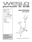
WARNING DECAL PLACEMENT
The decals shown here have been
placed on the resistance system. If a
decal is missing or illegible, call the
toll-free telephone number on the front
cover of this manual and order a free
replacement decal. Apply the decal in
the location shown.
• Misuse of this machine
may result in serious
injury.
• Read user's manual
prior to use and follow
all warnings and
instructions.
hands and
clear of
area.
• Do not allow children
on or around machine.
• Keep body, clothing,
and hair free and clear
of all moving parts.
• Replace label if
damaged, illegible, or
removed.
3
IMPORTANT PRECAUTIONS
4
BEFORE YOU BEGIN
Thank you for selecting the innovative PLATINUM
PLUS BY WELDER ®resistance system. The resistance
system offers a selection of stations designed to develop every major muscle group of the body. Whether your
goal is to tone your body, build dramatic muscle size
and strength, or improve your cardiovascular system,
the resistance system will help you to achieve the specific results you want.
manual. To help us assist you, please note the product
model number and serial number before calling. The
model number is WESY7974.0. The serial number can
be found on a decal attached to the resistance system
(see the front cover of this manual).
To avoid a registration fee for any service needed
under warranty, you must register the resistance
system at www.weiderservice.com/registration.
For your benefit, read this manual carefully before
using the resistance system, If you have questions
after reading this manual, see the front cover of this
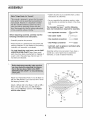
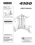
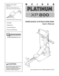
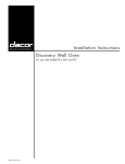
Before reading further, please review the drawing below
and familiarize yourself with the parts that are labeled.
Top Frame
High Pulley
Handle
Console
Squat Arm
Squat Backrest
Squat Pin
Backrest
Storage Knob
Curl Pad
Low Pulley
Seat
Seat Knob
Curl
Base Plate
Leg Lever
ASSEMBLED DIMENSIONS:
5
Height: 85 in.
Width: 47 in.
/
/
216 cm
!19 cm
Depth:
/
239 cm
94 in.
ASSEMBLY
• Tighten all parts as you assemble them, unless
instructed to do otherwise.
• As you assemble the resistance system, make
sure all parts are oriented as shown in the drawings.
E
The included hex keys W and the following
tools (not included) are required for assembly:
• Two adjustable wrenches
Before beginning assembly, carefully read the
following information and instructions:
• One rubber mallet
• One standard screwdriver
• Assembly requires two persons.
• One Phillips screwdriver
• Place all parts in a cleared area and remove the
packing materials. Do not dispose of the packing
materials until assembly is completed.
• Lubricant, such as grease or petroleum jelly,
tape, and soapy water.
• For help identifying small parts, use the PART
IDENTIFICATION CHART. Note: Some small
parts may have been pre-attached for shipping. If
a part is not in the parts bag, check to see if it
has been pre-attached.
Assembly will be more convenient if you have a
socket set, a set of open-end or closed-end
wrenches, or a set of ratchet wrenches.
1,
152
Attach four Plastic Base Feet (71) to the Base (1)
with four M4 Washers (157) and four M4 x 16mm
Self-tapping Screws (104).
1
\
Attach a Wheel (49) to the Base (1) with an M8 x
90mm Shoulder Bolt (125), two M8 Washers
(152), and an M8 Nylon Jamnut (139). Repeat
with the other Wheel.
_71
_
104
157
104
_'71
\
157
104
6
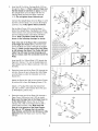
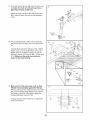
2.
Insert two M10 x 65mm Carriage Bolts (103) up
through the Base (1). Place a piece of tape over
the Bolt heads to hold them in place. Connect
the Upright Base (2) to the Base with the two
Carriage Bolts and two M10 Nylon Locknuts
(!12). Do not tighten these Locknuts yet.
f"--.
,1/07
2 \/4.,_
4/
_
/
Connect the Upright Base (2) to the Base (1) with
two M10 x 67mm Bolts (111) and two M10 Nylon
Locknuts (112). Fully tighten these Locknuts.
Set the Mech Frame (!24) onto the Base (1)
behind the Upright Base. Handtighten two M10 x
73mm Screws (137) and two M10 Washers (129)
into the indicated holes in the Base and Mech
Frame, Note: The Mech Frame will not be
shown in the following
drawings
_27
for clarity.
Note: One end of the Rope (70) is connected
to the Right Arm Frame (17t). Untie the loose
end of the Rope and route it through the Upright
Base (2). Make sure the loose end of the Rope
is still between the 90ram Thin Pulley (88) and
Cable Trap (78) (see the inset drawing), and
that it crosses under the connected end of the
___
137
129
78 88
Rope.
Insert two M14 x 155mm Bolts (107) through the
Right Arm Frame (171) and the Upright Base (2).
Hand tighten two M!4 Nylon Locknuts (!27) onto
the Bolts,
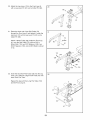
3,
Route the loose end of the Rope (70) through the
Left Arm Frame (8) and a Swivel Arm (29). Make
sure the Rope is under the indicated rod in the
Swivel Arm.
Attach the Swivel Arm (29) to the Left Arm Frame
(8) with an M4 x 5mm Self-tapping Screw (!76).
Attach a "V"-pulley (93) inside the Swivel Arm
(29) with an M10 x 53mm Button Bolt (140) and
an M10 Nylon Locknut (112),
4.
---T--T_
- _--o Z_
Route the loose end of the Rope (70) through a
Rope Cover (169) and a Link (167) as shown.
Make sure the large hole in the Rope Cover is
on the side shown. Secure the set of Rope
Clamps (165, 166) on the Rope with two M5 x
16mm Button Screws (164), Make sure that
Rope is in the grooves of the Rope Clamps,
that there is t/2" between the Link and the
Rope Clamps, and that the two Screws are fully
tightened. Slide the Rope Cover over the Rope
Clamps,
93"
4
164
70
Hole
7
169
166
_i
67
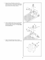
Remove the two M14 Nylon Locknuts (127).
Attach the Left Arm Frame (8) to the Upright Base
(2) with the two M14 x 155mm Bolts (107) used in
step 2 and the two M14 Nylon Locknuts,
107
127
6,
Attach the Backing Plate (59) to the Upright Base
(2) with two M!0 x 65mm Carriage Bolts (103)
and two M10 Nylon Lecknuts (112), Do not tighten the Locknuts yet.
59
\
103
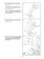
7,
Attach the Squat Backrest (28) to the Squat
Carriage (!0) with four M6 x !6mm Screws (108),
7
108
108
lO
8
8.
Slide the Squat Carriage (10) onto the Upright (3)
as shown. Insert the Squat Pin (35) into an upper
hole in the Upright.
8
35
9,
Press the Front Cover (3!) onto the Upright Base
(2). Make sure the Cover is oriented as shown
in the inset drawing.
9
31
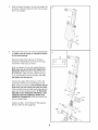
Route the Upper Wire Harness (172) down
through the Upright Base (2) and out the large
round hole in the back, as shown.
Slide the Upright (3) onto the Upright Base (2).
Make sure you do not pinch the Upper Wire
Harnesses (t72). Secure the Upright with two
M!0 Washers (129), two M10 x 20mm Screws
(113), and two M10 x 25ram Screws (105). Do
not tighten the Screws yet.
Connect the Upper Wire Harness (172) to the
Lower Wire Harness (173) extending from the
Mech Frame (not shown). The connector should
slide easily into the socket and snap into place.
If the connector does not slide easily and snap into
place, turn it over and then insert it. IF THE CONNECTOR IS NOT INSERTED PROPERLY, THE
CONSOLE MAY BE DAMAGED WHEN THE
POWER IS TURNED ON. Press the excess wire
159
113
into the Upright Base.
Tighten two M4 x !6mm White ZP Self-tapping
Screws (159) into the Upright (3).
31
172
9
173
10. Insert an M1O x 125mm Button Screw (144)
through an M!O Washer (!29), the Upright (3),
and the Backing Plate (not shown). Bold the Bolt
in place by sticking a piece of tape over the
bolt head.
lO
Tighten the two Mt0 Nylon Locknuts (1t2)
used in step 6. Tighten the two Mt0 x 20ram
Screws (tt3) and two Mt0 x 25ram Screws
(t05) used in step 9.
124
81
129
Attach the Mech Frame (124) to the Base (1) with
two M10 x 73ram Bolts (137) and two M1O
Washers (129), Do not tighten the Bolts yet.
144
Attach the Mech Frame (124) to the Upright (3)
with the M10 x 125mm Button Screw (144). Make
sure the Upright and Mech Frame are properly
aligned before tighten the Screw.
Tighten the four M10 x 73ram Bolts (137) in
the Base (1) and the two Mt0 Nylon Locknuts
(tt2) used in the first paragraph of step 2.
Snap the Side Mech Cover (81) into place on the
Mech Covers (14 and 15).
).
"1
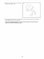
11. Wet a Squat Arm (18) and the inside of a Small
Foam Pad (36) with soapy water. Slide the Foam
Pad onto the Squat Arm.
129_
137
11
137
Grease_
Grease an M10 x 73mm Bolt (137). Attach a
Squat Arm (18) to the Squat Carriage (!0) with
the Bolt, two 24mm Plastic Washers (110), and
an M1O Nylon Locknut (112). Do not overtighten
the Locknut; the Squat Arm should be able to
pivot with intermediate effort.
18
18
112
Repeat this step with the other Squat Arm
(18).
12. Orient the Top Frame (20) with the mark in the
position shown. Attach the Top Frame to the
Upright (3) with two M10 x 65mm Button Screws
(!17) and two M10 Washers (129). Press the
Plastic Cap (46) into the Upright, over the Top
Frame.
12
20
Mark
3
46
10
117 129
13. Attach the Upright Plate (23) to the Upright (3)
with six M4 x 9mm Self-tapping Screws (106).
13
14. Attach the Console (21) to the Upper Wire
Harness (172). The connector should slide easily into the socket and snap into place. If a connector does not slide easily and snap into place,
turn it over and then insert it. IF THE CONNECTOR IS NOT INSERTED PROPERLY, THE CONSOLE MAY BE DAMAGED WHEN THE POWER
IS TURNED ON. Push the excess wire into the
14
158
157
Upright (3).
145
Attach the Console (21) to the Upright (3) with
two M4 x 80mm Self-tapping Screws (145), two
M4 x 65mm Self4apping Screws (158), and four
M4 Washers (!57).
157
15. Orient the Rail (5) with the holes on the side
shown. Attach the Rail to the Upright Base (2)
with an MIO x 106mm Bolt (19) and an MIO
Nylon Locknut (112). Do not overtighten
the
Loeknut;
the Rail must be able to pivot
easily.
15
44
Attach at
this hole
\
5
Holes
Tighten the Storage Knob (44) into the
Upright Base (2) and the Rail (5).
16. Orient the Seat (25) as shown. Attach the Seat to
the Seat Carriage (!6) with four M6 x !6mm
Screws (108).
112-_e.
16
Wide
End
108
108
11
17. Press the Front Leg Foot (38) onto the Front Leg
(4). Note: The front of the Front Leg Foot is
taller than the back of the Foot.
17
95 95
Attach the Front Leg (4) to the Rail (5) with four
M8 x 20mm Screws (95) and four M8 Washers
(152).
152
Front is
taller _38
18. Pull out the Seat Knob (138) as far as it will go,
and set the Seat Carriage (!6) on the Bench Rail
(5).
18
119
Loosely attach two 8mm Spacers (123), a 59mm
Spacer (122), and two Seat Wheels (74) to the
bottom holes in the Seat Carriage (16) with an
M8 Nylon Jamnut (139) and an M8 x 102mm Bolt
(119). Make sure the parts are oriented as
shown in the inset drawing.
123
Side
123
19. Make sure that the wide sides of all six Seat
19
Wheels (74) are pressed against the Rail (5).
While a second person presses down on the Seat
(25), hold the bottom Seat Wheels firmly against
the bottom of the Rail and properly tighten the
indicated M8 Nylon Jamnut (139).
Engage the Seat Knob (138) into an adjustment
hole in the Rail (5).
25
745-
74
12
74
139
138
20. Attach the Leg Lever (13) to the Front Leg (4)
with a Leg Lever Pin (91) and a Cotter Pin (90).
20
91
21. Route the short end of the Split Cable (72)
through the Front Leg (4) and attach it inside the
Leg Lever (13) with a Leg Lever Pin (91) and a
Cotter Pin (90).
21
72
Attach a 90mm Pulley (92) inside the Front Leg
(4), over the Spit Cable (72), with an M10 x
92mm Bolt (116), two M10 Washers (129), two
25mm Spacers (130), and an M10 Nylon Locknut
(112).
91
112
129_ _ 130
22. Insert the two Short Pad Tubes (32) into the Leg
Lever (13). Slide two Large Foam Pads (37) onto
each Short Pad Tube.
22
Repeat this step with the Long Pad Tube (153)
and the Front Leg (4).
4
37
13
23. Attach the Backrest Cap (40) to the Backrest
Frame (17) with two M4 x 16mm Self-tapping
Screws (104).
23
104
%
Attach a Bumper (168) to the Backrest Frame
(!7) with an M4 x 16mm Self-tapping Screw (!04)
and an M4 Washer (157).
168
_.104
157
Attach the Right Pinch Guard (42) to the Backrest
Frame (17) with two M4 x 9mm Self4apping
Screws (106). Attach the Left Pinch Guard (41)
in the same manner.
106
4!
24. Attach the Backrest (24) to the Backrest Frame
(17) with four M6 x 38ram Screws (128) and four
M6 Washers (!26).
24
126
25. Insert the rod on the Backrest Frame (17) into the
slot in the Seat Carriage (!6). Hold the Backrest
Frame vertically over the Seat Carriage and
slide the rod into the slot, as shown in the
inset drawing.
25
14
26. Attach the Curl Pad (26) to the Curl Post (12) with
two M6 x 16ram Screws (108).
26
26
108
27. Make sure that all parts have been properly tightened. The use of the remaining parts will be explained in
ADJUSTMENTS, beginning on the next page.
Before using the resistance system, turn on the console and change the resistance setting as
described in CONSOLE OPERATION on page 20.
15
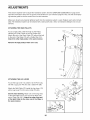
ADJUSTMENTS
This section explains how to adjust the resistance system. See the EXERCISE GUIDELINES on page 23 for
important information about how to get the most benefit from your exercise program. Also, see the accompanying exercise guide to see the correct form for each exercise.
Make sure all parts are properly tightened each time the resistance system is used. Replace worn parts immediately. The resistance system can be cleaned with a damp cloth and a mild, non-abrasive detergent. Do not use
solvents.
ATTACHING THE HIGH PULLEYS
20
To use a high pulley, slide the hook on the Pulley
Housing (27) onto a hook on the Top Frame (20).
Attach the end of the Short Cable (73) without the ball
to the end of the Rope (70) with a Cable Clip (161).
Attach the other high pulley in the same manner.
Remove the high pulleys when not in use.
ATTACHING THE LEG LEVER
4
To use the Leg Lever (13), attach it to the Front Leg
(4) with a Leg Lever Pin (91) and a Cotter Pin (90).
Attach the Split Cable (72) inside the Leg Lever (13)
with a Leg Lever Pin (9!) and a Cotter Pin (90).
See the inset drawing. Attach one of the long ends
of the Split Cable (72) to one end of the Rope (70)
with a Cable Clip (16!), Attach the other long end
of the Split Cable to the other end of the Rope in
the same manner.
72
16
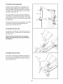
ATTACHING THE ACCESSORIES
To attach a Short Handle (84) to a high pulley, first
attach the pulley housings to the resistance system
(see ATTACHING THE HIGH PULLEYS on the previous page). Then, attach the Handle to a Short Cable
(73) with a Cable Clip (161).
The Long Handles (not shown) and the Ankle Strap
(not shown) can be attached to the Short Cables (73)
or the Rope (not shown) with Cable Clips (161). Attach
the Hip Strap (not shown) to the ends of the Rope with
two Cable Clips.
84
The Ab Strap (not shown) can be attached to the Rope
(not shown) using the two Extension Straps (not
shown) and four Cable Clips (161).
ATTACHING THE CURL PAD
To attach the Curl Pad (26), insert the Curl Post (12)
into the Front Leg (4). Secure the Curl Post with the
Curl Knob (45).
Remove the Curl Pad (26) from the resistance
system when performing an exercise that does
not require it.
ATTACHING THE CURL BAR
To use the Curl Bar (43), first attach the leg lever to
the front leg (see ATTACHING THE LEG LEVER on
the previous page). Attach the Curl Bar to the hook
on the Leg Lever (13).
43
13
17
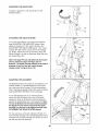
ADJUSTING THE SQUAT ARM
To adjust a Squat Arm (18), pull the Arm to the
desired position.
18
18
A']-rACHING THE SQUAT STATION
_1o
To use the squat station, first remove the backrest
(see ADJUSTING THE BACKREST below). Next,
adjust the squat arm to the forward position (see
ADJUSTING THE SQUAT ARM above). Then, insert
a Squat Pin (35) into the correct hole in the Upright
(3). Finally, attach each end of the Rope (70) to the
Squat Carriage (10) with an Extension Strap (82) and
two Cable Clips (161).
18
82
Note: The Squat Pin (35) will determine the lowest
point to which the Squat Carriage (10) can
descend. The Squat Carriage should not be able to
descend so low that the user could become
trapped
161
under the Squat Arms (18).
ADJUSTING THE BACKREST
24
The Backrest (24) can be used in a level position or an
inclined position. To use the Backrest in a level position, secure the Seat Carriage (16) at the adjustment
hole in the Rail (5) closest to the Front Leg (not shown)
(see ADJUSTING THE SEAT on the next page).
To use the Backrest (24) in an inclined position,
secure the Seat Carriage (16) at one of the other
adjustment holes in the Rail (5). Rest the Backrest
against the Upright Base (2) or the Upright (3). Note:
To use the Backrest in the most inclined position,
the Squat Pin (not shown) must hold the Squat
Carriage (not shown) in the highest position (see
A'TrACHING THE SQUAT STATION above).
For row exercises, remove the Backrest Frame (17)
from the Seat Carriage (16). Hold the Backrest Frame
vertically over the Seat Carriage and lift the rod out of
the slot (see the inset drawing).
5
18
16
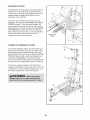
ADJUSTING THE SEAT
The Seat (25) can be secured at various positions on
the Rail (5). To move the Seat, pull the Seat Knob
(138) out as far as it will go and slide the Seat to the
desired position. Engage the Seat Knob into an
adjustment hole in the Rail.
25
\
To perform row exercises, the hip strap must be
attached to the rope (see ATTACHING THE ACCESSORIES on page 17), and the Seat Carriage (16)
must be able to roll along the Rail (5). First, remove
the backrest from the seat carriage (see ADJUSTING
THE BACKREST on page 18). Then, pull the Seat
Knob (138) out as far as it will go, and turn the Seat
Knob so that the pin rests at the end of the "L"shaped slot (see the inset drawing).
Adjustment
Hole
138
Pin
STORING THE RESISTANCE SYSTEM
To store the resistance system, first remove the Curl
Pad (not shown) and the Leg Lever (not shown) from
the resistance system. Secure the Seat (25) at the
position closest to the Front Leg (4) (see ADJUSTING
THE SEAT above). Next, remove the Storage Knob
(44) from the Upright Base (2). Lift the Front Leg
toward the Top Frame (20). Tighten the Storage Knob
into the side of the Upright Base and into the Rail (5).
To move the resistance system, stand behind the
Upright (3) and place the toe of your shoe on the end
of the Base (!). Tilt the resistance system back onto
the Wheels (49) and roll it to the new location.
2
\
44
25
\
19
49
1
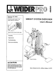
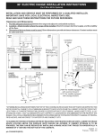
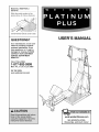
CONSOLE OPERATION
FEATURES OF THE CONSOLE
PLUGGING IN THE RESISTANCE SYSTEM
Plug the indicated
end of the
Transformer (181)
into the Rear Mech
Cover (14). Plug the
other end of the
Transformer into a
120-volt outlet. All
18!
indicators and displays on the console
will flash once; the console will then be ready for use.
The motor may be heard while the resistance system
calibrates itself. Important: Always plug in the transformer when using the resistance system.
PROGRAMS
CERTIFIED_
Console
INCLINE
pR
PEC FLY
CHEST
PRESS
BICEP CURL
SQUAT
EXYENSION
SHOULDER
ADDUCTION
PR
ARMP,alSE
iii!_i
GLUTE KICK
DECLINE EXTE
PRE_
TRICEP
UPPER
_
ABS & BACK
BODY
LEG CUR L
LOWER BODY
MANUAL OPERATION
Program
Buttons
[
[[
Lose
[[
TRAIN
OlROUIT
1. Plug in the transformer.
O_1
o1
WEIGHT
Main
Display
NEXT
Plug the transformer into a 120-volt outlet (see
PLUGGING IN THE RESISTANCE SYSTEM
above). Important: Always plug in the transformer when using the resistance system.
LE5 Lur_L
r, ,o,
CERTIFIED PERSONALTRAINER
Resistance
Display
o]]
EXERCISE
Note: When the power is on, the words MANUAL
MODE will appear in the main display. To use a program, see PROGRAM OPERATION on page 21. If
you want to return to the manual mode while the
console is running a program, press and hold the
NEXT button.
I_I i--I
If no buttons are pressed and no cables are pulled
for ten minutes, the console will go to sleep. Press
any button to resume exercising.
_r
Sets
Display
EsEts-REPs
2. Select a resistance setting.
Reps
The current resistance setting will appear in the
resistance display. To select a different resistance
setting, first make sure that no cables are being
pulled. Next, press the resistance + or - buttons.
Each time a button is pressed, the resistance setting will increase or decrease by 1 pound. To
change the resistance setting quickly, hold down
one of the buttons.
The heart of the resistance system is the digital resistance training console. The console offers both a manual mode and nine workout programs. When the manual
mode is selected, the resistance setting can be
changed with the touch of a button. When a program is
selected, the console will guide you through an effective upper body, ab and back, or lower body workout.
Note: While the resistance setting is changing, the
motor will be heard. To prevent damage to the
motor, do not pull any of the cables while the
resistance setting is changing. If a cable is
pulled, the words RELEASE HANDLES AND
READJUST RESISTANCE AS DESIRED may
appear in the main display.
To use the manual mode of the console, follow the
steps at the right. To use a program, see page 21.
20
3. Enter the numbers of sets and repetitions that
you plan to complete for an exercise.
perform the cardio row exercise while the main display counts down from 5 minutes.
Note: To see the correct form for the cardio row
exercise, see the included exercise guide. If the
resistance setting is too high or too low, select a different resistance setting by pressing the resistance
+ or - buttons.
To enter the number of sets that you plan to do,
press the SETS + or - buttons. To enter the number
of repetitions that you plan to do, press the REPS +
or - buttons.
Note: If you do not enter the numbers of sets and
repetitions that you plan to do, the console will
count the total number of repetitions that you complete during your workout.
4. Adjust the resistance setting and the numbers of
sets and repetitions for the exercise if desired.
The name of an exercise in the program will appear
in the main display. The recommended resistance
setting and the recommended numbers of sets and
repetitions for the exercise will appear in the three
displays below the main display.
4. Perform the exercise.
If you have entered numbers of sets and repetitions, the console will count down the repetitions
and sets you have completed. When you complete
the exercise, repeat steps 2 and 3 above for the
next exercises.
The recommended resistance setting and the recommended numbers of sets and repetitions may be
too high or too low for you, depending on such factors as your body size and your physical condition. If
desired, adjust the resistance setting and the numbers of sets and repetitions by pressing the + or buttons below each display.
5. Unplug the transformer.
When you complete your workout, unplug the transformer from the 120-volt outlet.
5. Perform the exercise.
PROGRAM OPERATION
t.
As you perform the exercise, the console will count
down the numbers of sets and repetitions you have
completed.
Plug in the transformer.
Plug the transformer into a 120-volt outlet (see
PLUGGING IN THE RESISTANCE SYSTEM on
page 20). Important: Always plug in the transformer when using the resistance system.
When you complete the exercise, the word RESTING will appear in the main display. It is recommended that you rest while the main display counts
down.
Note: If no buttons are pressed and no cables are
pulled for ten minutes, the console will go to sleep.
Press any button to resume exercising.
6. Perform the remaining exercises in the program,
After you have completed an exercise in the program, press the NEXT button and the name of the
next exercise will appear in the main display. Repeat
steps 4 and 5 above for the exercise.
2. Select a program.
When the power is on, the words MANUAL MODE
will appear in the main display. To select a program,
press one of the nine program buttons. The indicator on the button you press will light.
Note: The program may include the same exercise
twice, with different resistance settings and different
numbers of sets and repetitions. If you wish to skip
any part of the program, press the NEXT button to
advance to the next part of the program.
Note: The console offers three upper body programs, three ab and back programs, and three
lower body programs. If you wish to exercise your
upper body and if your goal is to lose weight, for
example, press the LOSE WEIGHT button below
the words UPPER BODY.
When you complete the program, the words WORKOUT COMPLETE will appear in the main display.
7. Unplug the transformer.
3. Row for five minutes to warm up.
When you complete your workout, unplug the transformer from the 120-volt outlet.
When a program is selected, the words CARDIO
ROW will appear in the main display. To warm up,
21
TROUBLESHOOTING
RECALIBRATING
THE CONSOLE
To recalibrate the Console (21), first plug in the resistance system (see PLUGGING IN THE RESISTANCE
SYSTEM on page 20). Then, press and hold the
NEXT button and the MOTORIZED WEIGHT
ADJUSTMENT + button for five seconds. When the
buttons are released, a number will appear in the
REPS display. Press the NEXT button again, and
then press the MOTORIZED WEIGHT ADJUSTMENT
+ button; this will start the recalibration process. This
may take a few seconds as the motor moves between
the lowest and highest resistance settings. When the
motor finishes, unplug the transformer from the !20volt outlet.
The Console (21) will be recalibrated. Use the resistance system as described in the CONSOLE OPERATION section, starting on page 20.
TIGHTENING
THE ROPE
29
The type of rope used on the resistance system can
stretch slightly when it is first used. If there is slack in
the rope before resistance is felt, the rope should be
tightened.
70
To tighten the Rope (70), first set the system resistance level to 100 pounds. Locate the end of the Rope
with the Rope Clamps (165, 166) and pull it out until
the Rope is tight. Then, measure the distance between
the Rope Cover (169) and the Swivel Arm (29).
Measure
Distance
Set the system resistance to the lowest level. Have a
second peron pull the Rope (70) out and hold it while
the Rope is adjusted. Push the Rope Cover (!69)
down the Rope and loosen the two M5 x 16mm
Button Screws (164). Pull the Rope through the Link
(!67) and the Rope Clamps (165, 166) to shorten the
Rope by the measured amount. Then, retighten the
two Screws and cover the Rope Clamps with the
Rope Cover. Note: There should be t/2" between
the Link and the Rope Clamps.
169
164
169
70
167
166
22
EXERCISE GUIDELINES
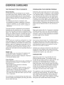
THE FOUR BASIC TYPES OF WORKOUTS
PERSONALIZING
YOUR EXERCISE PROGRAM
Muscle Building
To increase the size and strength of your muscles,
push them close to their maximum capacity. Your muscles will continually adapt and grow as you progressively increase the intensity of your exercise. You can
adjust the intensity level of an individual exercise in
two ways:
• by changing the amount of resistance used
• by changing the number of repetitions or sets performed. (A "repetition" is one complete cycle of an
exercise, such as one sit-up. A "set" is a series of
repetitions.)
Determining the exact length of time for each workout,
as well as the number of repetitions or sets completed,
is an individual matter. It is important to avoid overdoing it during the first few months of your exercise program. You should progress at your own pace and be
sensitive to your body's signals. If you experience pain
or dizziness at any time while exercising, stop immediately and begin cooling down. Find out what is wrong
before continuing. Remember that adequate rest and a
proper diet are important factors in any exercise program.
WARMING UP
The proper amount of resistance for each exercise
depends upon the individual user. You must gauge
your limits and select the amount of resistance that is
right for you. Begin with 3 sets of 8 repetitions for each
exercise you perform. Rest for 3 minutes after each
set. When you can complete 3 sets of 12 repetitions
without difficulty, increase the amount of resistance.
Begin each workout with 5 to 10 minutes of stretching
and light exercise to warm up. Warming up prepares
your body for more strenuous exercise by increasing
circulation, raising your body temperature and delivering more oxygen to your muscles.
WORKING OUT
Toning
You can tone your muscles by pushing them to a moderate percentage of their capacity. Select a moderate
amount of resistance and increase the number of repetitions in each set. Complete as many sets of 15 to
20 repetitions as possible without discomfort. Rest for
1 minute after each set. Work your muscles by completing more sets rather than by using high amounts of
resistance.
Weight Loss
To lose weight, use a low amount of resistance and
increase the number of repetitions in each set.
Exercise for 20 to 30 minutes, resting for a maximum
of 30 seconds between sets.
Cross Training
Cross training is an efficient way to get a complete and
well-balanced fitness program. An example of a balanced program is:
• Plan strength training workouts on Monday,
Wednesday, and Friday.
• Plan 20 to 30 minutes of aerobic exercise, such as
running on a treadmill or riding on an elliptical or
exercise bike, on Tuesday and Thursday.
• Rest from both strength training and aerobic exercise
for at least one full day each week to give your body
time to regenerate.
The combination of strength training and aerobic exercise will reshape and strengthen your body, plus develop your heart and lungs.
Each workout should include 6 to 10 different exercises. Select exercises for every major muscle group,
emphasizing areas that you want to develop most. To
give balance and variety to your workouts, vary the
exercises from session to session.
Schedule your workouts for the time of day when your
energy level is the highest. Each workout should be
followed by at least one day of rest. Once you find the
schedule that is right for you, stick with it.
EXERCISE FORM
Maintaining proper form is an essential part of an
effective exercise program. This requires moving
through the full range of motion for each exercise, and
moving only the appropriate parts of the body.
Exercising in an uncontrolled manner will leave you
feeling exhausted. On the exercise guide accompanying this manual you will find photographs showing the
correct form for several exercises, and a list of the
muscles affected. Refer to the muscle chart on the
next page to find the names of the muscles.
The repetitions in each set should be performed
smoothly and without pausing. The exertion stage of
each repetition should last about half as long as the
return stage. Proper breathing is important. Exhale
during the exertion stage of each repetition and inhale
during the return stroke. Never hold your breath.
23
Rest for a short period of time after each set. The
ideal resting periods are:
• Rest for three minutes after each set for a muscle
slowly as you stretch and do not bounce. Ease into
each stretch gradually and go only as far as you can
without strain. Stretching at the end of each workout
is an effective way to increase flexibility.
building workout.
• Rest for one minute after each set for a toning workout.
STAYING MOTIVATED
• Rest for 30 seconds after each set for a weight loss
workout.
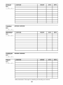
For motivation, keep a record of each workout. The
chart on pages 25 and 26 of this manual can be photocopied and used to schedule and record your workouts. List the date, the exercises performed, the resistance used, and the numbers of sets and repetitions
completed. Record your weight and key body measurements at the end of every month. Remember, the
key to achieving the greatest results is to make exercise a regular and enjoyable part of your everyday life.
Plan to spend the first couple of weeks familiarizing
yourself with the equipment and learning the proper
form for each exercise.
COOLING DOWN
End each workout with 5 to !0 minutes of stretching.
Include stretches for both your arms and legs. Move
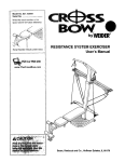
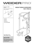
MUSCLE CHART
L
D
S
T
24
A.
B.
C.
D.
E.
R
G.
H.
I.
J.
K.
L.
M.
N.
O.
R
Q.
R.
S.
T.
U.
V.
W.
X.
Sternomastoid (neck)
Pectoralis Major (chest)
Biceps (front of arm)
Obliques (waist)
Brachioradials (forearm)
Hip Flexors (upper thigh)
Abductor (outerthigh)
Quadriceps (front of thigh)
Sartorius (front of thigh)
Tibialis Anterior (front of calf)
Soleus (front of calf)
Anterior Deltoid (shoulder)
RectusAbdominus
(stomach)
Adductor (inner thigh)
Trapezius (upper back)
Rhomboideus (upper back)
Posterior Deltoid (shoulder)
Triceps (back of arm)
Latissimus Dorsi (mid back)
Spinae Erectors (lower back)
Gluteus Medius (hip)
Gluteus Maximus (buttocks)
Hamstring (back of leg)
Gastrocnemius (back of calf)
MONDAY
EXERCISE
WEIGHT
SETS
REPS
WEIGHT
SETS
REPS
WEIGHT
SETS
REPS
Date:
/
/
AEROBIC EXERCISE
TUESDAY
Date:
/
/
WEDNESDAY
EXERCISE
Date:
/
/
AEROBIC EXERCISE
THURSDAY
Date:
/
/
FRIDAY
EXERCISE
Date:
/
/
Make photocopies of this page for scheduling and recording your workouts.
25
MONDAY
EXERCISE
WEIGHT
SETS
REPS
WEIGHT
SETS
REPS
WEIGHT
SETS
REPS
Date:
/
/
AEROBIC EXERCISE
TUESDAY
Date:
/
/
WEDNESDAY
EXERCISE
Date:
/
/
AEROBIC EXERCISE
THURSDAY
Date:
/
/
FRIDAY
EXERCISE
Date:
/
/
Make photocopies of this page for scheduling and recording your workouts.
26
NOTES
27
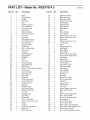
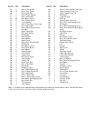
PART IDENTIFICATION
CHART--Model
No. WESY7974.0
M6 x 38mm Screw (!28)
M10 Nylon Locknut (112)
M8 Nylon Jamnut (139)
M10 x 53mm Button Bolt (!40)
M4 x 65mm Self-tapping Screw (!58)
M14 Nylon Locknut (127)
M10 Washer (129)
M10 x 65mm Carriage Bolt (103)
M!0 x 25ram Screw (105)
M10 x 65mm Button Screw (!17)
M8 Washer (152)
M!0 x 67mm Bolt (111)
M10 x 20ram Screw (113)
(
M8 x 20ram Screw (95)
M6 Washer (126)
I
M10
x
73mm Bolt (137)
@B
M4 Washer
(157)
M4 x 80mm Self-tapping Screw (145)
M6 x 16ram Screw (108)
{
M5 x 16ram Button
Screw (164)
M4 x 5mm Self-tapping
Screw (176)
M8 x 90mm Shoulder Bolt (!25)
M!0 x 92ram Bolt (!16)
M4 x 16ram Self-tapping
Screw (104)
(.......................................................................
M4 x 16mm White ZP
Self-tapping Screw (159)
M!0 x !06mm Bolt (19)
M10 x 125mm Button Screw (144)
M4 x 9mm Self-tapping
Screw (106)
M14 x 155mm Bolt (107)
PART LIST--Model
Key No.
1
2
3
4
5
6
7
8
9
10
11
12
13
14
15
16
17
18
19
20
21
22
23
24
25
26
27
28
29
30
31
32
33
34
35
36
37
38
39
40
41
42
43
44
45
46
47
48
49
50
51
52
53
Qty.
Description
1
1
1
1
!
!
1
!
1
1
6
1
1
!
!
1
!
2
1
!
1
4
!
!
1
!
2
1
2
2
1
2
6
2
!
2
6
!
1
1
1
!
1
1
1
1
2
6
2
1
4
1
1
Base
No. WESY7974.0
Upright Base
Upright
Front Leg
Rail
Right Squat Rail
Left Squat Rail
Left Arm Frame
Base Plate
Squat Carriage
M4 x 12ram Screw
Curl Post
Leg Lever
Rear Mech Cover
Front Mech Cover
Seat Carriage
Backrest Frame
Squat Arm
M10 x 106ram Bolt
Top Frame
Console
Gas Spring End
Upright Plate
Backrest
Seat
Curl Pad
Pulley Housing
Squat Backrest
Swivel Arm
50mm x 75mm Plastic Spacer
Front Cover
Short Pad Tube
Wire Harness
Grip Tape
Squat Pin
Small Foam Pad
Large Foam Pad
Front Leg Foot
Bushing
Backrest Cap
Left Pinch Guard
Right Pinch Guard
Curl Bar
Storage Knob
Curl Knob
Plastic Cap
M12 x 72ram Bolt
19ram Round Inner Cap
Wheel
Lat Bar
Squat Carriage Wheel
Mech Arm
Mech Link Arm
Key No.
54
55
56
57
58
59
60
61
62
63
64
65
66
67
68
69
70
71
72
73
74
75
76
77
78
79
80
81
82
83
84
85
86
87
88
89
90
91
92
93
94
95
96
97
98
99
100
101
102
103
104
105
106
R1005A
Qty.
Description
1
!
2
1
2
!
1
4
2
2
2
2
2
2
2
4
1
4
1
2
6
1
1
2
3
!
4
1
2
1
2
2
1
1
!4
1
2
2
3
2
4
4
1
2
2
2
2
1
3
4
16
2
!3
Max Pack Frame
Motor Assembly
Mech Arm Plate
Lower Pulley Plate
M12 Washer
Backing Plate
Rep Counter
Band Wheel
Rod
Steel Washer
Limit Switch
38mm Round Inner Cap
25mm Round Inner Cap
Foam Grip
32mm Round Inner Cap
Arm Bushing
Rope
Plastic Base Foot
Split Cable
Short Cable
Seat Wheel
45ram Square Outer Cap
M10 x 95mm Button Bolt
Gas Spring
Cable Trap
Small Cable Trap
16mm Spacer
Side Mech Cover
Extension Strap
Ankle Strap
Short Handle
Long Handle
Ab Strap
Hip Strap
90ram Thin Pulley
M!2 x 45mm Bolt
Cotter Pin
Leg Lever Pin
90mm Pulley
"V'-pulley
50ram Square Inner Cap
M8 x 20mm Screw
Clip
M10 x 25mm Button Bolt
M6 x 12mm Screw
M10 x 15mm Button Bolt
5ram Spacer
M10 x 95ram Bolt
M10 x 35mm Bolt
M10 x 65mm Carriage Bolt
M4 x !6mm Self4apping Screw
M10 x 25mm Screw
M4 x 9ram Self-tapping Screw
Key No.
107
108
109
110
111
112
113
114
115
116
117
118
119
120
121
122
123
124
125
126
127
128
129
130
131
132
133
134
135
136
137
138
139
140
141
142
143
144
145
146
147
148
Qty.
Description
2
10
1
4
2
28
2
4
2
3
2
1
3
2
2
3
6
1
2
4
2
4
11
2
2
1
4
1
2
2
6
1
5
2
6
1
1
1
2
2
1
2
M14 x 155mm Bolt
M6 x 16mm Screw
M5 x 35mm Bolt
24mm Plastic Washer
M10 x 67mm Bolt
M10 Nylon Locknut
M10 x 20mm Screw
17ram Spacer
32mm Thick Round Inner Cap
M10 x 92mm Bolt
M10 x 65mm Button Screw
M12 Nut
M8 x 102mm Bolt
M10 Lock Washer
M6 Washer
59ram Spacer
8mm Spacer
Mech Frame
M8 x 90ram Shoulder Bolt
M6 Washer
M14 Nylon Locknut
M6 x 38ram Screw
M10 Washer
25mm Spacer
6mm Spacer
Copper Unit
M3 x 20mm Screw
70mm Pulley
Plastic Cap
M6 x 16mm Bolt
M10 x 73mm Bolt
Seat Knob
M8 Nylon Jamnut
M10 x 53mm Button Bolt
M10 x 42mm Button Bolt
M!0 x 46ram Bolt
M10 x 109mm Bolt
M10 x 125mm Button Screw
M4 x 80mm Self-tapping Screw
M6 x 90ram Bolt
77mm Spacer
4mm Spacer
Key No.
Qty.
Description
149
150
151
152
153
154
155
156
157
158
159
1
1
1
8
1
1
2
4
13
2
12
160
161
162
163
164
165
166
167
168
169
170
17!
172
173
174
175
176
177
178
179
180
181
182
183
184
#
#
#
#
4
4
4
4
2
1
1
1
1
2
2
1
1
1
1
4
2
1
1
1
1
1
1
1
0
1
1
2
2
50mm x 75mm Square Inner Cap
45mm Rhombus Inner Cap
45mm Square Inner Cap
M8 Washer
Long Pad Tube
Rail Cap
25ram Square Inner Cap
M4 x 37mm Self-tapping Screw
M4 Washer
M4 x 65ram Self-tapping Screw
M4 x 16ram White ZP Self-tapping
Screw
M6 Nylon Locknut
Cable Clip
M3 Nut
M10 Nylon Jamnut
M5 x 16mm Button Screw
Top Rope Clamp
Bottom Rope Clamp
Link
Bumper
Rope Cover
Spring
Right Arm Frame
Upper Wire Harness
Lower Wire Harness
73ram Spacer
M3 Lock Washer
M4 x 5m m Self-tapping Screw
M5 Washer
Inductor
M5 Nylon Locknut
76mm Spacer
Transformer
M10 x 92ram Grade 8 Bolt
Cover Plate
not used
User's Manual
Exercise Guide
Hex Key
Grease Pack
Note: "#" indicates a non-illustrated part, Specifications are subject to change without notice, See the back cover
of the user's manual for information about ordering replacement parts,
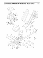
EXPLODED DRAWING A--Model
I
i
No. WESY7974.0
m008A
i
104
74
108119 123
104
/123
1!9
121
128
106,
106
_,
42
26
155
106
112
66
108
5
48
32
153
32
161
72
150
37
91
-4
91
15!_
@38
1!6
37
154
EXPLODED
DRAWING B--Model
No. WESY7974.0
R1005A
47
106
106
67
115
r
36
.145
157
159
68
18
1!0 _'
14%
30
107 103
129
®
93
17! _
107
176
1391
69
112
30 140
152
i_-139
_9
93
164
169
37
i57/_ 71:
104
156
_70S1_
5
166 167
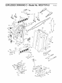
EXPLODED DRAWING C--Model
No. WESY7974.0
m006A
86
22
87
144-
_4
14
lO4
81
#
170
112
104
147
132
13
163.
62
ORDERING
REPLACEMENT
PARTS
To order replacement parts, see the front cover of this manual. To help us assist you, please be prepared to give
the following information:
• the MODEL NUMBER of the product (WESY7974.0)
• the NAME of the product (PLATINUM PLUS BY WELDER resistance system)
• the SERIAL NUMBER of the product (see the front cover of this manual)
• the KEY NUMBER and DESCRIPTION
center of this manual)
of the part(s) (see the PART LIST and EXPLODED DRAWING in the
LIMITED WARRANTY
ICON Health & Fitness, Inc. (ICON), warrants this product to be free from defects in workmanship and
material, under normal use and service conditions, for a period of ten (10) years from the date of purchase. This warranty extends only to the original purchaser. ICON's obligation under this warranty is limited to replacing or repairing, at ICON's option, the product through one of its authorized service centers.
All repairs for which warranty claims are made must be pre-authorized by ICON. If the product is shipped
to a service center, freight charges to and from the service center will be the customer's responsibility. For
in-home service, the customer will be responsible for a minimal trip charge. This warranty does not extend
to any product or damage to a product caused by or attributable to freight damage, abuse, misuse,
improper or abnormal usage or repairs not provided by an ICON authorized service center; products used
for commercial or rental purposes; or products used as store display models. No other warranty beyond
that specifically set forth above is authorized by ICON.
ICON is not responsible or liable for indirect, special or consequential damages arising out of or in connection with the use or performance of the product or damages with respect to any economic loss, loss
of property, loss of revenues or profits, loss of enjoyment or use, costs of removal or installation or other
consequential damages of whatsoever nature. Some states do not allow the exclusion or limitation of incidental or consequential damages. Accordingly, the above limitation may not apply to you.
The warranty extended hereunder is in lieu of any and all other warranties and any implied warranties of
merchantability or fitness for a particular purpose is limited in its scope and duration to the terms set forth
herein. Some states do not allow limitations on how long an implied warranty lasts. Accordingly, the above
limitation may not apply to you.
This warranty gives you specific legal rights. You may also have other rights which vary from state to state.
ICON HEALTH & FITNESS, INC., t500 S. t000 W., LOGAN, UT 8432t-98t3
Part No. 218674 R1005A
Printed in China © 2004 ICON IF',Inc.