1
Item #: V35MWF
Assembly Instructions
For our most current instructions, to request missing, lost or broken parts, or for any other Customer
Service issues, please visit our website at www.walkeredison.com or call us at 877-207-5906.
Revised 07/2011
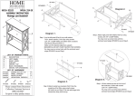
Attach crossbars (4,6) to front panel (2) using screws (A). Attach crossbars (3,5) to front panel (1) using screws
(A). Tighten screws (A) with wrench (H).
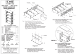
Attach crossbars (3,4) to cable management system (8) using screws (A). Attach crossbars (5,6) to cable
management system (8) using both screws (A) and screws (B). It may be necessary to loosen the screws from
Step 1 slightly to align the crossbars properly with the cable management system. Tighten all screws firmly with
wrench (H).
Attach support bars (7) to crossbars (3,4) and crossbars (5,6) using screws (C). Tighten screws (C) with
wrench (H). Screw suction cups (D) into crossbars (5,6).
Screw pins (E) into cable management system (8). Insert rubber pads (F) into front panels (1,2). Insert suction
cups (G) into cable management system (8).
Screw pins (E) into front panels (1,2).
Carefully slide glass shelves (10) into place. The glass shelves will rest on the pins placed in Steps 4 and 5.
Place glass shelf (9) carefully on top of the stand and gently press down to secure.