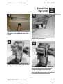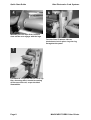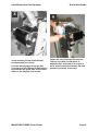
1
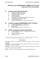
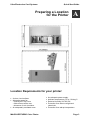
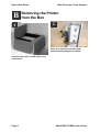
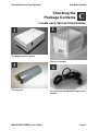
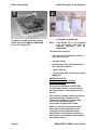
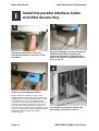
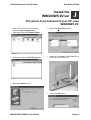
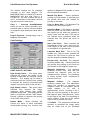
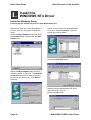
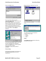
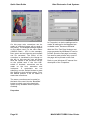
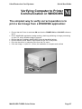
Ultra Electronics Card Systems
Quick Start Guide
MAGICARD TURBO Color Printer
Quick Start Guide for the
TURBO, TURBO M AND TURBO MS
Quick Start Guide
Printer/Software Setup
Iss. 04 Apr 99
3505-22-01
Stock No. M9004-707
DCR 25826 refers
MAGICARDTURBO Color Printer
Page 1
Quick Start Guide
Ultra Electronics Card Systems
Setting up your MAGICARD TURBO Color Printer
takes just three easy steps:
1.
Unpack and install the printer
A
B
C
D
E
F
G
H
I
2.
Load the supplied WINDOWS Driver software.
Jx
Jy
K
L
3.
Preparing a Location for the Printer
Removing the Printer from the Box
Checking the Package Contents
Install the Dye Film
Load the Plastic Cards
Cleaning the Card Cleaning Roller (sticky or tacky roller)
Connect the Printer to a Power Supply
Test the Printer Operation
Install the Parallel Interface Cable and Ultra Secure Key
Install the WINDOWS Driver (WINDOWS 3.x)
Install the WINDOWS Driver (WINDOWS 95)
Printer Setup
Install the WINDOWS Driver (WINDOWS NT4)
Verify computer-to-printer operation.
M
N
P
Q
Verifying Computer to Printer Communication in WINDOWS
In Case of Difficulty.
Important Cleaning procedures.
LED Error Codes
Note: The Ultra WEB site at http://www.ultra.co.uk contains comprehensive technical support information
including the latest downloadable software, WINDOWS Drivers, Technical Bulletins etc
Conventions
Throughout this guide, the following conventions are used to identify important
information.
WARNING - Warning messages indicate where personal injury could result from
not following the correct procedures.
CAUTION - Caution messages indicate where damage to equipment could result
from not following the correct procedures.
NOTE - Notes convey important information that is identified within the text.
Page 2
MAGICARD Color Printer
Ultra Electronics Card Systems
Quick Start Guide
Preparing a Location
for the Printer
A
Location Requirements for your printer:
• A clean, level surface.
• Adequate space for:
- opening the Top Cover
- cable access at the rear.
- allowance for air circulation.
• An adequately ventilated room.
MAGICARDTURBO Color Printer
•
•
•
•
An adequate power supply.
Ambient temperature +10 to +30 deg C.
Relative Humidity 20/70% RH.
Protection from direct sunlight and
chemicals.
• Protection from abrupt temperature
Page 3
Quick Start Guide
B
Ultra Electronics Card Systems
Removing the Printer
from the Box
changes.
1
2
Place on a smooth, level table and
remove the polyethylene container.
Carefully open the box and remove any
accessories.
Page 4
MAGICARD TURBO Color Printer
Ultra Electronics Card Systems
Quick Start Guide
Checking the
Package Contents
C
Locate each item as listed below:
1
2
The MagiCard Color Printer
The Card Cassette
3
Take-up Core
MAGICARD TURBO Color Printer
4
A Power Cord with Moulded Plug for your
Country
Page 5
Quick Start Guide
Ultra Electronics Card Systems
6
5
OPTIONAL STARTER KIT
Envelope containing this Quick Start
Guide and the PrintMAGIC WINDOWS
Driver 3.5" floppy disk.
Note:
This Starter Kit is not supplied
with your printer and must be
ordered separately, Part No
M9004-698.
The Starter Kit contains:
•
One roll of UR1 YMCKO Dye Film for
full colour printing
•
200 PVC Cards
•
25 Cleaning Cards and Cleaning Pen
for Thermal Printhead
•
1 Pair of Gloves
•
1 Centronics IEEE 1284 Parallel Cable,
M2900-337
IMPORTANT NOTE:
Reference Centronics Parallel
Connection Cable:
It is recommended that an IEEE 1284
specification cable be used to connect
the Turbo Printer to the parallel port of
the PC.
This cable has double screening with the
data wires being in twisted pairs to
eliminate crosstalk and noise pickup
found in the standard types of
unscreened parallel printer cable.
Failure to use this specification cable
may lead to image degradation and
corruption of the image data being
downloaded to the printer resulting in a
poor quality or scrambled multi-coloured
card being printed.
Page 6
MAGICARD TURBO Color Printer
Ultra Electronics Card Systems
Quick Start Guide
Install the
Dye Film
1
D
Recesses
3
Open the Printer Top Cover by releasing
the catch on the right-hand side of the
printer.
Replace the Film Carrier
2
By turning the “Dzus” fastener ring a
quarter turn counter-clockwise, the dye
film carrier can be removed.
MAGICARD TURBO Color Printer
4
Open the Dye Film package. Fit the dye
film on the lower boss, observing the
correct orientation of the dye film.
Fit the empty take-up core on the upper
boss, observing the correct orientation of
the notches on the Take-up Core.
Page 7
Quick Start Guide
5
Ultra Electronics Card Systems
6
Manually turn the Spur Gear until the
slots on the core engage with the lugs.
Turn the 'Dzus' Fastener 1/4 turn
clockwise to lock in place. Lay the ring
flat against the panel
7
Pull about 6" of dye film off the roll of dye
film, observing that it should be coming
off the top of the roll, as per the label
illustrations.
Page 8
MAGICARD TURBO Color Printer
Ultra Electronics Card Systems
8
Avoid touching the tip of the thermal
printhead with your hands.
Feed the leading edge of the dye film
over the tip of the Thermal Printhead and
beneath the two guide bars, where fitted.
(Refer to the diagram on the side).
MAGICARD TURBO Color Printer
Quick Start Guide
9
Fasten the end of the dye film onto the
Take-up Core with a small piece of
adhesive tape, and wind on a couple of
turns. Avoid creasing of the dye film and
position it centrally on the core.
Page 9
Quick Start Guide
E
Ultra Electronics Card Systems
Load the
Plastic Cards
1
2
Flex a stack of plastic cards, to make
sure they are not 'stuck' together. Avoid
touching the surfaces to be printed.
Drop the cards flat down into the plastic
Cassette, side to be printed uppermost,
mag stripe to the left and facing down
(if used).
3
Refit the card hopper back into the
printer.
Page 10
MAGICARD TURBO Color Printer
Ultra Electronics Card Systems
Quick Start Guide
Cleaning the Card Cleaning
Roller (sticky or tacky roller)
1
F
2
The 'tacky' roller should be removed for
cleaning before each batch of 100 cards.
To remove the ‘tacky’ roller, release the
locking tab on the left-hand side and, by
putting your fingers beneath it, the roller
can then be removed. Remove surface
dust by using a strip of ‘Scotch’ adhesive
tape, and ‘snap’ back into place.
3
4
Close the Printer Cover and secure the
front latch.
Install the Cassette into the Printer.
MAGICARD TURBO Color Printer
Page 11
Quick Start Guide
G
Ultra Electronics Card Systems
Connect the Printer
to a Power Supply
1
Locate the Mains Switch on the rear
panel.
3
Switch ON. The indicators should all flash
and the motors run briefly. Finally, the
READY LED will remain ON.
2
Plug in the Power Cord. Plug the other
end into a Power Supply socket.
Page 12
MAGICARD TURBO Color Printer
Ultra Electronics Card Systems
Quick Start Guide
Test the
Printer Operation
H
Print an Internally-Generated Test Card to make
sure your printer is working correctly:
1
At the rear of the printer, locate the TEST
Push-button. This is located in the rear
panel, just above the Centronics parallel
interface connector.
Press the push-button momentarily.
2
It will take a few seconds before printing
commences. When finished, a Test Card
will be ejected from the aperture in the
Front Panel.
3
The card should be as shown, with
Yellow-Magenta-Cyan-Black panels, a
Cyan background and Yellow-MagentaCyan graduated scales. This card can
only be printed by a printer in isolation,
when using UR1 Dye Film. Note also that
the internal software version is printed on
the test card.
MAGICARD TURBO Color Printer
Page 13
Quick Start Guide
I
Ultra Electronics Card Systems
Install the parallel Interface Cable
and Ultra Secure Key
1
Switch the printer OFF. Locate the
UltraSecure Interface connector on the
rear panel.
2
3
Plug a good quality, screened Centronics
Interface cable into this socket and
secure the wire latches. Plug the other
end into the Printer connector of your PC
(LPT1 or LPT2)
4
Note the position for the UltraSecure Key
at the rear of the Magicard Printer.
Please note that the UltraSecure logo is now a
standard feature programmed into the firmware of all
TURBO models. It can be switched on/off from within
the OVERCOAT section of the PrintMagic driver.
If you wish to have a CUSTOM LOGO produced you
must ask your dealer for a custom key order form.
Your logo will then be programmed into a key of the
type shown above. When the key is plugged into your
Turbo it will override the internal programme and your
logo will be printed instead of the standard
UltraSecure logo.
Page 14
Connection of the parallel cable to the
rear 25-way connector on the PC.
MAGICARD TURBO Color Printer
Ultra Electronics Card Systems
Quick Start Guide
Install the
WINDOWS Driver
J
Procedure to be followed if your PC uses
WINDOWS 95:
• Start the PC and from the desktop
select the My Computer folder.
Select and open the Printers folder:
• Select and open the Add Printer icon.
• Select the Have Disk button:
• Insert the PrintMagic WINDOWS Driver
Disk into the PC Drive A.
• Select the Next> button:
• Select the OK button:
MAGICARD TURBO Color Printer
Page 15
Quick Start Guide
• Select the Next> button:
Ultra Electronics Card Systems
• If you opt to print a test page, do so
only if the printer is connected,
switched ON, loaded with cards and
dye film and ready to run. The test
page may be incomplete.
Select the Finish button to complete
the installation.
• Select the desired port (usually LPT1)
and select the Next> button:
You may then be offered the choice of
which printer to use as the default printer.
Select the PrintMagic MAGICARD
Printer and then select the Next> button:
Page 16
MAGICARD TURBO Color Printer
Ultra Electronics Card Systems
K
Quick Start Guide
Printer
Setup
Printer Setup procedure to be followed if the default
settings differ from your requirement:
Printer Setup
Changes to the printer setup options
performed via the Control Panel are
non-volatile, until subsequently
changed, even though the PC may be
switched off after use. Most software
applications provide the means to
change the printer setup but be warned
- these settings may prove to be
volatile with some applications and
your settings may be lost. Play safe
and use the Control Panel.
If you need to alter the default settings,
the PrintMagic™ printer driver provides
you with easy-to-use tab dialog boxes.
Along the bottom of the setup dialog
boxes is a row of four Pushbuttons,
OK, Cancel, Defaults and Help.
Initialise the Setup
Initialise the setup by pressing the
Default pushbutton.
Image Aspect
For WINDOWS 3.x
• Start WINDOWS and in the MAIN
group, select and open the CONTROL
PANEL window.
• Select and open the PRINTERS icon.
• The PRINTERS dialog box appears.
• Highlight the PrintMagic MAGICARD
Printer Driver and from the Options
menu, select PRINTER SETUP.
• The PrintMagic Printer Setup window
appears, which has six pages, any of
which may be viewed by clicking on the
appropriate tab.
For WINDOWS 95
• Go to the "My Computer" folder.
• Double Click on the Printers folder.
• Double Click the PrintMagic
MAGICARD Printer icon.
• Select "Printer" from the menu and go
to Properties.
• Select the Details tab.
• Select the Setup button.
Setup Options
The PrintMagic™ printing system is
designed to provide the best print
output default settings for your printer.
MAGICARD TURBO Color Printer
On this page, the card orientation may be
set. There are four options:-
§ Standard
§ Rotate 180 Degrees
§ Full Card
§ Full Card 180
Prints images on a
card with a border,
(MAGICARD 300 and
MAGICRD 300 Plus)
As Standard, but
rotated 180 degrees
Full-bleed printing up
to the card edges.
(MAGICARD 300 Plus
and Turbo models).
As Full Card but
Page 17
Quick Start Guide
Degrees
Ultra Electronics Card Systems
rotated 180 degrees.
Opposing Rotation Between Sides is only
significant if interfacing to a Magicard Flip
Double-Sided printing model.
Display Popup, when selected will enable
the Magicard printer spooler that normally
is displayed on the bottom right hand side
of the PC VDU when printing.
The number of copies may be set from 1
to 255.
Colour Format / Film
the range of 0 to 254 otherwise if the
value of 255 is used (full black) the YMC
panels will be skipped and only K will be
printed.
Black to K Only - this option when
selected will enable the printing of objects
such as lines, rectangles and graphics
providing they are in a full black value of
255, should a value of 254 or lower be
used the YMC panels would be used to
create the black. This option should NOT
be used if a coloured background is being
used on the card, as white lines may be
present around the edge of the graphics
or objects. To print objects using the resin
K panel Black to YMC and K should be
selected, this will enable a coloured
background to be used with the resin
black printed on top.
Overcoat
Dye Film Fitted - tells the printer which
type of dye film you have installed. The
dye film supplied with your printer is five
panel UR1 dye film. Leave the default
selection at YMCKO - Resin. Note that
UR8 dye film is only valid for the Magicard
Flip Model.
Page 1 Color Format - tells the
WINDOWS Driver which dye film panels
to use on your card. For printing on the
resin black dye panel leave the default
selection at YMCK - Resin Black. For a
simple color image select YMC-Composite
Black.
Page 2 Color Format - applies only to
Magicard Flip models.
Black to YMC and K - this option when
selected will enable the printing of the
resin black panel over the top of the YMC
panels, this will enable masked barcodes
to be printed. Care should be taken to
ensure that the background colour is in
Page 18
Page 1 - Overcoat check box can be
used to turn overcoating on and off.
Page 1 - Ultra Secure check box can be
used to turn this security feature on and
off. An Ultra Secure key must of course
be fitted if a CUSTOM feature is required.
Page 1 - Overcoat Areas/Windows can
select the options for specific areas of the
card to be overcoated, or for windows to
be left in the overcoat (up to five in each
case). Overcoating is a 2.5 micron layer of
transparent acrylic protection that is
available with some types of dye film (For
example the "O" in "YMCKO" dye film).
MAGICARD TURBO Color Printer
Ultra Electronics Card Systems
Quick Start Guide
The default settings are for complete
coverage to the card margins. For
MAGICARD 300 it is 0,36,947,631 and for
MAGICARD 300 plus and Turbo it is
0,0,985,641. The four numbers are the X
and Y coordinates of the bottom left and
top right corners of each area.
applies to Magicard Flip models so leave
this checkbox switched off.
Page 1 - Overcoat Areas/Windows
check box can be used to provide a preselected wide or narrow overcoat window
for magnetic stripe and smart cards with a
chip.
Print on Back Only - For Magicard Flip
models only, leave unchecked.
Page 2 Overcoat - settings apply only to
Magicard Flip models.
Card Settings
Manual Flip Mode - Allows operators,
running non-Flip models, to manually turn
the printed card over and reinsert for
printing on the back.
Hand Fed Mode - If this switch is checked
then the printer will not feed a card from
the hopper but will allow the operator to
insert a card from the front. If the card is
not inserted when prompted within 20
seconds then the printer will return to
standby.
Auto Card Feed - When checked will
automatically feed a new card from the
card hopper to the start of print position
on completion of a printed card.
Laminate Back Side - This is for Flip
models only. This box when checked will
instruct the Flip Printer to eject the card
with the original underside facing up.
Encode Only - No Print - For magnetic
encoding models only . Checking this box
will prevent any printing on the card, but
will encode on the magnetic stripe only.
PRINT QUALITY OPTIONS:
High Quality Resin – This option when
selected will improve the quality of the
printing of barcodes by reducing vertical
distortion. This setting can be used in
conjunction with the “Resin Power” setting
to optimise the printing of barcodes and
images using the K panel of the dye film.
High Quality Colour – This option when
selected may improve the image
resolution when printing high quality
graphical image files. This setting can be
used in conjunction with the “YMC Power/
Density” settings to optimise the printing
of the YMC color panels.
Duplex Mode - When checked, will
convert the driver to allow automated
double-sided printing. this function only
MAGICARD TURBO Color Printer
Magnetic Verification - For magnetic
encoding models only. With this box
checked the magnetic code will be
validated before printing. For interfacing
to earlier models, leave unchecked to
prevent file errors.
Magnetic Position - For magnetic
encoding models only. This adjustment
allows the operator to reposition the
magnetic stripe to accomodate various
swipe
readers.
A
1%
shift
is
approximately 0.1mm. Scrolling to the L
(left) will move the position of the start of
the magnetic data ( Start Sentinel ) closer
to the edge of the card. For interfacing to
earlier models, leave set at the default
value of 50, to prevent file errors.
Y Position - This adjustment allows the
operator to centralise the image which
may be offset due to the printhead
Page 19
Quick Start Guide
Ultra Electronics Card Systems
position. A 1% shift is approximately
0.1mm
close the setup window and to accept any
changes that have been made.
X Start Position - This function allows the
operator to adjust the position of the start
of the image. A 1% shift is approximately
0.1mm. For interfacing to earlier models,
leave set at the default value of 50, to
prevent file errors.
Note: Although you may be able to
access the Printer Setup dialog window
from within a WINDOWS application, with
some applications, the selected settings
will prove to be volatile, and will be lost
when you quit WINDOWS.
X End Position - This function allows the
operator to adjust the position of the start
of the image. A 1% shift is approximately
0.1mm. This adjustment only applies to
Full Bleed models. For interfacing to
earlier models, leave set at the default
value of 50, to prevent file errors.
Click on the RESTORE button to return to
the original default values.
Click on the CANCEL button to close the
setup window and to abandon any
changes that have been made.
For further information on installing and
configuring printers to your PC, operating
in a WINDOWS environment, consult the
Microsoft WINDOWS User's Guide.
Printing Monochrome Bitmaps
Driver versions 4.01 and later has an
option to print graphics using the resin
black panel of the dye film. To print a
bitmap on the resin black panel the format
must be as a 1 Bit Bitmap image file.
YMC Power - allows the user to adjust the
density of the Yellow, Magenta and Cyan
print. For interfacing to earlier models,
leave set at the default value of 50, to
prevent file errors.
Resin Power - allows the user to adjust
the density of the Black Resin print.
Overcoat Power - allows the user to
adjust the density of the Overcoat print.
For interfacing to earlier models, leave set
at the default value of 50, to prevent file
errors.
Colour Adjust
Mag Encoding using the WINDOWS
Driver
If you wish to use the magnetic encoder
from within a WINDOWS application,
create a text string with a tilde (~) symbol
at the beginning and place the string
anywhere on the image, using a black
true type font.
For example, to encode the word
"HELLO" on to Track 1 at 210 bpi on a
HiCo card, the instructions and data string
placed on the image should be:~1,BPI210,MPC7,COEH,%HELLO?
The default values for the Contrast,
Brightness and color balance of the
printed card may be changed in this setup
tab. Unless you know what you are doing,
avoid changing the defaults.
The Magicard 300M printer allows you to
encode HiCo and LoCo cards, at 75 or
210 bpi, on any of the three tracks, at 5 or
7 bits per character, with complete
freedom.
About
To ensure the encoded card is recognised
by the swipe reader the encoded data
must comply with the ISO Standards. For
copies of specifications contact:
Data on this page is for information only.
When the printer set up selections have
been made, click on the OK button to
Page 20
American National Standards Institute
11W. 42ND Street
MAGICARD TURBO Color Printer
Ultra Electronics Card Systems
New York, New York 10036
Tel: (212) 642-4900
Parallel Port Configuration
Quick Start Guide
switch to the ECP version later when you
are ready, or when you install new system
hardware.
Non-ECP Operation
If you are using Windows 3.x or if you are
using Windows 95 but are unfamiliar with
the process of reconfiguring your parallel
port for ECP operation, we suggest you
use the driver in its “NON-ECP” mode.
This is the default mode, and you do not
have to do anything other than install the
driver to use it. The NON-ECP mode is
compatible with Windows 3.x and
Windows 95 and uses the parallel printer
port in its conventional “Centronics”
configuration. In this mode download will
take around 17 seconds.
ECP Operation
The ECP mode of the driver can be used
only with Windows 95 and uses the
parallel port in its “Enhanced Capability”
mode to provide a faster download time of
around 7 seconds.
Unfortunately, although most PC’s are
stated to be “ECP compatible” there are
still many so called compatible PC’s
which cannot be properly configured to
operate efficiently in ECP mode, either
because the interface hardware on the
motherboard is incompatible, or because
the BIOS firmware does not fully support
ECP mode.
There have even been some reports of
Windows 95 itself containing bugs which
interfere with ECP operation under certain
conditions.
To use this mode you need to select ECP
mode for the LPT1 port using the control
panel, and you may also need to set up
your BIOS to operate efficiently in ECP
mode.
Which Mode Should I Use
Windows 3.x: Use the NON-ECP mode.
Windows 95: If you are unhappy about
reconfiguring your computer’s BIOS, or
are uncertain whether your computer is
fully ECP compliant, we suggest you use
the NON-ECP mode. You can always
MAGICARD TURBO Color Printer
Page 21
Quick Start Guide
L
Ultra Electronics Card Systems
Install the
WINDOWS NT4 Driver
Install the Windows Driver
Procedure to be followed if your PC uses Windows NT 4.0:
Start the PC and log in as Administrator to
be sure you have the rights to install the
driver.
Select the My Computer folder and open
the Printers folder. Double click the Add
Printer icon.
Select one or more of the available ports
to print to. With the Add Port.. option a
printer port can be added.
Select the Have Disk button:
Select the My Computer radio button to
install the driver on your PC. The Network
printer server option is used to connect
to a printer on another PC. Click Next to
continue.
Insert the Ultra card Windows NT driver
disk into the PC drive A:.
Select the OK button:
Page 22
MAGICARD TURBO Color Printer
Ultra Electronics Card Systems
Select the Next button:
Fill in the printer name (max. 32
characters, default Ultra card printer) and
select the Next button.
Now indicate whether you would like to
share the printer with other network users.
If you will share the printer, fill in a Share
Name for the printer and select one or
more operating systems that will be used
by the other PCs. Select Next to
continue.
Quick Start Guide
Select the Ultra card printer from the
Printers folder:
Select Document defaults... from the File
menu.
The dialogue that will be displayed
consists of three ‘tabs’:
•
•
•
Setup
Options
Color
Setup
If the Setup tab is selected the following
settings can be made:
In the following dialogue select if you want
to print a test page from Windows?
Select the Finish button. Now the printer
driver files will be copied.
A test page (card) will be printed, if
selected.
Printer Setup
Printer Setup procedure to be followed if
the default setting differs from your
requirement:
MAGICARD TURBO Color Printer
Page 23
Quick Start Guide
Paper Size
Copy Count
Film Type
Duplex
Orientation
Use Paper Size to
determine the printed area
of the card. Standard Size
or Full Bleed (Magicard 300
plus only) can be selected.
Sets the number of copies
printed of each card.
Tells the printer which kind
of dye film you have
installed. The following film
types are available:
YMCKO-Resin
YMCKO-Diffusion
YMCKO-Short Panel
KO-Resin
KO-Diffusion
K-Resin
K-Diffusion
YMCKOK-Resin
Tells the printer if one or
two sides of the card must
be printed.
Determines if the card will
be printed in portrait or
landscape.
Options
If the ‘Options’ Tab is selected, you will
find the following options:
Ultra Electronics Card Systems
Data Transfer Format
This option will speed up the downloading
process from the PC to the printer. To
enable this option click on the
“Compressed Box” so a tick appears in
the window of the box.
Click on the downward pointing arrow
directly below the compressed box and
select one of the following settings: 4, 5,
6, or 7 bit options. The lower the number
of bits the faster the download speed.
Please note:
The maximum 4-bit Data Transfer Format
when selected may produce picture
quality degradation when printing highresolution graphics files. To reduce this
effect select the 5-bit data transfer format.
Overcoat Settings
In this section of the ‘Options’ page, the
overcoat can be enabled and the overcoat
area can be defined.
BLX
BLY
TRX
TRY
Page 24
BLX is the bottom left Xcoordinate
BLY is the bottom left Ycoordinate
TRX is the top right Xcoordinate
TRY is the top right Ycoordinate
MAGICARD TURBO Color Printer
Ultra Electronics Card Systems
Area
Window
Quick Start Guide
If area is selected the
coordinates define the start
and end of the overcoat area
If window is selected the
coordinates define the start
and end of the area that has to
remain blank (no overcoat)
It is possible to define up to 10 overcoat
areas or windows, they will be combined
to one area or window on the card.
Prev
Next
Switch to previous overcoat area
(or window)
Switch to next overcoat area (or
window )
Enable Enable checkbox can be used to
turn overcoat feature on and off.
Note that the enable checkbox is
valid for all overcoats (1 - 10)
Film Power Setting
The film power settings allow the user to
adjust the density for the YMC, the Resin
and the Overcoat print. If using earlier
models, please leave the settings at
default value of 50, to prevent file errors.
Black Format Options
The black format options enable the
operator to use resin panel for fonts only,
for every black spot on the card or not at
all.
Ultra Secure Feature
With this checkbox the user can switch
the Ultra Secure feature on and off,
provided the Ultra Secure Key is installed
on the printer.
180 Degree Rotation
This option is used to rotate the complete
card layout 180 degrees to adjust for the
chip position (on left or right side of the
card) or the magstripe position (on the top
or bottom of the card).
Back Side
If Duplex mode is enabled (in Setup), this
button can be used to switch the ‘Options’
dialogue to back side, to set the options
for the back of the card. The dialogue for
the back will look as follows:
MAGICARD TURBO Color Printer
The same options can be set as for the
front. With the ‘Front Side’ button, the
user can switch back to the front. Note
that in Duplex Mode the options ‘Back
Side Only’, ‘Manual Flip Mode’ and
‘Magstripe Only’ are not applicable and
therefore not available.
Hand Fed Mode - If this switch is checked
the printer will not feed a card from the
hopper but will allow the operator to insert
a card from the front. It the card is not
inserted within 20 seconds when
prompted then the printer will return to
standby.
Back Side Only - This option will only
work on Magicard Flip models as they
have the ability to print double sided
cards. The image will allow a magnetic
stripe card to be encoded and printed on
the back only. `
Manual Flip Mode - Allows operators,
running non-flip models, to manually turn
the printed card over and reinsert for
printing on the back.
Magstripe Only - For magnetic encoding
models only. Checking this box will
prevent any printing on the card, but will
encode on the magstripe only.
Color
Page 25
Quick Start Guide
On this page color corrections can be
made (a corrected image will be send to
the printer). The available settings depend
on the ribbon used. For the color ribbon
(YMCKO Resin - UR1 in the example),
blue, green and red intensity and contrast
can be corrected. The effect of the
correction is visualized by the bitmap on
the left. In this way the user will know
what the impact of the correction will be
on the printed card. If the ‘Use HSL’
switch is checked, corrections can be
made on the hue, saturation and
luminance. If corrections are not
satisfying, use the ‘Default’ button to reset
the settings to their default values. From
the default position it will be easier to
make new corrections.
Ultra Electronics Card Systems
In ‘Properties’ no device settings can be
made. All settings for the Magicard are
available under ‘Document Defaults’.
With the ‘Print Test Page’ button a test
page generated by Windows NT can be
printed. Since the test page is normally
not used for card printers only a part of
the page will be printed on the card.
Refer to your Windows NT manual for a
description of the ‘Properties’.
The same corrections can be made for
the back of the card. Use the ‘BackSide’
button to switch over to the back (this
option is only available when Duplex is
enabled).
Properties
Page 26
MAGICARD TURBO Color Printer
Ultra Electronics Card Systems
Quick Start Guide
Verifying Computer to Printer
Communication in WINDOWS
M
The simplest way to verify correct operation is to
print a test image from a WINDOWS application:
• Ensure that the Printer is switched ON and that the POWER ON and ON LINE indicators
are lit.
• Run a WINDOWS application (badge-making, desk-top publishing or image processing)
on your PC, with a suitable image or artwork.
• Ensure that the PrintMagic MAGICARD Printer is the default printer.
• Ensure that the printer cable is connected from the PC to the printer.
• Print the document, by selecting Print from the File menu.
• If the test image - or part of it - prints, the installation is complete and verified.
MAGICARD TURBO Color Printer
Page 27
Quick Start Guide
N
Ultra Electronics Card Systems
In Case of
Difficulty
Check the Installation:
•
•
•
•
•
•
•
•
•
Repeat the Installation Steps in this Guide.
Check that all cables are correctly connected.
Check the Printer Setup in the WINDOWS Driver.
Check the dye film and cards are correctly loaded.
See what happens in the PrintMagic print manager (the icon appears on the Desktop
during printing and the print status can be checked).
Does the PrintMagic DeSpooler window appear on the application, and clear after
downloading the image to the printer, or does a red cross appear?
Does the ON LINE indicator flash during image downloading to the printer?
If the printer error indicators come on, which ones, and what is the flashing code? ( refer
to the section on LED error codes ).
Does the printer need cleaning? (Refer to the Section on this page)
For Further Assistance:
• There are a number of useful Technical Bulletins on the MAGICARD WEB page at
http://www.ultra.co.uk/ultra/techbltn.html - you will need a User Name and Password.
If you do not have WEB access, copies can be requested from Customer Service. This
is the current list:
Bulletin No.
101
102
103
104
105
106
107
108
109
110
111
Note:
Description
Networking Magicard Printers
Windows Drivers - Important Installation Information
Configuring your PC to use ECP Protocol
Setting-up Procedure for the MAGICARD 300plus Thermal Printhead
MAGICARD PCinside - Interconnection
MAGICARD PCinside - Installation of a CD-ROM Drive
MAGICARD PCinside - Selection of a Video Monitor
MAGICARD PCinside - Video Cameras and Frame Grabbers
ID Badging Software Packages for WINDOWS
MAGICARD Cleaning Procedures
International Safety Standards and the Magicard 300 Range
This List is updated frequently.
• Call your local Dealer, giving the Model Number and Serial Number, a description of the
nature of the problem, and the flashing error codes if present.
• Call the Ultra Magicard Customer Service Hotline number - +44 (0)1305 762115
Page 28
MAGICARD TURBO Color Printer
Ultra Electronics Card Systems
Quick Start Guide
Important Cleaning
Procedures
P
It is very important that the MagiCard Printer be cleaned at regular intervals in
accordance with these instructions. Cleaning Cards and a Cleaning Pen are
included with every printer shipped.
Thermal Printhead Cleaning
It is recommended that the Thermal Printhead be cleaned after every roll of dye film, i.e.
after every 250 cards printed.
CAUTION Failure to clean the Thermal Printhead after every roll of dye film can result
in the build up of residues which cause white lines and streaks in the printed image.
The Thermal Printhead is a fragile and expensive item. Care should be taken to avoid
damage to the printing surface at its lower edge. The surface of the Thermal Printhead
should not be touched with the fingers and under no circumstances should any hard,
sharp or abrasive materials be allowed to contact it.
WARNING The recommended cleaning materials are inflammable. Clean the Thermal
Printhead in a well-ventilated area and avoid naked flames. Extinguish any cigarettes.
Clean the Thermal Printhead as follows:
1. Switch the printer OFF and isolate from the mains power supply.
WARNING The MagiCard Printer contains potentially lethal voltages.
2. Release the top cover catch on the right-hand side of the printer cover.
3. Lift up the Top Cover to the vertical position, as illustrated.
MAGICARD TURBO Color Printer
Page 29
Quick Start Guide
Ultra Electronics Card Systems
Mechanism
Top Cover
Dye Film
Carrier
Thermal
Printhead
Dzus Fastener
4. Whilst changing the dye film, and with the dye film removed, gently wipe the tip of the
Thermal Printhead, using a gentle side-to-side action, with the Felt Tip Cleaning Pen
supplied.
5. Using a tissue, remove any deposits from the pen tip and replace the pen cap to avoid
solvent evaporation. Allow the solvent to evaporate fully from the printhead before
proceeding to fit the new roll of dye film.
Cleaning the Tacky Roller
NOTE - It is very important that these Cleaning Instructions are adhered to in order to
maintain the MagiCard print quality.
A Tacky Roller is located between the Cassette and the upper brushstrip. Its purpose is to
pick up loose debris, fibres and particles from the upper surface of each card which would
otherwise cause a blemish on the finished printed card. Depending on the type of cards
used it is recommended that the Tacky Roller is cleaned each time the Card Cassette is
filled, to recover its stickiness. Clean the Tacky Roller using a piece of Scotch adhesive
tape. Refer to Section E to see how to remove the Tacky Roller.
Cleaning the Rubber Rollers
It is recommended that the Rubber Rollers in the transport mechanism be cleaned after
every 1000 cards printed, using the recommended solvent-impregnated Cleaning Card as
follows:
CAUTION: Failure to clean the Rubber Rollers may result in mis-registration of images
and problems in feeding cards out of the Cassette.
WARNING The recommended cleaning materials are inflammable. Clean the Thermal
Printhead in a well-ventilated area and avoid naked flames. Extinguish any cigarettes.
Page 30
MAGICARD TURBO Color Printer
Ultra Electronics Card Systems
Quick Start Guide
1. Lift up the Top Cover to the vertical position, and remove the Cassette. Switch ON the
power supply.
2. Get the motor to turn the rollers by operating the Microswitch in the front of the print
engine, by hand. Allow the motors to achieve full operating speed before applying the
Cleaning Card to the rollers, otherwise the motors will stall and the rollers fail to turn.
3. Clean the Front Rubber Drive Roller every 1000 cards printed or if mis-registration
occurs. Open a fresh solvent impregnated Cleaning Card and clean the Front Rubber
Drive Roller by inserting the Cleaning Card from the front with the impregnated side
faced down, with the rollers turning so that the roller turns against the Cleaning Card as
shown in Position A.
4. Clean the Printhead Roller, normally positioned beneath the Thermal Printhead, by
applying the Cleaning Card (with the impregnated side faced down) to the visible
surfaces of the Printhead Roller so that the roller turns against the Cleaning Card as
shown in Position D.
NOTE Discard the Cleaning Card when it has dried out. One or two cards should be
sufficient to carry out these instructions.
5. Clean the Rear Rubber Drive Roller by inserting the Cleaning Card with the impregnated
side faced down, from the rear with the rollers turning (ie, beneath the Card Preventer
and the Sticky Roller) so that the lower roller turns against the Cleaning Card as shown
in Position E.
6. Clean the Card Feed Rollers every 1000 cards printed or if problems occur with cards
feeding from the Cassette. Using the Cleaning Card clean the two Card Feed Rollers.
One is normally beneath the Card Cassette and the other is close to theSticky Roller.
These rollers are geared together and cannot be turned by operating the Microswitch as
above. Turn one Card Feed Roller by hand whilst applying the Cleaning Card, with the
impregnated side faced down, to the other Card Feed Roller. Repeat the cleaning
process for the other Card Feed Roller as shown in Positions B and C.
Micro
Switch
MAGICARD TURBO Color Printer
Page 31
Quick Start Guide
Ultra Electronics Card Systems
Cleaning the Optics
1. Ensure the two light emitting diodes (LED's) adjacent to the Thermal Printhead, are clean
and not obscured, the felt tip cleaning pen can be used as in diagram 1.
2. Check that the two apertures to the two optical sensors (one is 3mm diameter, the other
is a fine slit in a stainless steel strip) are not obscured by debris, the felt tip pen can be
used as in diagram 2.
Cleaning the Magnetic Head (if fitted)
1. The Magnetic Encoding Head is located beneath the second top pinch Roller. To clean
the Magnetic Head, insert the Cleaning Card into the mechanism from the rear of the
roller and withdraw several times until the head is clean, as shown is diagram 3.
2. The Magnetic Encoding Head can be seen pictured in diagram 4, with the front cover of
the printer removed and the top pinch roller lifted.
CAUTION : Take great care not to scratch the surface of the magnetic head with any
sharp or abrasive material.
Magnetic Head
Encoding Pinch
Roller
Top Front
Idle Roller
Magnetic
Encoding Head
Magnetic Head
Encoding Pinch
Roller
Page 32
Bottom Front
Driven Roller
MAGICARD TURBO Color Printer
Ultra Electronics Card Systems
Quick Start Guide
LED Error
Codes
Q
The MAGICARD printer has extensive error trapping facilities, to
provide the operator or service agent with fault diagnosis
information.
READY and ERROR Indicator Flashing
The READY indicator flashing indicates that the printer is receiving and processing a file of
image data.
If the ERROR indicator is also illuminated continuously, it indicates that the file of image
data is incomplete and that the printer is waiting for the rest. If this need cannot be met
(perhaps the PC develops a fault or is reset), then the printer must be rebooted by switching
off then on again. Ensure that any files in the Windows Spooler are aborted first.
If the ERROR indicator is also flashing this condition indicates an error in the file
downloaded from the PC and the printer must be powered down. To ensure that the error
will not repeat after reset, abort the transfer on the PC before resetting the printer by
opening and closing the lid.
MEDIA Indicator On
This indicates any of the following:
1.
2.
3.
4.
5.
Dye film has run out.
The wrong dye film has been fitted with respect to the driver settings.
The dye film is jammed.
The card hopper is empty.
A card is jammed in the mechanism.
MEDIA OUT Indicator Flashing
This indicates that the printer is in hand fed mode and is waiting for the operator to
manually insert a card through the front aperture.
READY Indicator Flashing
This indicates that the printhead is too hot. The printer waits for it to cool down before
Continuing with the print. If it does not cool down within about 60 seconds, the printer will
indicate an ERROR as described below.
ERROR Indicator Flashing
This indicates a system hardware fault. The indicator will flash a number of pulses, pause,
and then repeat. The number of flashes indicates the cause of the error. Note the number
of flash pulses and contact your service agent.
ERROR and READY Indicators Flashing
This indicates a system hardware fault. The indicators will flash a number of pulses, pause,
and then repeat. The number of flashes indicates the cause of the error. Note the number
of flash pulses and contact your service agent.
MAGICARD TURBO Color Printer
Page 33
Quick Start Guide
Ultra Electronics Card Systems
Notice
The information contained in this document is subject to change without notice.
Ultra Electronics Limited shall not be liable for errors contained herein or for incidental consequential
damages in connection with the furnishing, performance or use of this material.
This document contains proprietary information belonging to Ultra Electronics Limited and may not
wholly or partially be copied, stored in a data retrieval system, disclosed to third parties or used for
any purpose other than that for which it was supplied, without the express written authority of Ultra
Electronics Limited. All rights are reserved.
© Ultra Electronics Limited, 1998
Federal Communications Commission (FCC) Statement
Warning: This equipment generates, uses, and can radiate radio frequency energy and if not installed
and used in accordance with the instructions manual, may cause interference to radio
communications. It has been tested and found to comply with the limits for a Class A computing
device pursuant to Subpart J of Part 15 of FCC Rules, which are designed to provide reasonable
protection against such interference when operating in a commercial environment.
Operation of this equipment in a residential area is likely to cause interference in which case the user
at his own expense will be required to take whatever measures may be required to correct the
interference.
Note: Changes or modifications not expressly approved by the party responsible for compliance could
void the user's authority to operate this equipment.
Canadian Department of Communications Statement
This digital apparatus does not exceed the Class A limits for radio noise emissions from digital
apparatus set out in the Radio Interference Regulations of the Canadian Department of
Communications.
Le présent appareil numérique n'émet pas de bruits radioélectriques dépassant les limites applicable
aux appareils numériques de la class A prescrites dans le Règlement sur le brouillage radioélectrique
édicté par le ministère des Communications du Canada.
WINDOWS is a trademark of Microsoft Corporation.
MAGICARD 300 is a trademark of Ultra Electronics Limited.
PrintMagic is a trademark of Software 2000 Limited.
IBM, AT and PC are trademarks of International Business Machines Inc.
Page 34
MAGICARD TURBO Color Printer
Ultra Electronics Card Systems
Quick Start Guide
Limited Warranty Information
1) Coverage: Ultra Electronics Ltd Warrants that the MAGICARD printer shipped with this Warranty statement will conform to the
manufacturers specifications and be free from defects in materials or workmanship for a period of 12 months from the date of
original purchase by the user, but there are additional conditions on the printhead Warranty (see para 2).
2) Limited Printhead Warranty: Ultra warrants that, under normal use and service, thermal printheads will be free from defects in
material and workmanship for a period of twelve (12) months from the date of original purchase or for a quantity of 40,000 printed
cards, whichever comes first, provided that Ultra-approved card media is utilised. If a Warranty claim is submitted for a defective
printhead, Ultra will have the right to inspect the printhead and samples of the printed and blank ID cards used with it for the purpose
of verifying that the claimed defect has not been caused by non-Ultra approved media, or by foreign particles or substances which
have caused chemical or physical damage. Ultra's decision in any such claims shall be final.
3) Warranty Claims: If the MAGICARD printer proves defective during this period, please contact the Ultra Service Center, at the
address and telephone/fax number given below. The Ultra Service Center personnel may first ask you to carry out certain simple
checks to confirm the nature of the problem, and if a return is appropriate they will give you a Return Authorisation Number and
consignment instructions to the appropriate repair center. Ultra will, at its option, repair or replace the defective parts at no charge to
the customer.
4) Warranty Limitations: The Warranty does not apply to MAGICARD printers that have been:
•
Damaged through physical or electrical mishandling.
•
Damaged through operation in environments which are outside normal office conditions in terms of corrosive
atmosphere, temperature, humidity, shock or vibration.
•
Improperly installed or interfaced to other products which may exhibit software problems or expose the MAGICARD
to improper voltages or control signals.
•
Fitted with dye film rolls from any source other than Ultra Electronics, or have been used to print on anything other
than card surfaces which are approved by Ultra and which will generally be made of PVC, be completely flat, and be
free of harmful particles or substances.
•
Serviced or interfered with by anyone other than an Ultra Authorised Service provider.
5) Shipping: Insurance and shipping costs incurred in sending the MAGICARD printer for Warranty service are the responsibility
of the customer. Whenever possible Ultra Service Centers will use the same class of shipping service selected and paid for by the
customer to return the printer. Return shipping costs from Ultra to the customer will be at Ultra's expense. After obtaining the Return
Authorisation Number as described above, the printer should be securely packed in its original packaging with proof of date of
purchase and a note describing the problem and quoting the Return Authorisation Number. The printer must be sent to the service
center address supplied with the Return Authorisation Number by the main service center. This address may be different to the
address listed below, but will generally be closer to you. Please also mark the Return Authorisation Number on the outside of the
shipping carton. All customs duties and taxes, if applicable, are the responsibility of the customer.
6) Applicability: The Warranty and remedy provided above are exclusive and in lieu of all other warrants, either express or implied,
including but not limited to, implied warranties of merchantability and fitness for a particular purpose. Any statements or
representations made by any other person or firm are void.
Neither Ultra Electronics Ltd nor its affiliates shall be liable for any loss, inconvenience, or damage, including direct, special,
incidental, or consequential damages, resulting from the use or inability to use the Ultra product, whether resulting from breach of
Warranty or other legal theory even if Ultra has been advised of the possibility of such damage or loss.
This Warranty is governed by the laws of England. Any dispute arising out of or relating to this Warranty shall be submitted for
arbitration of this dispute or disputes pursuant to the rules and regulations of the UK Arbitration Act.
This Warranty gives you specific legal rights, and you may also have other legal rights which vary from country to country so the
above limitations and exclusions may not apply to all customers.
For Warranty enquiries please call or fax our Warranty Service Manager:-
Ultra Electronics Limited
MAGICARD Service Center
Waverley House
Hampshire Road
Granby Estate
Weymouth
Dorset, DT4 9XD, U.K.
Tel: +44 (0)1305 784738
Fax: +44 (0)1305 777904
MAGICARD TURBO Color Printer
Page 35
Quick Start Guide
Ultra Electronics Card Systems
EC Declaration of Conformity
Manufacturer's Name:
Manufacturer's Address:
Ultra Electronics Limited.
Waverley House,
Hampshire Road,
Granby Estate,
Weymouth,
Dorset DT4 9XD
England.
declares that the products
Product Name:
Model Numbers:
MAGICARD TURBO Color Card Printer.
3505-1000 (basic model)
3505-1002 (+Mag Encoding option)
conform to the following Product Specifications:
Safety:
Supplementary Information:
Date:
Page 36
IEC 950/EN60950
Safety of information technology equipment
including electrical business equipment.
July 1998
MAGICARD TURBO Color Printer
Ultra Electronics Card Systems
Quick Start Guide
Ultra Electronics
Ocean Systems
Waverley House
Hampshire Road
Granby Estate, Weymouth
Dorset DT4 9XD
England
Telephone 01305 784738
Fax 01305 777904
Date:
01 April 1999
Year 2000 Compliancy Statement
Dear Sirs
The equipment listed below has been tested as appropriate in accordance with Ultra
Electronics Ocean Systems specification 0008/04/01 and found to be Year 2000
compliant in all respects.
Magicard 300/Turbo Series Hardware (Drg No 3461-00-00)
Yours faithfully
ULTRA ELECTRONICS OCEAN SYSTEMS
R W COLES
Managing Director
MAGICARD TURBO Color Printer
Page 37