1
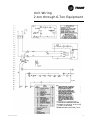
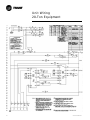
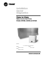
Installation
Owner
Diagnostics
Water-to-Water
Water-Source Heat Pump
Models WPWD, GSWD and EXWA
Models
“A” and later Design Sequence
WPWD
024-072 – 60 HZ
GSWD
024-072 – 60 HZ
EXWA
240 – 60 HZ
WSHP-SVX02A-EN
Notice
NOTICE:
Warnings and Cautions appear at appropriate sections throughout this manual.
Read these carefully.
WARNING
-Indicates a potentially hazardous situation which, if
not avoided, could result in death or serious injury.
CAUTION
-Indicates a potentially hazardous situation which, if
not
avoided, may result in minor or moderate injury. It
may also be used to alert against unsafe practices.
CAUTION
-Indicates a situation that may result in equipment or
property-damage-only accidents.
Important!
Equipment is shipped FOB (Free on
Board) at the manufacturer. Therefore,
freight claims for damages against the
carrier must be initiated by the receiver.
NOTICE:
Unit contains HCFC (R-22) Refrigerant
Instructions!
Section 608, Paragraph C of the 1990 Clean Air Act states:
Effective July 1, 1992, it shall be unlawful for any person, in course of
maintaining, servicing, repairing, or disposing of an air conditioning system, to
knowingly vent or release any CFC or HCFC refrigerant. Minimal releases (air
purges or refrigerant hoses) associated with good faith attempts to recapture or
recycle are exempt from the ban on venting.
Responsible Refrigerant Practices!
Trane believes that responsible refrigerant practices are important to the
environment, our customers, and the air conditioning industry. All technicians
who handle refrigerants must be certified. The Federal Clean Air Act (Section 608)
sets forth the requirements for handling, reclaiming, recovering and recycling of
certain refrigerants and the equipment that is used in these service procedures.
In addition, some states or municipalities may have additional requirements that
must also be adhered to for responsible management of refrigerants. Know the
applicable laws and follow them.
© 2002 American Standard Inc.
WSHP-SVX02A-EN
Contents
Installation/Startup/Commissioning
WSHP-SVX02A-EN
4
Pre-installation Checklist
4
General Information
5
Dimensions/Weights
6
Installation Instructions
10
Electrical Requirements
19
Pre-Startup Checklist
20
Startup/Commissioning
21
Sequence of Operation
21
Operating Pressures
22
Startup Checklist & Log
30
24
Maintenance
25
Warranty Information
26
Troubleshooting Checklist
28
Unit Wiring
29
3
Pre-installation
Checklist
WARNING
Fiberglass Wool!
Product contains fiberglass wool. Disturbing the insulation in this
product during installation, maintenance or repair will expose you to
airborne particles of glass wool fibers and ceramic fibers known to the
state of California to cause cancer through inhalation. Glass wool fibers
may also cause respiratory, skin or eye irritation.
Jobsite Inspection
Always perform the following checks before accepting a unit:
1. Verify that the nameplate data matches the data on the sales order and bill of
lading (including electrical data).
2. Verify that the power supply complies with the unit nameplate specifications.
3. Visually inspect the exterior of the unit, for signs of shipping damage. Do not
sign the bill of lading accepting the unit(s) until inspection has been completed. Check for damage promptly after the unit(s) are unloaded. Once the
bill of lading is signed at the jobsite, the unit(s) are now the property of the
SOLD TO party and future freight claims MAY NOT be accepted by the
freight company.
4. Verify that the refrigerant charge has been retained during shipment by use
of gauges. Schrader taps are located external to the cabinet on the 2-ton
through 6-ton equipment.
5. After assuring that charge has been retained, reinstall the schrader caps to
assure that refrigerant leakage does not occur.
WARNING
Microbial Growth!
Wet interior unit insulation can become an amplification site for
microbial growth (mold), which may cause odors and damage to the
equipment and building materials. If there is evidence of microbial
growth (mold) on the interior insulation, the insulation should be
removed and replaced prior to operating the system.
Jobsite Storage
This unit is intended for indoor use only. To protect the unit from damage due to
the elements, and to prevent possible IAQ contaminant sources from growing,
the unit should be stored indoors. If indoor storage is not possible, the following
provisions for outdoor storage must be met:
1. Place the unit(s) on a dry surface or raise above the ground to assure adequate air circulation beneath the unit.
2. Cover the unit(s) with a water proof tarp to protect them from the elements.
3. Make provisions for continuous venting of the covered units to prevent
moisture from standing on the unit(s) surfaces. Wet interior unit insulation
can become an amplification site for microbial growth (mold) which has
been determined to be a cause of odors and serious health related indoor air
quality problems.
4. Store units in the normal UP orientation to maintain oil in the compressor.
5. Do not stack more than three units in total height for the WPWD/GSWD 2-ton
through 6-ton configurations, and no more than two units high for the EXWA
20-ton configuration.
4
WSHP-SVX02A-EN
General
Information
Unit Nameplate
The unit nameplate is located at the
front of the unit. It includes the unit
model number, serial number, electrical characteristics, refrigerant charge,
and other pertinent unit data.
Compressor Nameplate
The nameplate for the compressors
are located on the compressor shell.
Unit Description
Before shipment, each unit is leak tested, dehydrated, charged with refrigerant and run tested for proper control
operation.
Water-to-Refrigerant Coils
The brazed-plate water-to-refrigerant
heat exchangers for the 2-ton through
6-ton equipment are constructed of
stainless steel.
The water-to-refrigerant heat exchangers for the 20-ton equipment are
an inner copper tube or cupro-nickel
(option available on the source-side
only) and steel tube (tube-within-atube) design.
Both heat exchanger types are leak
tested to assure there is no cross leakage between the water and refrigerant
gas.
Water Connections
One inch brass swivel connections are
provided for the 2-ton through 6-ton
equipment. Each brass fitting has a
one inch gasket for the connector. The
gaskets are shipped in the electrical
compartment to prevent loss at the job
site.
Water connections for the 20-ton are
located inside the unit at the units
front (source-side) and back (loadside). The fitting consist of a 2-inch female pipe threaded connection.
Controls
The control system offered to control
the unit is a Basic 24 volt control for
the 2-ton through 6-ton unit sizes, and
a deluxe 24 volt micro processing
board for the 20-ton unit.
All power wiring to the equipment is
made at the unit contactor for the 2WSHP-SVX02A-EN
ton through 6-ton equipment, and at
the power block for the 20-ton equipment.
All low voltage wiring is made at the
unit’s low voltage terminal board.
Wiring Connections
Troubleshooting and connection diagrams for the equipment may be located in the back of this manual.
Basic 24V Controls
(for 2-ton through 6-ton units)
Safety devices for equipment containing the basic 24V control option include a low pressure switch and a
freezestat to prevent compressor operation during low temperature activity. The switch is set to activate at
refrigerant pressures of 35 psig or 7
psig to fit most applications.
A high pressure switch prevents compressor operation during high or excessive discharge pressures
exceeding 395 psig.
The lockout relay communicates the
low or high pressure situation to the
compressor to prevent operation. The
relay may be reset at the thermostat,
or by cycling power to the unit.
(which may be available for field use).
See page 17 for diagnostic information.
Desuperheater
(Option for 2-ton through 6-ton units)
For units containing the desuperheater option, the unit is shipped from the
factory with a desuperheater water
coil and pump mounted internal to the
unit cabinetry. For domestic hot water
hook-up instructions, see manual
WSHPC-IN-4 or 72-9006-02.
The desuperheater pump fuse is located in the control box within a container. The fuse is not factory installed to
avoid possible pump damage at initial
start-up. If the fuse in installed and the
unit is started without water in the system, the pump will be damaged. See
page 17 for fuse installation.
Schrader Connections
Connections for the low and high side
of the refrigeration system are located
conveniently on the unit’s right side
for the 2-ton through 6-ton units, and
behind the front, refrigeration access
panel for the 20-ton unit.
General alarm may be accomplished
through the lockout relay to drive light
emitting diodes (LEDs) on a field supplied status indicating thermostat. Terminal 6 on the lockout relay is open for
field use in malfunction indications.
This feature will drive dry contacts
only, and cannot be used to drive field
installed control inputs.
Deluxe 24V Controls
(for 20-ton unit)
Units containing the Deluxe 24V control design will incorporate a microprocessor-based control board. The
Trane microprocessor board is factory
wired to a terminal strip to provide all
necessary terminals for field connection. The deluxe board is equipped
with a random start relay, anti-short
cycle timer, brown out protection,
compressor disable, unit safety control, diagnostics and a generic relay
5
Dimensions/Weights/
Clearance
Table 1: Unit weights
Size
Shipping
Weight
with pallet (lb)
Shipping
Weight
w/o pallet (lb)
024
163
153
036
183
173
042
203
193
048
214
204
060
244
234
072
277
267
240
1222
1156
WARNING
Improper Unit Lift!
Test lift unit approximately 24 inches to verify proper
center of gravity lift point. To avoid dropping of unit,
reposition lifting point if unit is not level. Failure to
properly lift unit could result in death or serious injury
or possible equipment or property-only damage.
Unit Location and Clearances
Locate the unit in an indoor area. The
ambient temperature surrounding the
unit must not be less than 45°F. Do
not locate the unit in areas subject to
freezing.
Attention should be given to service
clearance and technician safety. The
unit access panels may be easily removed. There must be enough space
for service personnel to perform maintenance or repair. Provide sufficient
room to make water, and electrical
connection(s). Local and national
codes should be followed in providing
electrical power connections. See Figure 1 for mechanical clearances.
Figure 1: Mechanical clearances
6
WSHP-SVX02A-EN
Dimensions
WPWD/GSWD 024-036
WSHP-SVX02A-EN
7
Dimensions
WPWD/GSWD 042-072
8
WSHP-SVX02A-EN
Dimensions
EXWA 240
WSHP-SVX02A-EN
9
Installation
General Installation Checks
The checklist below is a summary of
the steps required to successfully install a unit. This checklist is intended to
acquaint the installing personnel with
procedures required in the installation
process. It does not replace the detailed instructions called out in the applicable sections of this manual.
1
Remove packaging and inspect the
unit. Check the unit for shipping
damage and material shortage; file
a freight claim and notify appropriate sales representation.
Note: The units have been tied to
the skid by (4) angle brackets. Remove these brackets from the unit
to slide unit from skid.
2
Verify the correct model, options
and voltage from the unit nameplate.
3
Verify the installation location of
the unit will provide the required
clearance for proper operation.
4
Remove refrigeration access panel
and inspect the unit. Be certain the
refrigerant tubing has clearance
from adjacent parts.
WARNING
Hazardous
Voltage!
Disconnect all electric power,
including remote disconnects
before servicing. Follow proper
lockout/tagout procedures to
ensure the power can not be
inadvertently energized. Failure to
disconnect power before
servicing could result in death or
serious injury.
Main Electrical
5 Verify the power supply complies
with the unit nameplate specifications.
6
Inspect all control panel components; tighten any loose connections.
7
Connect properly sized and protected power supply wiring to a
field-supplied/installed disconnect
switch and to the main power terminal block (1TB1) in the unit control box for the 20-ton equipment,
or (1K1) for the 2-ton through 6ton equipment.
8
Install proper grounding wires to
an earth ground.
Note: All field-installed wiring must
comply with NEC and applicable local
codes.
Low Voltage Wiring (AC & DC)
Requirements
9 Connect properly sized control wiring to the proper termination
points between the field supplied
thermostat and the terminal strip
located in the equipment control
box.
10
WSHP-SVX02A-EN
Installation
WARNING
Improper Unit Lift!
Test lift unit approximately 24
inches to verify proper center of
gravity lift point. To avoid
dropping of unit, reposition lifting
point if unit is not level. Failure to
properly lift unit could result in
death or serious injury or possible
equipment or property-only
damage.
Unit Placement
Units may be placed into a field supplied mechanical rack (See Figure 2),
or placed on a finished floor. Loosen
compressor bolts to release tension of
the rubber grommets to help reduce
vibration during operation. Sound
proofing material (field supplied) is
recommended to help attenuate noise
generated by compressor vibration.
Figure 2: Racking installation
It is important to leave appropriate
clearances around the unit to achieve
maintenance and
serviceability to
the equipment.
See page 6 for
service clearance
dimensions.
Water Connection
Connect the source-side and load-side
water-in/water-out from the water-towater heat pump to the source system
and the load system.
Note: The source for a water-to-water
heat pump is typically a boiler/cooling
tower or geothermal loop.
The load for a water-to-water heat
pump is typically fresh-air unit(s), fan
coil(s), hydronic coil(s), radiant heat,
wall fin, or potable water.
The source and load connections for
the 2-ton through 6-ton equipment is
on the right hand side of the unit.
The 20-ton equipment incorporates
the source-side connection at the
unit’s front, and the load-side connection at the unit’s back.
For vibration isolation, it is recommended that flexible steel braided
hoses be installed instead of hard piping the equipment to the main loop
system or mechanical device.
Trane offers 4-types of hose kit variations:
•
Stainless steel braided flexible
hose with manual shut-off (ball)
valves
•
Stainless steel braided flexible
hose with manual deluxe shut-off
(ball) valves
•
Stainless steel braided flexible
hose with manual circuit-setter
valve
•
Stainless steel braided flexible
hose with automatic balancing
valve
Additional accessories, such as a
strainer are recommended for use to
eliminate contaminants from entering
the brazed-plate or co-axial water-torefrigerant heat exchangers.
Figure 3: Water connection
WSHP-SVX02A-EN
11
Installation
Cleaning and Flushing
the Water Loop
After the piping system is complete,
the flexible hose connectors should be
doubled back to complete the water
circuit external to the unit (avoiding
trash settle-out in the condenser). Figure 4. An extra pipe may be necessary
to connect the hose kits. See Page 14
for antifreeze/water mixture by volume.
(1) Water circulation system should be
filled with clean water using the water
make up connections. Note: Air vents
should be opened during filling.
(2) With the air vents closed, start the
circulating pump and then crack the air
vents to bleed off the trapped air, assuring circulation through all components of the system.
Note: Make up water must be available
to the system to replace the volume
formerly occupied by the air that is
Connecting a Loop Pump Kit
Closed Loop System
All piping external to the unit is the responsibility of the installer. The water
pipe installation must be done in accordance with local codes. If no local
code applies, national codes should be
followed. It is the contractor’s responsibility to know and adhere to all applicable codes.
Water inlet and outlet to the unit’s water-to-refrigerant heat exchanger are
clearly marked on the submittal drawings found on pages 7 through 9. The
supply and return piping must be installed correctly to the unit to ensure
the safety devices will work properly.
Units that are not piped accordingly
will not obtain the manufacturers warranty.
A pump module (Figure 5) and hose kit
(Figure 6) are typically used to connect
the unit to closed loop piping in domestic applications.
12
bled off.
(3) With the air vented and the water
circulating, the entire system
should be checked for leaks with repairs made as required.
(4) Operate the supplementary
heat system making checks per
manufacturer’s instructions. During this operation, visual checks
should be made for leaks that may
have occurred due to increased
heat. Repair as required.
Note: Vents should be open when the
pumps and supplementary heat system are shut down.
Figure 4: Flushing water loop
(5) Open the system at the lowest
point for the initial blow down
(making sure the make up water is
equal to the water being dumped).
Continue blow down until the water
leaving the drain runs clear, but not
less than 2 hours.
(6) Shut down pumps and supplementary heat system. Reconnect the hoses
placing the water-to-refrigerant heat
exchanger in the water circulating system.
FROM UNIT’S
W.O.
TO UNIT’S
W.I.
BRONZE OR CAST IRON PUMP
PURGING CAP (2)
SHUT-OFF 3-WAY
VALVE (2)
Figure 5 Pump module
1" MPT x BARB FITTINGS,
1" MPT x BARB ELBOWS with
PRESSURE TEMPERATURE PORTS,
AND 10’ OF RUBBER HOSE with
4 HOSE CLAMPS.
Figure 6: Hose kit
WSHP-SVX02A-EN
Installation
Supply/Return Pipe Connections
to the Loop Pump Kit
(1) Connect the supply and return hoses to the water-inlet (from supply) and
water-outlet (to return) of the unit. The
rubber gaskets for the water-in and
water-out connections are located in
the control box. These gaskets require
field installation prior to connecting
the water piping to the unit.
(2) Hand tighten the 1" FPT brass swivel quick connections to the 1" MPT
adapter with P/T ports. Using a
wrench, tighten the adapter approximately 1/2 additional turn. Care must
be taken to avoid overtightening as to
not dislodge the snap ring.
(3) The water lines should be routed
not to interfere with access to the unit.
The use of a short length of high pressure hose with the swivel fitting may
simplify the connections and prevent
vibration. Pressure/Temperature (P/T)
ports are required for troubleshooting
the hydronic side of the unit. Extreme
care should be taken by the installing
contractor to prevent dirt or other foreign matter from entering the pipes or
piping components during construction. Pipes should be capped until they
are in place and ready to be connected
to the system.
(4) Install the Trane loop pump module. See installation manual WSHPCIN-5 or 72-9006-03 for instructions. If
the unit does not contain a Trane loop
pump module, two ball valves must be
installed between the unit and the
loop’s water pump to isolate the unit
from the system’s water loop during
maintenance and emergency situations. See Figure 7.
If the unit s contain a Trane loop pump
module, shut-off valves are supplied
by the manufacturer within the pump
module assembly.
(5) Connect the unit’s water-in and water-out hose to the loop pump module.
(6) The pumps connect to the load side
230 volt compressor contactor, and require a field installed 6 amp in-line
fuse and holder.
Figure 7: Loop pump kit installation
WSHP-SVX02A-EN
(7) Insulate all indoor piping. Equipment is designed to operate with fluid
temperature of 25ºF to 120ºF
13
Installation
Water Heater Hook-up (option)
Instructions for connection from the
desuperheater (option) water-in/out to
the domestic hot water heater may be
found in WSHPC-IN-4 or 72-9006-02.
This water heater kit (Figure 8) ships in
all units with the desuperheater option. The kit is zip tied to the compressor base; and consists of piping
connections and shut-off valve.
Figure 8: Water heater kit
For units containing the desuperheater option, the desuperheater pump
fuse is located within a container inside of the control box. The fuse is not
factory installed.
Note: If the fuse is installed, and the
unit is started without water in the system, pump damage may occur.
Using Antifreeze
In areas of the country where entering
water temperatures drop below 45°F
or where piping is being run through
areas subject to freezing, the loop
must be freeze protected by using an
approved antifreeze solution to prevent the earth loop water from freezing inside the heat exchanger.
Methanol and glycols are the most
commonly used antifreeze solutions.
Consult your geothermal unit supplier
for locally approved solutions in your
area.
Propylene glycol is not recommended
in installations where the water temperature are expected to fall below
30°F. At extreme temperatures, the
viscosity increases to the point where
normal loop circulating pumps may
not maintain proper flow.
If propylene glycol is the only locally
approved solution for anti-freeze,
good engineering practices should be
used to achieve the desired flow.
Table 2: Antifreeze requirements based on volume
Type of Antifreeze
Minimum Temperature for Freeze Protection
10°F
15°F
20°F
25°F
30°F
Methanol
25%
21%
16%
10%
3%
Propylene Glycol
-
-
-
-
6%
Calculate the approximate volume of
water in the system by using the requirements detailed in Table 2. Add
three gallons to this total to allow for
the water contained in the hose kit and
geothermal unit.
14
WSHP-SVX02A-EN
Installation
Filling the Loop Pump Kit System
Once the loop, pump module and unit
are fully connected, the system will
need to be filled with water or water/
antifreeze solution. See Page 14 for antifreeze/water mixture by volume.
Fill both sides of the outside portion of
the loop first via the pump module.
The hose kit and unit should be filled
last after purging of the ground loop is
complete.
To fill the outside loop; (1) attach a
water hose to the 1-inch FPT brass
valve ports located on the front of the
pump module (the caps at the front of
the module should be removed). (2)
Rotate both valve 1 and valve 2 to the
"Position B" to prevent water from going to the unit. (3) Turn on the water
and allow the earth loop to slowly fill
with water. (4) Run the water until a
steady flow of water without air bubbles is observed coming out of the discharge hose.
Filling the Hose Kit and Unit and/or
Hose Kit and Unit Flush
Filling the Outside Loop and/or
Outside Loop Flush
Run System
Full System Flush
To fill the hose kit and unit; (1) Reposition valve 1 to the "Position A" to
fill the unit and hose kit. (2) Turn the
water on and allow the hose kit and
unit to be filled slowly with water. (3)
Run the water until a steady flow of
water without air bubbles is observed
coming out of the discharge hose.
System Pressurization
(1) Rotate both valves 1 and 2 to the
"Position D" to pressurize the system.
(2) Examine all internal unit fittings or
connections for leaks. (3) After checking for leaks, the system is ready to be
flushed.
Note: There may be a certain amount
of entrained air left in the loop system.
Cleaning and Flushing
the Water Loop
All installations must be thoroughly
flushed to remove air and dirt from the
earth loop before running the system.
The pumps used in the pump module
are not adequate to use for the flushing out of the unit. A secondary pump
capable of delivering 50 gpm at 60 feet
of head (a 1 1/2 hp or larger pump) is
WSHP-SVX02A-EN
normally suitable for jobs up to six
tons. The loop must be flushed with a
high volume of water at a minimum
velocity of (2 feet per second) in both
directions. See Table 3 for flow rates
required to flush earth loops.
Table 3: System flushing flow rates
Pipe
Gallons per
100 Ft.
Minimum
Flush GPM
3/4" PE
3.02
3.8
6.0
1" PE
4.73
1 1/4" PE
7.55
9.5
1 1/2" PE
9.93
13.0
2" PE
15.36
21.0
Note: The plastic 1-inch MPT valve
plugs must be replaced after filling
and/or flushing is completed.
See "Position C" for valve rotation to
place the valves in RUN position.
15
Installation
Power Wiring
Field Installed Power Wiring
Power wiring to the equipment must
conform to National and Local Electric
Codes (NEC) by a professional electrician.
WARNING
Live Electrical
Components!
During installation, testing, servicing and troubleshooting of this
product, it may be necessary to
work with live electrical components. Have a qualified licensed
electrician or other individual
who has been properly trained in
handling live electrical components perform these tasks. Failure
to follow all electrical safety precautions when exposed to live
electrical components could result in death or serious injury.
Verify that the power supply available
is compatible with the unit’s nameplate. Use only copper conductors to
connect the power supply to the unit.
CAUTION
Use Copper
Conductors Only!
Unit terminals are not designed
to accept other types of conductors. Failure to use copper conductors may result in equipment
damage.
The high voltage connection is made
at the 1TB1 terminal block for the 20ton equipment, and at 1K1 for the 2ton through 6-ton equipment. The terminal block or contactor is located inside the unit control box. Refer to the
customer connection diagram that is
shipped with the unit for specific termination points.
Provide proper grounding for the unit
in accordance with the local and national codes.
Control Power Transformer
The 24-volt control power transformers are to be used only with the accessories called out in this manual.
Transformers rated greater than 50 VA
are equipped with internal circuit
breakers. If a circuit breaker trips, turn
OFF all power to the unit before attempting to reset it.
WARNING
Hazardous Voltage!
Disconnect all electric power, including remote disconnects before servicing. Follow proper
lockout/tagout procedures to ensure the power can not be inadvertently energized. Failure to
disconnect power before servicing could result in death or serious injury.
The transformer is located in the
control box.
Main Unit Power Wiring
A field supplied disconnect switch
must be installed at or near the unit in
accordance with the National Electric
Code (NEC latest edition).
Location of the applicable electric service entrance for HIGH (line voltage)
may be found on the unit submittal at
the front of this manual (pages 7
through 9).
16
WSHP-SVX02A-EN
Installation
Low Voltage Wiring
Controls Using 24 VAC
Before installing any wire, refer to the
electrical access locations on the unit
submittals located on pages 7 through
9.
Ensure that the AC control wiring between the controls and the unit’s termination point does not exceed three
(3) ohms/conductor for the length of
the run.
Note: Resistance in excess of 3-ohms
per conductor may cause component
failure due to insufficient AC voltage
supply.
Figure 9: Low voltage connection
Check all loads and conductors for
grounds, shorts, and mis-wiring.
Use copper conductors unless otherwise specified.
Do not run the AC low voltage wiring
in the same conduit with the high voltage power wiring.
Table 4: 24V AC conductors
Distance
from unit to Control
Recommended
Wire Size
000-460 feet
18 gauge
461-732 feet
16 gauge
733-1000 feet
14 gauge
Low voltage connection diagrams are
shown in Figure 9. Optional desuperheater fuse installation shown in Figure 10.
Figure 10: Desuperheater fuse installation
Table 5: Deluxe controller diagnostic LEDs
Color: Green
Color: Red
Controller Mode
LED1
LED2
LED3
OFF
OFF
OFF
Control OFF
ON
OFF
OFF
Normal/Compressor OFF
ON
OFF
FLASH
ON
OFF
ON
Normal/Compressor ON
FLASH
ON
OFF
Brownout Condition
ON
FLASH
ON
Soft Lockout (low pressure)
ON
FLASH
FLASH
Soft Lockout (high pressure)
ON
ON
ON
Manual Lockout (low pressure)
Manual Lockout (high pressure)
Anti-short Cycle
ON
ON
FLASH
ON
FLASH
OFF
Manual Lockout (condensate overflow)
ON
ON
OFF
Compressor Disable
WSHP-SVX02A-EN
17
Installation
Changing Freezestat or Low Pressure Cutout Switches
(WPWD/GSWD models ONLY)
Each unit has two factory installed low
pressure cutout switches and one
freezestat. Only one of the low pressure cutout switches is connected to
the 24 volt control circuit, dependent
on which freezestat is being used (i.e.
35°F or 20°F). Both the freezestat and
the low pressure cutout are in the lockout relay circuit. The freezestat monitors the temperature of the water
leaving the source and load side water-to-refrigerant heat exchangers,
protecting the heat exchanger from
fluid freeze up. The low pressure cutout monitors the suction pressure of
the compressor to protect the compressor from liquid floodback or operating under loss of charge conditions.
Units can be ordered from the factory
with either the 35°F or 20°F freezestat
option. The 20°F freezestat is ONLY
used on closed loop systems with antifreeze solution. The 35°F freezestat is
used on all other systems. The type of
freezestat on a unit can be determined
from the appropriate digit in the model
number. Digit 11 and/or 12 with a selection of 1 is a 35°F freezestat, whereas selection 2 is a 20°F freezestat.
What Freezestat Should Be
Applied?
As previously mentioned, every unit is
shipped from the factory with two low
pressure cutouts installed in the refrigerant circuit. One of the low pressure
cutouts disables the compressor at 35
psig, while the other disables the compressor at 7 psig. The 35 psig cutout is
used with the 35°F freezestat, while
the 7 psig cutout is used with the 20°F
freezestat.
Occasionally it will be necessary to
change the freezestat in the field. Examples of when this change-out is
necessary include:
(1) A unit with a 35°F freezestat is going to be put on a closed loop system
with antifreeze. By definition, the unit
requires a 20°F freezestat.
18
(2) A unit with a 20°F freezestat is going to be put on an open well system
or a closed loop system with NO antifreeze solution. By definition, the unit
must have a 35°F freezestat installed
prior to operation.
The best time to install the freezestat/
low pressure cutout is prior to installing the unit. The freezestat is easily accessible from the top service door.
WARNING
Hazardous Voltage!
Disconnect all electric power, including remote disconnects before servicing. Follow proper
lockout/tagout procedures to ensure the power can not be inadvertently energized. Failure to
disconnect power before servicing could result in death or serious injury.
Changing a Freezestat and Low
Pressure Cutout
The freezestat is located in the top of
the source-side water-to-refrigerant
heat exchanger leaving water line. The
freezestat is located in the twelve
o’clock position. The capillary tube is
inserted into the well approximately 8inches. Remove the existing freezestat
and replace it with the new freezestat.
the old low pressure cutout to the new
low pressure cutout.
Identifying the Low Pressure Cutouts
The 7 psig low pressure cutout is used
with a 20°F freezestat. It is installed in
the insulated line and is in the piping
tee going to the external schrader port.
The 35 psig low pressure cutout is
used with a 35°F freezestat. It is installed in the insulated line and is not
connected to any fittings.
The 395 psig high press cutout is installed in the un-insulated compressor
discharge line. It is the only cutout located in this line. Further, it is connected to an external schrader port.
If the low pressure cutout is not
changed when the freezestat is
changed, problems will occur. If the 35
psig low pressure cutout is connected
to a 20°F freezestat, the unit will go out
repeatedly on the low pressure cutout.
If the 7 psig low pressure cutout is
used with the 35°F freezestat, no problems will occur as long as the freezestat is operating normally. However,
if the freezestat does fail, the loop water could freeze before the suction
pressure dropped low enough for the
7 psig cutout to take the unit off the
line. Also, in a loss of charge situation,
the heat exchanger would freeze before the freezestat could take the unit
off-line.
Note: The wires must be moved from
one low
pressure
cutout to
the other.
The low pressure cutouts are located in
the insulated refrigerant
lines. The high
pressure cutout is located in the un-insulated
compressor discharge line and is the
only pressure cutout located
in this line. Change the wires from
Figure 11: Pressure switch location
WSHP-SVX02A-EN
Electrical
Requirements
Table E-1: Electrical performance WPWD/EXWA
Model/MBH
WPWD024
WPWD036
WPWD042
WPWD048
WPWD060
WPWD072
EXWA180
EXWA240
VOLTS-AC/HZ/PH
Min.
Util.
Volt
Max
Util.
Volt
Compressor
Each
RLA
LRA
No.
of
Comp
208-230/60/1
220-240/50/1
265/60/1
208-230/60/1
197
198
239
197
253
264
292
253
11.4
9.6
9.6
15.0
56.0
47.0
47.0
73.0
1
1
1
1
208-230/60/3
220-240/50/1
265/60/1
380-415/50/3
460/60/3
208-230/60/1
208-230/60/3
220-240/50/1
265/60/1
380-415/50/3
460/60/3
208-230/60/1
208-230/60/3
380-415/50/3
460/60/3
208-230/60/1
208-230/60/3
380-415/50/3
197
198
239
342
414
197
197
198
239
342
414
197
197
342
414
197
197
342
253
264
292
456
506
253
253
264
292
456
506
253
253
456
506
253
253
456
10.7
14.3
14.3
5.0
5.0
18.4
11.4
16.4
16.4
5.7
5.7
20.4
13.9
7.1
7.1
28.0
20.0
7.5
63.0
71.0
71.0
31.0
31.0
95.0
77.0
83.0
83.0
39.0
39.0
109.0
88.0
44.0
44.0
169.0
123.0
49.5
460/60/3
575/60/3
208-230/60/1
208-230/60/3
380-415/50/3
460/60/3
575/60/3
380-415/50/3
208/60/3
230/60/3
460/60/3
575/60/3
414
517
197
197
342
414
517
342
197
207
414
518
506
633
253
253
456
506
633
456
229
253
506
633
7.5
6.4
32.1
19.3
10.0
10.0
7.8
16.7
31.7
31.7
14.1
11.2
49.5
40.0
169.0
137.0
62.0
62.0
50.0
133.0
232.0
261.0
112.0
92.0
Without Desup
MCA
With Desup
Desup
RLA
0.4
0.4
0.4
0.4
MCA
14.3
12.0
12.0
18.8
Max
Fuse
25
20
20
30
14.7
12.4
12.4
19.2
Max
Fuse
25
20
20
30
1
1
1
1
1
1
1
1
1
1
1
1
1
1
1
1
1
1
13.4
17.9
17.9
6.3
6.3
23.0
14.3
20.5
20.5
7.1
7.1
25.5
17.4
8.9
8.9
35.0
25.0
9.4
20
30
30
15.0
15
40
25
35
35
15.0
15
45
30
15.0
15
60
45
15.0
0.4
0.4
0.4
0.4
0.4
0.4
0.4
0.4
0.4
0.4
0.4
0.4
0.4
0.4
0.4
0.4
0.4
0.4
13.8
18.3
18.3
6.7
6.7
23.4
14.7
20.9
20.9
7.5
7.5
25.9
17.8
9.3
9.3
35.4
25.4
9.8
20
30
30
15.0
15
40
25
35
35
15.0
15
45
30
15.0
15
60
45
15.0
1
1
1
1
1
1
1
2
2
2
2
2
9.4
8.0
40.1
24.1
12.5
12.5
9.8
37.58
71.39
71.39
31.73
25.24
15
15
70
40
20.0
20
15
50
100
100
45
35
0.4
0.4
0.4
0.4
0.4
0.4
0.4
------
9.8
8.4
40.5
24.5
12.9
12.9
10.2
------
15
15
70
40
20.0
20
15
------
Table E-2: Electrical performance GSWD
Model/MBH
GSWD024
GSWD036
GSWD042
GSWD048
GSWD060
GSWD072
WSHP-SVX02A-EN
VOLTS-AC/HZ/PH
208-230/60/1
208-230/60/1
208-230/60/1
208-230/60/1
208-230/60/1
208-230/60/1
Min.
Util.
Volt
Max
Util.
Volt
197
197
197
197
197
197
253
253
253
253
253
253
Compressor
Data
RLA
11.4
15.0
18.4
20.4
28.0
32.1
LRA
56.0
73.0
95.0
109.0
169.0
169.0
No.
of
Comp
Aux
Pump
Amps
1
1
1
1
1
1
2.5
2.5
2.5
2.5
2.5
2.5
Desup
Pump
RLA
0.4
0.4
0.4
0.4
0.4
0.4
MCA
17.2
21.7
25.9
28.4
37.9
43.0
Max
Fuse
25
35
40
45
60
70
19
Pre-Start
Checklist
Pre-Start-up Checklist
Before energizing the unit, the following system devices must be checked:
____ Is the high voltage power supply correct and in accordance with the nameplate ratings?
____ Is the field wiring and circuit protection the correct size?
____ Is the low voltage control circuit wiring correct per the unit wiring diagram?
____ Is the piping system clean/complete and correct? (A recommendation of all system flushing of debris from the waterto-refrigerant heat exchanger, along with air purging from the water-to-refrigerant heat exchanger be done in accordance with the Closed-Loop/Ground Source Heat Pump Systems Installation Guide).
____ Is vibration isolation provided? (i.e. unit isolation pad, hosekits)
____ Is unit serviceable? (See clearance specifications on page 6).
____ Are the low/high-side pressure temperature caps secure and in place?
____ Are all the unit access panels secure and in place?
____ Is the thermostat in the OFF position?
____ Is the water flow established and circulating through all the units?
____ Is the zone sensor correctly wired and in a good location?
____ Has all work been done in accordance with applicable local and national codes?
____ Has heat transfer fluid been added in the proper mix to prevent freezing in closed system application?
20
WSHP-SVX02A-EN
Sequence
of Operation
Initial Unit Start-up
Start-up with the system controls is included below: Note: Air Handlers should not be operated in the construction phase of dry
walling. The air-to-refrigerant coil will foul, and the warranty will be void.
1.Set the system control to the desired mode of operation.
2.Set the control switch to fans and circulation pumps. The compressor should NOT run.
3.Reduce the temperature control setting until the compressor, reversing valve, solenoid valve, and loop pump are
energized. Adjust water flow utilizing pressure/temperature plugs and comparing to tables contained in specification
sheet data. Water leaving the heat exchanger should be warmer than the entering water temperature (approximately
9°F-12°F); compressor amps should be within data plate ratings; the suction line should be cool with no frost
observed in the refrigerant circuit.
4.Check the cooling refrigerant pressures against values in Table OP1. (Page 22).
5.Turn the system control switch to the OFF position. Unit should stop running and the reversing valve should de-energize.
6.Leave unit off for approximately FIVE minutes to allow for pressure equalization.
7.Turn the thermostat to the lowest setting.
8.Set the thermostat system switch to the opposite mode of operation.
9.Adjust the temperature setting upward until the unit is energized. A water temperature decrease of approximately 5°F9°F leaving the heat exchanger should be noted. The compressor operation should be smooth with no frost observed
in the refrigeration circuit.
10.Check the heating refrigerant pressures against values in Table OP1. (Page 22)
11.Set the system control to maintain the desired space temperature.
12.Instruct the owner on system operation.
WSHP-SVX02A-EN
21
Operating Pressures
Operating Pressures
Table OP-1: Cooling mode operating pressures
Unit Size
EXWA 240
EXWA 240
Entering
Load
(Degree F)
53.6
86
50
Suction
Pressure
46-56
61-71
Entering Source Temperature (Degree F)
86
104
Discharge
Suction
Discharge
Suction
Discharge
Pressure
Pressure
Pressure
Pressure
Pressure
103-143
49-59
188-228
49-59
238-278
111-151
84-94
205-245
87-97
259-299
Table OP-2: Heating mode operating pressures
Unit Size
Entering
Entering Source Temperature (Degree F)
Load
50
68
104
(Degree F)
Suction
Discharge
Suction
Discharge
Suction
Discharge
Pressure
Pressure
Pressure
Pressure
Pressure
Pressure
EXWA 240
75
46-56
160-200
65-75
170-210
86-96
183-223
EXWA 240
104
49-59
245-285
68-78
254-294
94-107
268-308
EXWA 240
122
49-59
310-350
68-78
320-360
95-105
333-373
22
WSHP-SVX02A-EN
Operating Pressures
Water Pressure Drop
Tables 6 and 7 should be used to define feet of head/pressure drop. Note: To calculate feet of head, when using gauges that read in PSIG,
multiply PSI by 2.31.
Table 6: Cooling water pressure drops (WPD) in feet of head
Unit Size
024
036
042
048
060
072
240
GPM
3.8
7.0
8.9
4.6
8.5
10.8
5.2
9.5
12.1
6.0
11.0
14.0
7.6
14.0
17.8
8.7
16.0
20.4
30.0
55.0
70.0
Source
EWT
Ft. Head
F
Pressure
1.3
80
4.5
7.2
1.9
80
6.6
10.6
2.4
80
8.6
14.1
3.3
80
11.6
19.1
5.4
80
19.1
31.5
7.1
80
25.3
41.8
2.9
80
8.1
12.2
EWT
F
53.6
53.6
53.6
53.6
53.6
53.6
53.6
Load
Ft. Head
Pressure
1.6
5.4
8.7
2.3
7.9
12.7
3.0
10.3
17.1
4.0
14.0
23.1
6.5
23.1
38.1
8.6
30.5
50.5
3.6
9.7
14.7
Table 7: Heating water pressure drops (WPD) in feet of head
Unit Size
024
036
042
048
060
072
240
GPM
3.8
7.0
8.9
4.6
8.5
10.8
5.2
9.5
12.1
6.0
11.0
14.0
7.6
14.0
17.8
8.7
16.0
20.4
30.0
55.0
70.0
Source
EWT
Ft. Head
F
Pressure
1.5
60
5.1
8.3
2.2
60
7.6
12.2
2.8
60
9.8
16.2
3.8
60
13.3
21.9
6.2
60
21.9
36.1
8.2
60
28.9
47.9
3.4
60
9.2
13.9
EWT
F
80
80
80
80
80
80
80
Load
Ft. Head
Pressure
1.3
4.5
7.2
1.9
6.6
10.6
2.4
8.6
14.1
3.3
11.6
19.1
5.4
19.1
31.5
7.1
25.3
41.8
2.9
8.1
12.2
Water Volume
Table 8 is provided for use in calculating glycol requirements for the unit.
Table 8: Water volume
Unit Size
024
036
042
048
060
072
240
Water Side
Volume
Cubic In.
55
105
105
259
259
259
1057
Water Side
Volume
Cubic Ft.
0.032
0.061
0.061
0.150
0.150
0.150
0.615
Water Side
Volume
Gallons
0.238
0.455
0.455
1.121
1.121
1.121
4.576
Note: The EXWA 240 has two circuits.
Flow Checks
For the operating temperature drop (heating) and rise (cooling), refer to Table OP1 and OP2 for the proper water temperature change. Depending on the unit size, entering water temperature and water flow rate, the cooling temperature rise is
from 8°F-16°F. Based on the same criteria for heating, the temperature drop is from 2°F-13°F.
Pressure
Using the P/T ports and one 0-60 psi pressure gauge with the P/T port adapter, measure the pressure difference between
the water-in and water-out connections. Compare the pressure differential to Table 6 to determine flow.
Start-up Checklist and Log
Use the form on page 24 to log system and unit temperatures during start-up.
WSHP-SVX02A-EN
23
Start-up Checklist
and Log
Installing Contractor: Use this form to thoroughly check-out the system and units before and during
start-up. (This form need not be returned to the factory unless requested during technical service support).
Job Name:
Model Number:
Date:
Serial Number:
In order to minimize troubleshooting and costly system failures, complete the following checks and data
entries before the system is put into full operation.
MODE
Entering fluid temperature
Source
F
Leaving fluid temperature
Temperature differential
Water coil heat exchanger
(Water Pressure IN)
Water coil heat exchanger
(Water Pressure OUT)
Pressure Differential
HEAT
Load
COOL
Load
F
Source
F
F
F
F
F
F
F
F
F
F
PSIG
PSIG
PSIG
PSIG
PSIG
PSIG
PSIG
PSIG
PSIG
PSIG
PSIG
PSIG
COMPRESSOR
Amps
Volts
Discharge line temperature
(after 10 minutes)
24
F
F
F
F
WSHP-SVX02A-EN
Maintenance
Preventive Maintenance
Maintenance on the unit is simplified
with the following preventive suggestions:
WARNING
Hazardous
Voltage!
Disconnect all electric power, including remote disconnects before servicing. Follow proper
lockout/tagout procedures to ensure the power can not be inadvertently energized. Failure to
disconnect power before servicing could result in death or serious injury.
Check the contactors and relays within
the control panel at least once a year.
It is good practice to check the tightness of the various wiring connections
within the control panel.
WSHP-SVX02A-EN
WARNING
Hazardous
Chemicals!
Coil cleaning agents can be either
acidic or highly alkaline. Handle
chemical carefully. Proper handling should include goggles or
face shield, chemical resistant
gloves, boots, apron or suit as required. For personal safety, refer
to the cleaning agent manufacturers Materials Safety Data Sheet
and follow all recommended safe
handling practices. Failure to follow all safety instructions could
result in death or serious injury.
It should be noted that the water quality should be checked periodically. See
Table 9.
Table 9: Water Quality Table
Scaling
Calcium and magnesium
(total hardness)
A strainer (60 mesh or greater) must
be used on an open loop system to
keep debris from entering the unit heat
exchanger and to ensure a clean system.
Corrosion
For units on well water, it is important
to check the cleanliness of the waterto-refrigerant heat exchanger. Should
it become contaminated with dirt and
scaling as a result of bad water, the
heat exchanger will have to be back
flushed and cleaned with a chemical
that will remove the scale. This service
should be performed by an experienced service person.
Less than 350 ppm
pH
7-9.5
Hydrogen Sulfide
Less than 1 ppm
Sulfates
Less than 25 ppm
Chlorides
Less than 125 ppm
Carbon Dioxide
Less than 75 ppm
Total dissolved solids
(TDS)
Less than 1000 ppm
Biological Growth
Iron Bacteria
Low
Erosion
Suspended Solids
Low
25
Warranty
Information
Warranty Information
Standard Warranty
The standard water-source heat pump warranty is Trane’s parts-only warranty, running 12-months from startup, not to exceed 18-months from shipment.
Extended Warranty
The optional extended warranty is a second through fifth year warranty. The time starts at the end of standard
1-year coverage through the fifth year.
These extended warranties apply only to new equipment installed in domestic Trane Commercial Systems
Group sales territories and must be ordered prior to start-up.
26
WSHP-SVX02A-EN
Troubleshooting
WARNING
Hazardous Service
Procedures!
The maintenance and trouble
shooting procedures recommended in this section of the manual
could result in exposure to electrical, mechanical or other potential
safety hazards. Always refer to
the safety warnings provided
throughout this manual concerning these procedures. When possible, disconnect all electrical
power including remote disconnects before servicing. Follow
proper lockout/tagout procedures
to ensure the power can not be inadvertently energized. When necessary to work with live electrical
components, have a qualified licensed electrician or other individual who has been trained in
handling live electrical components per these tasks. Failure to
follow all of the recommended
safety warnings provided, could
result in death or serious injury.
Preliminary Trouble Inspection
If operational difficulties are encountered, be sure to perform the preliminary checks before referring to the
troubleshooting chart on page 28.
• Verify that the unit is receiving electric supply power.
• Ensure that the fuses in the fused
disconnect are intact.
General Operation
The standard model is designed for indoor installation. When the unit is installed in an unconditioned space, the
unit may not start in cool weather (approximately 45°F). It may then be necessary to start the unit in the cooling
mode for three to five minutes. The
unit may then be shut-off (there will be
a two minute time-out of the unit), and
restarted in the heating mode. The
freeze protection thermostat should
also be checked as it may be adversely
affected by ambient temperature.
Like any other type of mechanical
equipment, the unit performs best
when it is well maintained.
Operation with a Conventional
Thermostat
The unit is equipped with safety controls, including high pressure control,
low pressure control and a freeze protection thermostat, set to shut off the
compressor under abnormal temperature or pressure conditions. If the safeties shut off the compressor, a lockout
relay prevents short cycling from the
abnormal condition. When conditions
are corrected, the lockout control can
be reset by setting the thermostat system switch to OFF wait a few minutes
for the system pressure to equalize,
and then return to HEAT or COOL. If
the condition continues, an authorized
service person should check out the
unit.
After completing the preliminary
checks, inspect the unit for other obvious problems such as leaking connection, broken or disconnected wires,
etc. If everything appears to be in order, but the unit still fails to operate
properly, refer to the troubleshooting
chart on page 28.
WSHP-SVX02A-EN
27
Troubleshooting
Checklist
Problem
No response to any
thermostat setting
Unit short cycles
Insufficient capacity
Heating
X
X
X
X
X
X
Cooling
X
X
X
X
X
X
High head pressure
Low suction pressure
Low Pressure switch open
X
Low on refrigerant charge
X
X
X
X
X
X
X
X
X
X
X
X
X
X
X
Restricted thermal expansion valve
Defective reversing valve
Thermostat improperly located
Unit undersized
Inadequate water flow
Scaling in heat exchanger
Water too hot
Water too cold
Inadequate GPM
Water too hot
Overcharged with refrigerant
Defective pressure switch
Trash in heat exchanger
Low water flow
Overcharge of refrigerant
Non-condensable in system
Water too hot
Undercharged
Restricted thermal expansion valve
Inadequate GPM
Inadequate GPM
Water too cold
Undercharged with refrigerant
Defective pressure switch
Replace
See WSHP-IOM-# for touch test chart
Relocate
Recalculate heat gains/losses
Increase GPM
Clean or replace
Decrease temperature
Increase temperature
Increase water flow to unit
Decrease temperature
Decrease charge
Check or replace
Backflush
Increase GPM
Decrease charge
Evacuate and recharge by weight
Decrease temperature
Locate leak, repair and recharge
Repair / replace
Increase GPM
Increase GPM
Increase temperature
Increase charge
Replace
X
Heat transfer fluid too cold
Raise water temperature. For smaller
tonnage units, switch pressure switch
wires from 35 psig to 7 psig
Inadequate GPM
Increase GPM
X
X
X
X
X
X
X
X
X
X
X
X
X
X
X
X
X
X
X
X
X
X
X
X
X
X
Freezestat open
X
X
28
Correction
Check fuses
Replace
Repair
Replace
Reset Transformer
Relocate
Locate leak, repair and recharge by
weight (not by superheat)
X
X
High pressure switch open
Cause
Main power off
Defective control transformer
Broken or loose connection
Defective thermostat
Transformer
Thermostat or sensor improperly located
X
Water too cold
Increase GPM
Defective freezestat
Replace freezestat
Heat transfer fluid too cold
Replace freezestat. For smaller tonnage
units, switch pressure wires from 35 psig
to 7 psig.
WSHP-SVX02A-EN
Unit Wiring
2-ton through 6-Ton Equipment
WSHP-SVX02A-EN
29
Unit Wiring
20-Ton Equipment
30
WSHP-SVX02A-EN
Trane
An American Standard Company
www.trane.com
For more information, contact
your local district office or e-mail us at
[email protected]
Literature Order Number
WSHP-SVX02A-EN
File Number
SV-UN-WSHP-SVX02A-8-02
Supersedes
WSHPC-IOM-4 and 72-9036-02
Stocking Location
Inland
Since Trane has a policy of continuous product and data improvement and reserves the right to change
design and specifications without notice.