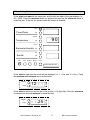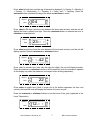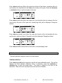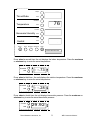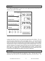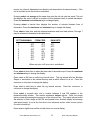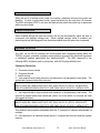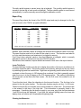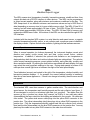
1
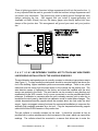
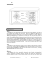
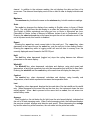
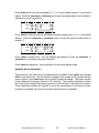
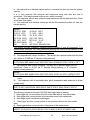
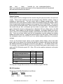
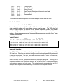
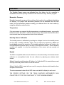
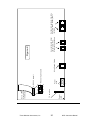
WRL
Weather Report Logger
The WRL senses wind, temperature, humidity, barometric pressure, rainfall and time, then
outputs this data via a RS-232 interface to other devices. The WRL can be programmed
to output current weather, along with minimum and maximum conditions for the day. The
WRL keeps track of two different minimum and maximum values and up to 8000 lines of
data (depending on memory size) in its non-volatile memory clock. The WRL-10 has 2K of
memory and will retain approximately 30 lines of data. The WRL-32 has 32K of memory
and will retain approxomately 2000 lines of data. The WRL-128 has 128K of memory and
retains about 8000 lines of data. All functions of the WRL can be controlled through its RS232 interface.
Included with the standard WRL system is a wind direction and speed sensor, a pagoda
mounted temperature/humidity sensor, a rain collector and a pressure sensor installed in
the display console. Options include solar radiation, lightning and leaf wettness sensors.
Normal Operation
When in normal operation (no buttons depressed) the instrument displays current wind
direction and speed, cycles current time and date, cycles current indoor, outdoor
temperature. In addition, if selected, the optional solar radiation or aux temperature is
displayed when both the indoor and outdoor indicator lights are extinguished. The unit also
cycles current barometric pressure, current relative humidity, and cycles daily, monthly and
term cumulative rainfall. By utilizing the hold buttons associated with each display, the user
may select the most important readings to the user. During wind speeds in excess of 99
miles per hour a small light turns on between the digits of the wind speed display.
Trend indicators (arrows) are located to the right of the temperature, relative humidity, and
barometric pressure displays. If, for example, the current relative humidity is increasing
then the up trend arrow appears on. If there is no change in humidity, then the arrow would
not appear.
Installation
The standard WRL uses three sensors to gather weather data. The wind direction and
speed sensor, the temperature and humidity pagoda and the rain collector (see figure 1).
All are designed to mount to a television type mast (not provided). The cables from the
sensors go into a junction box, where they connect via RJ45’s to two multi-wire cables
(intermediates) that are routed into the building and attached to the console. All cables are
color-coded. The yellow wind sensor cable plugs into the yellow RJ45 connector in the
junction box. The yellow intermediate (wind) also plugs into a yellow RJ45 connector in the
junction box. Plug the temperature/humidity pagoda and the rain collector (both colored
blue) and the blue intermediate into the blue RJ45 connectors in the junction box. You may
place any blue cable into any blue RJ45 connector, the order does not matter.
Texas Weather Instruments, Inc.
1
WRL Instruction Manual
There is lightning protection (transient voltage suppressers) built into the junction box. It
is very important that the mast is grounded or else the transient voltage suppressers will
not protect your instrument. The junction box picks up earth ground through the hose
clamps mounting the box. We suggest that you install a copper-grounding rod
(available at Radio Shack) and run the heavy gauge wire directly behind the hose
clamps of the junction box. This arrangement will ground your mast and your junction
box.
C A U T I O N !! :BE EXTREMELY CAREFUL NOT TO TOUCH ANY HIGH POWER
LINES DURING INSTALLATION OF THE VARIOUS SENSORS!!!
The wind direction and speed sensor is normally mounted on television type antenna masts
(see Figure 1). For best results the wind sensor should be mounted twenty feet above the
roof of the building. Higher installation yelds more accurate readings. There is one yellow
cable that must be strung from the wind sensor to the console via the junction box. The
wind direction sensor is calibrated at the factory and should be installed with the wind
sensor arm pointed to the North. The wind sensor can be mounted in any direction and
recalibrated via the WRL console, but it is more convenient to use the precalibrated North
reference. If calibration is necessary after the unit is already mounted, pick a calm day or
immobilize the wind vane by hand and use calibraton mode to make these changes. The
outside temperature/humidity pagoda should be mounted about two feet under the wind
sensor. Again, we suggest a twenty-foot mast for commercial installations to overcome the
artificially high readings generated by a hot roof. Plug the temperature/humidity pagoda
cable into the blue RJ45 connector in the junction box.
The rain collector is normally mounted on the mast. It should be mounted as low as
possible both to reduce windage and to limit movement of the mast, which can cause false
readings. The collector should be mounted in a manner that allows rain to enter the
Texas Weather Instruments, Inc.
2
WRL Instruction Manual
collector unencumbered by surrounding obstacles. Use a bubble level to make sure that
the collector is perfectly level with the ground. Failure to level the collector will cause
inaccurate rainfall readings. The rain collector has one blue cable, which must be
connected to the console via the junction box.
Mount the junction box under the rain collector using the hose clamps that are installed on
the box (see figure 1)and remove the front cover of the junction box. Next insert the
connectors from the sensors and the cables from the console through the hole in the bottom
of the junction box and then out the front of the box. Plug all the yellow connectors into the
yellow RJ45 connectors and all the blue connectors into the blue RJ-45 connectors and
then pull the excess cable out of the junction box (j-box). Be sure and replace the rubber
gasket on the junction box so that it can remain watertight.
Plug the yellow intermediate cable (wind) into the yellow pigtail exiting the back of the
console. Do the same for the blue cable (temp/humidity & rain). Next, plug in the serial
cable into the connector in the rear of the console and the proper serial port of your
computer. If you are supplying your own serial cable, be sure that either you have a null
modem adapter attached to the cable or that the cable is a null modem cable. The cable
supplied with the WRL will have four connectors or will be marked with a green
color on one of the cable connectors. Plug the wall transformer into a 120V wall socket
to power up the unit.
The optional solar sensor must be pointed to the South and must be free of shadows
created by the other sensors (Near the top of the mast is normally the best). Take
care that the sensor is perfectly level. The solar sensor has one red cable. Run the
red solar sensor cable to the junction box and plug it in to the red connector in the jbox. Run the red intermediate cable to the console and plug it into the j-box.
Texas Weather Instruments, Inc.
3
WRL Instruction Manual
OPERATION
Report
Hold
Date/Time
Windchill
Temperature
Hold
Comfort
Barometer/Humidity
Hold
Average
Last
Hold
Rainfall
Select Clear
Min
Max
Scale
Weather Report
FUNCTION KEYS
Select
The select key, when depressed at exactly the same time as the report key, puts the unit
into time/date and lunar/tide cycle set mode. When the select and scale keys are
depressed at exactly the same time, the unit enters the calibration set mode. When the
select and average keys are pressed at the same time, the unit enters the printer set
mode. When select and last are depressed at exactly the same time the instrument enters
rainfall history set. When select and time hold are pressed at exactly the same time the
instrument enters logging mode. When the select key is held for 10 seconds, the unit will
enter or exit protect mode. Once the instrument is in its respective mode, the select key is
used to step through the different functions. If the unit is in protect mode, all of these
functions are disabled
Clear
The clear key, when depressed, causes the unit to display the date and time of the last
memory clear. Pressing clear and minimum at the same time clears the unit's memory.
Pressing clear and maximum at the same time also clears the unit's memory. Pressing
clear and last rain clears the term rainfall.
Minimum
The minimum key, when repeatedly depressed, steps through wind-speed/winddirection, temperature, barometric pressure, humidity and rainfall rate, displaying the
minimum reading of each of these functions since the last time the unit memory was
Texas Weather Instruments, Inc.
4
WRL Instruction Manual
cleared. In addition to the minimum reading, the unit displays the date and time of its
occurrence. The date and time display must not be on hold in order to display both date and
time.
Maximum
The maximum key functions the same as the minimum key, but with maximum readings.
Scale
The scale key changes the displays from reading in English values to those of Metric
values. The inch light near the rain display is on when the instrument is in English mode.
The English to Metric equivalents are miles per hour or Knots to Kilometers per hour,
Fahrenheit to Celsius, Inches of Mercury to Millibars, Inches of rain to Centimeters of rain.
Pressing the select and scale key at the same time puts the unit into calibration mode. If the
unit is in protect mode, this function is disabled.
Report
Pressing the report key sends current data to the serial port. The report key, when
depressed at the same time as the select key, puts the unit into its time setting function.
Pressing the report key while in logging mode will send all data in memory from the
currently displayed record forward to the RS-232 port.
Hold
The hold key when depressed (toggled on) stops the cycling between two different
parameters on the same display.
Windchill
The Windchill key, when depressed, calculates and displays, using wind speed and
temperature, a factor that represents how cold the temperature and wind feel to bare flesh.
Pressing the windchill and the comfort key at the same time will display the dew point.
Comfort
The comfort key, when depressed, calculates and displays, using humidity and
temperature, a factor which represents how warm the temperature feels.
Last
The last key, when depressed, displays the time and date of the last rainfall and its rainfall
rate. When depressed at the same time as the clear key, the instrument clears the term
rainfall register. When last is pressed at the same time as select, the unit enters into
rainfall history mode.
Average
When toggled on, the dot below the Av light (near the wind speed display), indicates that
the unit is in wind averaging mode. When in wind averaging mode, the instrument displays
the previous minute's average wind direction and speed. When depressing the average
key and the select key at the same time, the unit enters into the printer set mode.
Texas Weather Instruments, Inc.
5
WRL Instruction Manual
¸Time Setting Mode:
Press select and report at the same time, and the last two digits of the year displays (i.e.,
90 = 1990). Press the maximum button to advance the year and the minimum button to
retard the year. If the unit is in protect mode this function is disabled.
.
Report
Time/Date
Hold
Windchill
Temperature
90
Hold
Comfort
Barometer/Humidity
Hold
Last
Rainfall
Select
Clear
Hold
Minimum Maximum
Scale
WEATHER REPORT
Press select a again and the month will be displayed (i.e., 1 = Jan. and 12 = Dec.). Press
the maximum and minimum key to set the month.
Report
Hold
12 - -
AM
PM
Press select a third time, and the day of the month (1-31) digits light. Press the maximum
to advance the date and minimum to retard the date.
Report
Hold
- - .25
Texas Weather Instruments, Inc.
AM
PM
6
WRL Instruction Manual
Press select a fourth time, and the day of the week is displayed (1 = Sunday, 2 = Monday, 3
= Tuesday, 4 = Wednesday, 5 = Thursday, 6 = Friday, and 7 = Saturday. Press the
maximum button to advance the day of the week and minimum to retard.
Report
Hold
04
AM
PM
Press select a fifth time (note the colon between the hours and minutes), and the unit will
display the time in military hour style. Press the maximum button to advance the hour or
minimum to retard the hour.
Report
Hold
23 :- -
AM
PM
Press select a sixth time (note the colon between the hours and minutes), and the unit will
display minutes. Press the maximum or minimum buttons.
Report
Hold
- - .42
AM
PM
Press select a seventh time (note only the right two digits); the unit will display seconds.
Press the maximum or minimum buttons to set the seconds. (note: the seconds is updated
on the display only when the maximum or minimum button is being depressed).
Report
Hold
22
AM
PM
Press select an eighth time (Note: a single dot at the bottom separates the hour and
minute); the lunar/tide clock will display the number of hours in a cycle.
Press the maximum or minimum buttons to set the hours of the cycle (explained in the
Lunar Tide section).
Report
Hold
12.- -
Texas Weather Instruments, Inc.
AM
PM
7
WRL Instruction Manual
Press select a ninth time (Note: the single dot remains at the bottom, separating the hour
and minute); the lunar/tide clock will display the minutes of the cycle. Press the maximum
or minimum buttons to set the minutes of the cycle.
Report
Hold
- -.51
AM
PM
Press select a tenth time (Note: the single dot is now located at the top, between the hour
and minute); the peak of the cycle hour (usually high tide) will be displayed. Change as
desired.
Report
Hold
09 ' - -
AM
PM
Press select an eleventh time (Note: the single dot remains at the top between the hour
and minute), and the minutes of the peak hour will be displayed. Change as desired.
Report
Hold
- -' 31
AM
PM
Press select a twelfth time and the unit will return to normal display mode.
Calibration mode
See the calibration reference section for other details.
Calibration Method
Press select and scale at the same time, and the unit enters calibration mode. The unit first
displays the Solar radiation calibration factor. If necessary, press the maximum or
minimum key to enter the proper factor. This factor is located on the back of the
instrument. When the unit is in protect mode, this function is disabled.
Texas Weather Instruments, Inc.
8
WRL Instruction Manual
Report
Time/Date
Hold
Windchill
Temperature
76
Hold
Comfort
Barometer/Humidity
Hold
Last
Rainfall
Select
Clear
Hold
Minimum Maximum
Scale
W EATHER REPORT
Press select a second time; the unit displays the indoor temperature. Press the maximum
or minimum key to enter the actual temperature.
Windchill
Indoor
Hold
O utdoor
- -.73
Press select a third time - the unit displays the outdoor temperature. Press the maximum
or minimum key to enter the actual temperature.
Windchill
Indoor
Hold
O utdoor
- -.28
Press select a fourth time; the unit displays barometric pressure. Press the maximum or
minimum key to enter the actual barometric pressure.
Comfort
Hold
29 .9 2
Texas Weather Instruments, Inc.
9
WRL Instruction Manual
Press select a fifth time; the unit displays 0, 1, 2, or 3 in the rainfall window. 2 is the normal
display. Press the maximum or minimum key to enter the proper number (see calibration
reference for more information).
Last
D aily
Hold
Monthly
2
IInch
Term
Press select a sixth time; the unit will display a reading ranging from .01 to .1 in the rainfall
window. Press the maximum or minimum button to enter the proper number which is
usually .01.
Last
D aily
Hold
Monthly
.01
IInch
Term
Press select a seventh time - the unit displays wind direction. Press the maximum or
minimum key to enter the actual wind direction.
Press select an eighth time - the unit will return to the normal display mode.
Humidity Sensor Calibration
This function is only used if a new humidity sensor is installed. Press select and humidity
hold to enter this mode. The first number to appear is the voltage at 0% humidity that the
sensor outputs. Press select again and a second number will appear. This larger number
is the voltage that the sensor outputs at 75% humidity. The humidity calibration numbers
are found on the humidity/temperature sensor and on the back of the instrument console.
These calibration numbers are supplied to us by the manufacturer of the sensor and are
normally not changed. If the unit is in protect mode this function is disabled.
Texas Weather Instruments, Inc.
10
WRL Instruction Manual
Logging Mode
Press select and time hold at the same time to enter logging mode (note that all the trend
indicators are on when in this mode).
Report
Time/Date
10:23
Hold
Windchill
Temperature
76
Hold
.
29 .9 2
Comfort
Barometer/Humidity
Hold
Last
Rainfall
Select
Clear
2.3 5
Hold
Minimum Maximum
Scale
W EATHER REPORT
Logging mode allows the user to view previously logged data via the display. (You can
only enter logging mode if there is data in the logging memory). You may choose what
interval of time you would like the data saved through the print set routine. Once in logging
mode, press the minimum or maximum key to move forward or backward through the data.
The date and time of the line of date will be displayed in the time/date window. If you have
a printer connected to the display, pressing the report key from within the logging mode,
directs the WRL to output data from the data displayed point forward. Press the select
button again to exit logging mode. The WRL will start writing over the oldest data records
in memory with new data when the capacity of the memory is achieved.
Print Set Mode
There are two settings that will affect the deposition of data. The first, report interval,
determines how often the WRL will automatically dump data to the RS-232 port. The
Texas Weather Instruments, Inc.
11
WRL Instruction Manual
second, log interval, determines how often the unit saves data to its internal memory. If the
unit is in protect mode this function is disabled.
Pressing select and average at the same time puts the unit into print set mode. The unit
first displays the report interval in number of hours between lines of printed information.
Press the maximum and minimum keys to change display.
Pressing select a second time displays the number of minutes between lines of
information. Press the maximum and minimum keys to change the display.
Press select a third time, and the minimum/maximum and form feed options 0 through 7
may be selected as illustrated in the table below:
SETTINGMIN/MAX
0
1
2
3
4
5
6
7
FORM FEED
OFF
ON
OFF
ON
OFF
ON
OFF
ON
OFF
OFF
OFF
ON
OFF
OFF
OFF
ON
RAIN RATE
OFF
OFF
OFF
OFF
ON
ON
ON
ON
When rain rate is off, term rain is substituted.
Press select a fourth time to select the baud rate of the serial output. Press the maximum
and minimum keys to change the display.
Press select a fifth time to select log interval hours. The log interval tells the Weather
Report to send data to the internal memory and at which interval to do so. Press the
maximum or minimum to change the display.
Press select a sixth time to select the log interval minutes. Press the maximum or
minimum to change the display.
Press select a seventh time, and a number between 0 and 255 appears in the
pressure/humidity window. This number represents output options. Enter the proper
option number by pressing the maximum or the minimum key. The output options control
the selection of such things as AM PM, wind speed knots, auxiliary display and average
wind speed output. (Look at the first item in the reference section called control options
for more information).
Press select a eighth time and the unit will return to a normal display.
Texas Weather Instruments, Inc.
12
WRL Instruction Manual
Protect Mode
When the unit is in protect mode, scale, time setting, calibration and print set modes are
disabled. To enter or exit protect mode, press the select key for more than 10 seconds.
The WRL will display PPPP in the time and date window when the select key is depressed
while in protect mode.
Daylight Savings Mode
When enabled through the print set routine, the unit will automatically adjust the time to
correspond with daylight savings time. When daylight savings mode is enabled, two
decimal points will be displayed in the time/date window when the select key is pressed.
Operation via RS-232
The WRL via its RS-232 interface can communicate with computers running either the
TWICAL program, standard computer communication programs like Windows Hyperterm
or dedicated weather applications like WeatherView32. The WRL responds to the
following ASCII characters sent by computers, with ASCII space delimited text.
Command Characters
V- Firmware version number
S- Firmware Serial#
I- Unit ID number
C- Unit responds with a daily minimum and maximum of all parameters, then clears. The
rainfall rate is present rather than term rain.
Sample
MIN 07/24/90 SW 00MPH 000F 067F 067F 054% 30.00" 00.19"D 01.38"M 00.00"R
MAX 07/24/90 SSE 25MPH 052F 071F 092F 099% 30.06" 00.19"D 01.38"M 00.72"R
c- Unit responds with a daily minimum and maximum of all parameters, then clears. The
term rain is present rather than rainfall rate. (Note: use of the either c command will clear
the logged min/max.)
Sample
MIN 07/24/90 SW 00MPH 000F 067F 067F 054% 30.00" 00.19"D 01.38"M 00.00"T
MAX 07/24/90 SSE 25MPH 052F 071F 092F 099% 30.06" 00.19"D 01.38"M 00.72"T
The minimum and maximum associated with the C command is cleared automatically at
midnight
D- Unit responds in an identical manner as the C command but does not clear the system
memory.
Texas Weather Instruments, Inc.
13
WRL Instruction Manual
d- Unit responds in an identical manner as the c command but does not clear the system
memory
E or e- Unit responds with minimum and maximums along with date and time of
occurrence. This uses the same buffer as the c and d command.
M- Unit responds with all term minimums and maximums with the date and time of their
occurrence, then clears.
m- Unit responds in an identical manner as with the M command but does not clear the
system memory.
Sample
TA 10:33 038F
TA 09:32 056 F
TI 04:15 075F
TI 15:03 080 F
TO 10:33 038F
TO 16:10 056 F
RH 15:44 033%
RH 01:40 060 %
BP 16:11 29.57”
BP 10:20 30.15"
RD 04/29 00:00“ RT
01:00"
RM
03.32“ WS 00:00 000 MPH 048
The system has two completely separate memory buffers (C and M commands). C is
cleared every midnight. M is only cleared by pressing the clear and min buttons on the
display or sending an upper case M via a computer.
R- Unit responds with current conditions. The rainfall rate is present rather than the term
rain. (Note: in 30.04R the “R” denotes rising pressure)
Sample
5:15 07/24/90 SSE 04MPH 052F 069F 078F 099% 30.04R 00.19"D 01.38"M 11.78"T
r- Unit responds with current conditions. The term rain is present rather than the
rainfall rate. (Note: in 30.04F the “F” denotes falling pressure, a “S” character
denotes steady pressure.)
Sample
5:15 07/24/90 SSE 04MPH 052F 069F 078F 099% 30.04F 00.19"D 01.38"M 00.72"R
K- Unit responds with current calculated values for dew point, Windchill and heat
index.
Q- Unit response with hi resolution time, wind, temperature and pressure (in hi-res
models only).
Sample
96/01/15 09:21:44 SSE 004.3MPH 052.6F 069.2F 078.5F 069% 30.041F 002.19"
The following commands respond if the WRL has logged data in memory.
T- Data logger top, moves pointer to the top of the data records, then sends data
N- Data logger next, moves pointer to the next data record, then sends data.
A- Data logger again, sends same data again.
P- Data logger previous, moves pointer to the previous data record, then sends
data.
B- Data logger bottom, moves pointer to the bottom of the data records.
Sample
96/03/07 23:00 056.2F 053.2F 085.8F 070% 29.926I" 00.00"ID 007.5MPH 342D
Texas Weather Instruments, Inc.
14
WRL Instruction Manual
date
time
temp
humidity bp rain wind speed direction
Note: if you have the optional solar sensor, all aux temperature data will be replaced
with solar data followed by the letter K.
Reference
Control Options
Control options can be changed via the console using the print set routine (see print set
mode). These control options can also be changed using TWICAL software, which is
available on www.txwx.com. The first control option is daylight savings mode. When
enabled this option will make the weather station automatically change the weather station
time in keeping with daylight savings time as recognize in the United States. The second
control option is wind speed scale. When turned on, the wind speed is in knots instead of
the normal mile per hour or kilometer per hour when in metric scale. The third control
option selects the manner in which the time is displayed. 24-hour military style or the AM
PM format. When enabled, the AM PM style is displayed. Aux display disable is the fourth
option, when it is on the temperature display cycles between the indoor and outdoor values
only. If you do not have options such as aux temperature or solar radiation aux display
disable should be turned on. Instant wind speed output is the fifth option. When turned on
the windspeed output to the RS-232 port is an instant reading rather than a one-minute
average.
To turn on the desired control options via the weather station display, refer to the table
below, add up the values of the controls that should be turned on and enter that value into
the weather instrument via the print set function (see page 12). The default value is 224.
For example if you wanted AM PM turned on and instant wind speed output turned on you
would add 32+128 which equals 192. Enter 192 into the weather instrument via the print
set function.
Option
Daylight savings mode on
Knots on
AM PM on
Aux disable on
Instant wind speed on
total
Value
8
16
32
64
128
You may also change these functions via the software program TWICAL.
RS-232 Interface
The pin out on the RS-232 interface is as follows:
.DE 9 Plug
Header
Pin 1
Pin 1 . . .
Pin 2
Pin 3 . . .
Receive Data
Texas Weather Instruments, Inc.
15
WRL Instruction Manual
Pin 3
Pin 4
Pin 5
Pin 6
Pin 7
Pin 8
Pin 9
Pin 5 . . .
Pin 7 . . . .
Pin 9 . . .
Pin 2 . . .
Pin 4 . . .
Pin 6 . . .
Pin 8 . . .
Transmit Data
Data Set Ready
Signal Ground
Data Terminal Ready (must be true to send data)
Clear to Send
Request Send
To communicate with a computer a null modem adapter or cable must be used.
Modem Installation
A modem may be used with the WRL for remote operations. A modem adapter must
be used to properly connect the weather station to a modem. For auto answering, an
auto-answering modem with non-volatile memory must be used. The WRL does not
send AT control signals, so in order for the modem to properly answer, the modem
must be told (programmed with a computer) to answer on whichever ring the user
desires. (Modems pre-programmed in non-volatile memory are available from Texas
Weather Instruments.)
Typical Output
Time
Date
Direction Speed
15:00 07/24/90 127
15:15 07/24/90 130
15:30 07/24/90 122
MIN 07/24/90 123
MAX 07/24/90 135
Aux
Temperature
Indoor Outdoor Humidity
Pressure
Daily
Monthly Rainfall
Rain
Rain
Rate
03MPH 070F 069F 082F 090% 30.04" 00.01"D 01.20"M 00.00"R
04MPH 052F 069F 078F 099% 30.04" 00.19"D 01.38"M 00.72"R
02MPH 065F 068F 072F 089% 30.04" 00.19"D 01.38"M 00.00"R
00MPH 070F 067F 067F 054% 30.00" 00.19"D 01.38"M 00.00"R
25MPH 052F 071F 092F 099% 30.06" 00.19"D 01.38"M 00.72"R
Computer Interface
The WRL with the proper cable, may be plugged directly into computers equipped with RS232 interfaces. Data may be captured using a communication program like hyperterminal
or the TWICAL program. The WRL sends data in a serial format at 300 to 19.2 baud rate,
8 data bits, no parity and one stop bit.
Note: The WRL has two separate minimum and maximum memories. Clearing the M
command minimum and maximum memory will not affect the C command minimum
and maximum memory and vice-versa. The printer/computer memories clear at 12:00
midnight every day and/or when the c key is pressed on the computer console.
Texas Weather Instruments, Inc.
16
WRL Instruction Manual
Calibration
The Weather Report comes pre-calibrated from the factory, but it is possible to
recalibrate most of the primary functions of the instrument using TWICAL program.
Barometric Pressure
Normally, barometric pressure is the only item that needs to be recalibrated (adjusting
for altitude). The proper local barometric pressure can be obtained from the local
news. Set the barometric pressure reading you obtained from the local media by
using the calibration mode function.
Temperature
If for some reason you suspect that the temperature is not calibrated properly, use a quality
bulb thermometer with which to calibrate the temperature. Remember that the WRL will be
most accurate near the temperature at which it was calibrated.
Humidity Sensor Calibration
The humidity sensor is calibrated by inputting two voltages found on the humidity sensor
into the WRL. Humidity calibration factors can be entered by depressing select and
humdity hold at exacty the same time. The humidity calibration numbers are found on the
humidity/temperature sensor and on the back of the instrument console. These calibration
numbers are supplied to us by the manufacturer of the sensor and are normally not
changed.
Rainfall
The WRL is compatible with most rain collectors on the market today. Actual measurement
calibration is accomplished inside the rain collector by adjusting two stainless steel
screws.
Setting 0 turns the rainfall counter off. Setting 1 or 2 tells the WRL to react with one count
for every momentary switch closure of the rain collector.
Setting 3 tells the WRL to react with one count for every rain collector switch transition from
an open or closed state.
The rain measurement value tells the WRL how much rainfall to display for each count.
THE PROPER SETTING FOR THE TEXAS WEATHER INSTRUMENTS RAIN
COLLECTOR IS "2" FOR THE COUNT AND ".01" FOR THE MEASUREMENT.
Texas Weather Instruments, Inc.
17
WRL Instruction Manual
The daily rainfall register is zeroed every day at midnight. The monthly rainfall register is
zeroed on the last day of each month at midnight. The term rainfall register is never zeroed
automatically, it must be manually zeroed through the calibration routine .
Report Flag
The report flag selects the format of the RS-232 output and may be changed via the the
print set mode or the TWICAL program calibration
SETTING
0
1
2
3
4
5
6
7
MIN/MAX
FORM FEED
OFF
ON
OFF
ON
OFF
ON
OFF
ON
OFF
OFF
OFF
ON
OFF
OFF
OFF
ON
RAIN RATE
OFF
OFF
OFF
OFF
ON
ON
ON
ON
When rain rate is off, term rain is substituted.
Min/Max, when selected outputs at midnight the minimum and maximum value for the day.
The report function must be on in order for the output to occur. This function must also be
on if you want the minimum and maximum to be logged to memory.
Form Feed, when selected, sends a form-feed character at midnight, which is normally
desirable if a printer is directly hook up to the RS-232 interface.
Rainfall rate, when selected, outputs rainfall rate instead of term rain in the report function.
Lunar Tide Cycle
The lunar tide cycle function may be set to display the position of the moon in relation to its
revolution around the earth. The moon's position is the primary, although not the only, factor
in predicting high and low coastal tides. High tides are generally present when the moon is
overhead or when the moon is 180 degrees from overhead. Low tide is generally present
when the moon is in the 90 degree or the 270 degree position. This method of predicting
tide works well on the West and East coasts. On the Gulf coast, this method is not as
successful.
To set the tide clock, follow the directions in the time set function. The first item to be
entered is the tide cycle duration. The tide cycle duration may be set from 1 to 99 hours.
Twelve hours and fifty one minutes is the normal number for a tide clock. The second item
to be entered is the time of the high tide. This information is generally found in the
newspaper. If predicting the tide does not apply to your area, any cycle that lasts between
1 and 99 hours may be displayed. If you have the optional lighting sensor the lunar tide
display does not function as it is replaced with lightning data.
Clearing the Memories
Texas Weather Instruments, Inc.
18
WRL Instruction Manual
When the clear button is depressed and held, the unit will display the date and time the
instrument's memory was last cleared. In order to clear the memories, the clear and
minimum button must be pushed at the same time. The items cleared are as follow:
minimum and maximum, wind speed, temperature (indoor, outdoor, and aux), barometric
pressure and humidity. Daily rainfall is cleared automatically at midnight every night.
Monthly rainfall is cleared automatically at midnight on the last day of the month. Term
rainfall may be cleared at any time by the user by depressing clear and last rain at the
same time. The term rainfall register may be used for any term desired by the user, but is
most commonly used to account for yearly rainfall. The memories can also be changed by
using TWICAL.
Rainfall history mode
If the information is available, the actual daily, monthly and term rainfall amounts that
occurred before the installation of the weather station may be manually entered. To do so
enter the rain history mode, by pressing select and last at the same time. The first item to
appear will be the dally rainfall total. Press minimum or maximum to input the correct
amount. Press select again and the monthly rainfall amount will appear. Press select
again and the unit will display term rainfall, change as desired. Press select again and the
unit will return to normal mode.
Texas Weather Instruments, Inc.
19
WRL Instruction Manual
Texas Weather Instruments, Inc.
20
Power
LED
.75 amp fuse
5
4 6
1 3
2
Note: strip
must be on
the left side
7
9
8 10
2
1
Power
9vdc
3
Wind Speed-Yellow
RS232 10 pin header
RS232 pig tail
-
+
WRL Instruction Manual
Aux (solar) and Indoor
temperature- Red
Either jack if installed
Figure 2
Outdoor temperature, humidity
and rain- Blue. Either jack if
installed.
FCC RADIO FREQUENCY INTERFERENCE STATEMENT
NOTE: This equipment has been tested and found to comply with the limits for a Class B
digital device, pursuant to Part 15, Subpart B, of the FCC Rules. This equipment
generates, uses, and can radiate radio frequency energy. If not installed and used in
accordance with the instructions, this equiment may cause interference to radio
communications.
The limits are designed to provide reasonable protection against such interference in a
residential situation. However, there is no guarantee that interference will not occur in a
particular installation. If this equipment does cause interference to radio or television
reception, which can be determined by turning the equipment off and on, the user is
encouraged to try and correct the interference by one or more of the following measures:
•
Reorient or relocate the receiving antenna of the affected radio or television
•
Increase the separation between the equipment and the affected receiver.
•
Connect the equipment and the affected receiver to power outlets on separate
circuits.
•
Consult the dealer or an experienced radio/TV technician for help.
MODIFICATIONS
Changes or modifications not expressly approved by Texas Weather Instruments, Inc.
could void the user's authority to operate the equipment.
SHIELDED CABLE
Shielded RS-232 cables must be used with this equipment to maintain compliance with
FCC regulations.
Texas Weather Instruments, Inc.
21
WRL Instruction Manual
lunar/tide cycle, 4
A
M
ASCII characters, 13
AT control signals, 16
Average, 5
Maximum, 5
Minimum, 4
Modem Installation, 16
B
N
Barometric Pressure, 17
C
Calibration, 17
Calibration Method, 8
Calibration mode, 8
Clear, 4
Clearing the Memories, 19
Comfort, 5
Command Characters, 13
Computer Interface, 16
Control Options, 15
Normal Operation, 1
null modem adapter, 3
O
Operation, 13
OPERATION, 4
P
pagoda, 1, 2
Print Set, 11
Protect Mode, 13
D
daylight savings mode, 15
Daylight Savings Mode, 13
F
FUNCTION KEYS, 4
R
Rainfall, 17
Rainfall history mode, 19
Reference, 15
Report, 5
Report Flag, 18
RS-232, 5, 11, 13, 15
H
Hold, 5
Humidity Sensor Calibration, 10, 17
S
Scale, 5
Select, 4
I
T
Installation, 1
J
junction box, 1, 2, 3
Temperature, 17
tide clock, 18
Time Setting Mode , 6
Trend indicators, 1
Typical Output, 16
L
Last, 5
Logging Mode, 11
lunar tide cycle, 18
Lunar Tide Cycle, 18
Texas Weather Instruments, Inc.
W
Windchill, 5, 14
22
WRL Instruction Manual