1
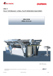
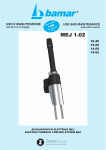
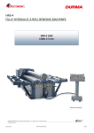
Pando P-755 / P-756 (60-90-120) V850 S.E.C. System User Manual, installation and guarantee certificate Business Quality Management Certificate UNE-EN ISO 9001:2000 The International Certification Network Quality Management System ISO 9001:2000 UNE EN 60335-1 UNE EN 60335-2-31 CEE DISPOSAL OF ELECTRICAL APPLIANCES ES ** This symbol on the product or its packaging indicates that this product cannot be disposed of as normal domestic waste. This product must be taken to a collection point for electrical and electronic equipment for recycling. By ensuring that this product is disposed of correctly, you help to avoid negative consequences to the environment and public health, which could be the case if the product is not correctly disposed of. For more information on recycling of this product, contact the local authorities in your city, their domestic waste collection service or the shop where you purchased the product. This electrical appliance is marked in accordance with European Directive 2002/96/EC on waste and electrical equipment (WEEE). INTRODUCTION We would like to congratulate you for choosing a Pando Extractor Hood and thank you for your confidence in our company. This manual is an installation, use and maintenance guide for your new Extractor Hood CONTENTS 1. Safety instructions ..........................................................................................................Page. 3 2. Installation manual. Instructions for panelling attachments……………………………. …Page 4 - 12 Installation instructions and advice..................................................................................Page 13 - 17 3. Technical specifications of models. .................................................................................Page. 18 4. Instructions on use of controls. ........................................................................................Page. 19 5. Cleaning and maintenance. ..............................................................................................Page. 20 - 23 6. Troubleshooting. ...............................................................................................................Page. 24 - 25 7. Post-sales technical service, Guarantee Certificate and Serial Number...........................Page 26 This manual is valid for different models, to determine which parts and functions correspond to your hood model, CONSULT THE ATTACHED ASSEMBLY MANUAL The manufacturer will not be held liable for any inexactitude attributable to printing or transcription errors in this manual. The manufacturer reserves the right to modify these products as necessary or convenient, without affecting their essential functional and safety characteristics. 02 of 20 1. SAFETY INSTRUCTIONS This appliance is designed for use by adults, it must not be used by children or people with reduced physical, sensorial or mental capacity or who lack experience or knowledge, unless they are under the supervision of or have been instructed by people responsible for their safety. Children should be kept under control so they do not play with the appliance. On receiving the appliance, it should first be unpackaged immediately. Check its general appearance and if any anomalies are detected, the retailer or installer should be informed immediately. This appliance has been designed for domestic use. It should not be subject to industrial or professional use, or for any purposes other that those is has been designed for. The manufacturer’s guarantee will not apply to any consequences or harm resulting from inadequate installation or usage of this appliance. Do not modify any of the characteristics of this appliance, as this can be dangerous. Repairs should only be carried out by an authorised and specialised technical service. To avoid hazards, it is forbidden to modify the appliance, this includes replacement of the electric power cable. Take special care when perforating walls or ceilings to avoid electric cables, pipes, metal girders, etc. These elements could cause serious damage, electric shocks or transmission or noise and vibration. IMPORTANT: Before connecting the device to the mains, always disconnect the power supply (Circuit breaker on the house electric panel). WARNING: Before any cleaning or maintenance operations, always disconnect the hood from the mains, either by unplugging it or using the house circuit breaker on the general electric panel. Never use steam or high-pressure equipment to clean the hood (Electrical safety precautions). Do not cook food directly on the flame or have the burners operating without cooking recipients on them (The flames could be sucked up and damage the appliance, this would not be covered by the guarantee. This appliance must not be used over solid fuel cookers (Wood, coal…). Frying operations must be constantly monitored to avoid oil and grease reaching very high temperatures and inflaming. Do not do flambé cooking under the hood. Take care, as there is a risk of getting burnt when touching accessible parts that could be hot after cooking. Follow the recommendations on frequency for cleaning and replacement of filters. Accumulation of deposited grease can be a fire hazard. Never use the hood without its anti-grease filter. The installation must abide by current regulations concerning ventilation in closed premises. Specifically, the air evacuated should not be led to a conduit used for exhausting the fumes from other appliances using gas or other fuels (Central heating installations, etc.). Ensure there is adequate ventilation in the premises when using the hood When the “suction system” hood is used at the same time as a source of heat (Gas, oil or coal heater, fireplace, etc.), make sure that the hood is not sucking part of the air destined for combustion, as this would create a depression. It is always advisable to consult with the manufacturer of the heater, fireplace, etc. in order to obtain optimum operation without hazards. There should be a maximum depression of 0.04 mbar. These conditions will ensure optimum operation of the hood. To achieve these conditions, it is necessary to have a permanent air inlet so as to avoid air stagnating (It is recommendable to have a ventilation grille for this purpose). Doors and windows are not enough. The mains electrical supply must be stable and of the required characteristics: 220/240v AC, 50Hz. If the power supply is not stable and has voltage or frequency oscillations, spikes, overloads, there are electric storms, etc. The hood could malfunction and even be damaged, such damage will not be covered by the guarantee. If this were to occur, disconnect the hood and contact an electrician or the electric company in order to solve the supply problem. The hood is an electrical appliance for extracting fumes and must not be used as an element for supporting objects or utensils. We reserve the right to modify technical, functional or design characteristics of this appliance with the aim of constantly improving the product. 03 of 20 2. INSTALLATION MANUAL Height of the hood over the cooker worktop. Measurements of the four holes that must be made in the wall to hang and secure the hood. 04 of 20 05 of 20 06 of 20 ES Instructions for fitting and adjusting the hardware: KB-70-D for hoods 60 and 90 cm wide. KB-75-D for hoods 120 cm wide. 07 of 20 ES Instructions for fitting and adjusting the hardware KB-70-D and KB-75-D Dear client, In order to guarantee a fault-free service life, it is necessary to follow these assembly recommendations. We are at your disposal for any query. Usage KB-70-D: For a hood 60 or 90 cm wide. Weight of the folding doors Made of red pine (0.45 kg/dm3), 16 mm thick, without handle up to MDF material (0.85 kg/dm3) 22 mm thick with a bar handle. Blue spring (Force spring) Height of the cabinet Weight of the door with handle* in kg in mm Min. Max. Width of the door in mm Weight 0.45 kg/dm3 (e.g. pine) With a With a standard bar handle handle Weight 0.65 kg/dm3 (e.g. chipboard) With a With a bar standard handle* handle Weight 0.85 kg/dm3 (e.g. MDF) With a With a bar standard handle* handle 300 2.5 – 8.5 1000 – 1200 600 – 1200 700 – 1200 550 – 1200 500 – 1200 450 – 1100 350 400 450 500 550 600 2.3 – 7.5 2.1 – 6.8 2.0 – 5.8 1.8 – 5.0 1.6 – 4.6 1.4 – 4.2 750 – 1200 600 – 1200 500 – 1200 400 – 1150 300 – 1000 300 – 800 500 – 1200 400 – 1200 300 – 1000 300 – 800 300 – 650 300 – 600 500 – 1200 400 – 1200 400 – 1000 300 – 800 300 – 650 300 – 550 450 – 1200 350 – 950 300 – 800 300 – 650 300 – 550 300 – 400 400 – 1200 300 – 1000 300 – 800 300 – 600 300 – 500 300 – 400 350 – 900 300 – 750 300 – 600 300 – 500 300 – 400 300 – 350 * Bar handle is calculated at a weight of 0.15 kg / 100 mm of width of handle In limit applications (Minimum or maximum), we recommend a test assembly first. Changing the springs (Power spring) Take the springs to the minimum position, turning the adjustment screws to the left. Change the springs with the mechanism completely open. 08 of 20 ES Instructions for fitting and adjusting the hardware KB-70-D and KB-75-D Usage KB-75-D: For hoods 120cm wide. Weight of the folding doors Made of red pine (0.45 kg/dm3), 16 mm thick, without handle up to MDF material (0.85 kg/dm3) 22 mm thick with a bar handle. Height of the cabinet Weight of the door with handle* in kg in mm Min. Max. Width of the door in mm Weight 0.45 kg/dm3 (e.g. pine) With a With a standard bar handle handle Weight 0.65 kg/dm3 (e.g. chipboard) With a With a bar standard handle* handle 400 7.0 – 11.0 1200** 1200** 1200** 450 6.7 – 9.6 1200** 1200** 1200** 500 550 600 5.8 – 8.5 5.6 – 7.6 5.2 – 7.0 1200** 1200** 1000 – 1200** 900 – 1200** 850 – 1100 700 – 950 950 – 1200** 850 – 1100 700 – 950 1100 – 1200** 950 – 1200** 750 – 1050 650 – 850 550 – 700 * Bar handle is calculated at a weight of 0.15 kg / 100 mm of width of handle ** It is possible to have a wider door (Request reports) Weight 0.85 kg/dm3 (e.g. MDF) With a With a bar standard handle* handle 1100 – 1200** 950 – 1200** 700 – 1050 650 – 850 550 – 700 950 – 1200** 800 – 1100 600 – 900 550 – 700 475 – 600 In limit applications (Minimum or maximum), we recommend a test assembly first. KB-70-D hardware Left-hand side: D2.70.0303.1 Right-hand side: D2.70.0302.1 KB-75-D hardware Left-hand side: D2.75.0003.1 Right-hand side: D2.75.0004.1 Opening angle 110° 09 of 20 ES Drilling side walls and wooden doors KB-70-D/KB-75-D Left hand side of the cabinet (Right hand side of the cabinet reflected) Securing to the side: 4 x Countersunk Euro screws *Distance thickness of tampon 2 mm Top of furniture Door Side The measurements indicated must be followed exacty! Holes for wooden door Door indicated Minimum gasket: 0 Upper covering 38 – thickness of the ceiling + Upper covering Attention! Always install the mechanism in open position! Securing with woodscrews Ø 4 mm / 2 x Side covering 24 + Side covering 10 of 20 ES KB-70-D / KB-75-D holes for door with an aluminium frame Holes for narrow securing angle Minimum gasket: 0 Upper covering 58 – thickness of the ceiling + Upper covering Attention! Always install the mechanism in open position! Securing with woodscrews Ø 4 mm / 2 x Side covering 19 + Side covering Holes for doors with a 19 mm aluminium frame (Side covering 12-17 mm) 54 – thickness of the ceiling + covering Standard section 19 mm glass slats Side covering Flat head screw DIN 7985-M4x8-Z height of stamping Upper covering Minimum gasket: 0 Top of furniture side 11 of 20 ES Instructions for adjustment KB-70-D and KB-75-D Adjusting the height of the door Height adjustment of the door is done for wooden doors by direct eccentric adjustment, in the case of an aluminium frame, using the oblong holes on the securing angle: Direct eccentric adjustment (See illustration on the right): 1. Remove securing screw 1 2. Adjust the height of the tramite screw 2 (± 2 mm) 3. Tighten securing screw 1 Adjusting tramite oblong holes (Not illustrated) 1. Loosen the screws 2. Adjust the height (± 2 mm) 3. Tighten the screws Adjusting KB-70-D and KB-75-D to the weight of the door With the KB-70-D and KB-75-D hardware, it is possible to open the raising doors to a max. angle of: 110°. By correctly adjusting the power of the spring, the door will remain open in any position over 45°. Thus you can choose the best opening angle for your needs. Adjusting the power of the spring: Turning the adjusting screw to the right = increasing the power of the spring Turning the adjusting screw to the left = decreasing the power of the spring (The screws should be adjusted to the same tension in both hardware parts.) adjustment screw Adjusting the damper Adjust the closing speed with the damper adjustment screw. Turning to the right reduces the closing speed Turning to the left increases the closing speed. damper adjustment screw Precaution! No not dismantle the damper, so as not to damage it. Refit the cover after adjusting the doors and the damper. 12 of 20 2. INSTALLATION INSTRUCTIONS AND TIPS (The entire installation process must only be carried out by qualified technicians, professional fitters or the official technical service). Before proceeding with the installation, make sure that all the components are in perfect state. If this is not the case, contact the supplier and do not proceed with the installation. Any damage on the appliance, such as scratches, dents, etc. reported after installation will not be covered by the guarantee. 2.1. INSTALLING THE SUCTION MOTOR If it is not possible to exhaust the cooking fumes and vapours to the outside, it is possible to use a filter version hood (Fig. 1) (Depending on versions, consult with the distributor) fitting an active carbon filter kit. The fumes and vapour will be expelled and recycled from the upper grille A. Please be aware that suction will be less in this version and the sound level will be greater. The hood is fitted with an upper air exhaust for discharging the fumes to the outside (Suction version - Fig. 2). If possible, this is the best option. (Fig. 1) Filter version hood (Fig. 2) Suction version hood 1 of 20 Please take special note of all the instructions given below. The air evacuation tube should be as short as possible. Limit the number of curves and if used, ensure they are as open as possible Use material approved by current regulations. Avoid drastic section changes (Constant diameter, consult examples). VERY IMPORTANT: INOXPAN S.L. WILL NOT BE RESPONSIBLE FOR THE OPERATION OF ITS APPLIANCES IF THEY ARE NOT CONNECTED TO A FUME EXHAUST CONDUIT OF THE RECOMMENDED DIAMETER FOR EACH MOTOR VERSION. TYPE OF CONDUIT: Performance will depend on the material used for the conduit. The type of material can affect the sound produced and friction offered to the airflow. For a soundproofed installation, we recommend using our special SEC System fume extractor conduit material. Consult our distributor. HEIGHT CALCULATION: The ideal height from the worktop the lower part of the body of the hood is 65 cm (Depending on the model). It the height is greater, there is a risk of the fumes escaping (Fig. page 5). WIDTH OF THE HOOD: The hood must always be wider than the cooking area. If it is narrower, there may be a risk of fumes escaping from the ends (Fig. Page 5). (Depending on models) CENTRING THE HOOD: The hood must be centred in such a manner that its filters are centred over the cooking area. VENTILATION AND DRAUGHTS: The hood installation must have an air inlet, preferably opposite the hood and without a second inlet that could cause draughts. Without an air inlet there will depression problems and atmospheric over-pressure and the hood motor will not work at full performance. EXTERNAL EXIT OF THE CONDUIT: The outlet to the exterior should have a hatch opening with overpressure (Fig. page 5). Under no circumstances should a gas grille or similar that obstructs the passage of air be used. Neither should the air exit be uncovered, as this could allow external elements to enter (water, strong wind, birds nests, etc.) obstructing the airflow out, and this could damage the hood. REDUCING THE DIAMETER OF THE FUME CONDUIT TUBE: The following indications should be taken into account when, due to the routing of the conduit, it is necessary to reduce its diameter. The first thing that must be clear is that to reduce the diameter of the tube ALWAYS IMPLIES A LOSS OF SUCTION. Therefore, if this is necessary, you MUST take into account the premises indicated on page 6. ANTI-RETURN VALVE: These are advisable in community installations where several conduits are joined to a common conduit, to avoid backdraughts of fumes and the consequent entry of fumes and smells from other hoods, etc. 13 of 20 Optimum height 650 mm (Depending on models) Optimum height 650 mm Wall Hood Island Hood Note: The minimum distance should be 650 mm. Also take into account the distance indicated by the manufacturer of the cooker in case this is greater. The optimum distance between the worktop and the base of the hood is 650 mm. A greater height implies the risk of fumes escaping round the sides of the hood. GOOD BAD NOTE: Centre the hood over the cooking area Trap doors opening by overpressure (not included) (Not included) Anti-return valves (not included) (Not included) The manufacture will not be held responsible for problems of airflow or noise levels if all these instructions are not followed. 14 of 20 Drawing A Fume exit tube Conduit reduction Hood connection 1. Never reduce the diameter of the tube just after the hood connection. (Only in versions with motor from V850, with smaller motors V700/800 it is possible to fit a reduction of Ø150 - Ø120) Drawing B Reduction of Ø 150mm - Ø 135 mm Reduction of Ø 135mm - Ø 120 mm Tube Ø 150 mm Tube Ø 135mm Tube Ø 120 mm 2. Always reduce the tube diameter gradually. Drawing C BAD Conduit reduction GOOD 3. Never reduce the diameter where there are curves or elbows, always do it in the straight sections and as far from the hood as possible. Drawing D WORSE BETTER 4. Avoid an excessive number of curves or elbows if possible. If there is no other option, try to make them with the largest angles possible. * IMPORTANT: Whenever there are two changes in the conduit, such as angles or diameter reductions, there must be at least 1 m distance between them, to allow for the recovery of speed and pressure of the airflow. For example, if two 90º elbows are fitted and the distance between them is 20cm, this would cause a blockage effect, drastically reducing suction power and increasing noise levels. * IMPORTANT: Always avoid downward facing conduit sections, as this drastically reduces the extraction capacity. 15 of 20 2.2. CONNECTING THE CONDUIT TO SEC TUBE: (Included only in SEC System versions, V850/950/1150/1350) Premises pre-installation CLAMP OR ALUMINIUM ADHESIVE TAPE (Not included) SEC TUBE System (included) Only in versions V850/950/1150/1350 CLAMP OR ALUMINIUM ADHESIVE TAPE (Not included) Motor ATTENTION: Never use the Sec tube as a cover for a tube of smaller diameter than the preinstallation of the premises. This tube is not intended to cover any other tube. 16 of 20 2.3. ELECTRICAL CONNECTION: (Exclusively for qualified technicians) It is recommended to have an independent line from the electric panel to supply power to the hood so as to avoid interference in the hood from fluorescent tubes or other devices that create electrical noise. ATTENTION! Disconnect the appliance from the mains before carrying out any operation on the inside of the hood. Make sure you do not disconnect or cut any electric cables inside the hood, if this were to occur, contact the nearest technical assistance centre. Electrical connection should be carried out by qualified personnel. Connection should be in compliance mandatory regulations. Before connecting the Hood, make sure that the mains voltage and the hood specifications coincide (See identification plate inside the appliance). If the Specifications label inside the hood displays the symbol ☐ the appliance is class II. In this case, it does not need an earth connection. If the Specifications label inside the hood does NOT display the symbol ☐, the appliance is class I and in this case it needs an earth connection. VERY IMPORTANT DO NOT REMOVE THE PROTECTIVE PLASTIC ON THE HOOD UNTIL IT HAS BEEN COMPLETELY INSTALLED The mains plug must be accessible. If the mains cable is broken, your official Pando Technical Service should be contacted for its replacement. If the mains plug cannot be accessible, to avoid hazards, a fixed omnipolar switch should be fitted so that the appliance can be disconnected from the mains, the distance between open contacts should be at least 3 mm. The cable connecting the hood and the motor, in "Roof Motor" models, will be of H07RN-F class, section 3 x 1 mm. (Up to the length of 5 m) and section 3 x 2.5 mm (Up to the length of 25 m). The extractor hood must "always “be connected to an installation with good "earthing". Pando will not be held liable for any harm caused by the non-observance of this requirement (except appliances of Class II, indicated with this symbol ☐ ). Power cable colour coding: Green / Yellow = Earth Blue = Neutral Brown = Live The manufacturer will not be held liable for any accident caused by the lack of earthing or a faulty earth connection. If the power cable is damaged, call post-sales technical assistance for it to be replaced and avoid hazards. The appliance must be disconnected from the mains during the installation process and maintenance operations. 17 of 20 3. TECHNICAL SPECIFICATIONS OF MOTORIZATIONS INTERIOR or BUILT-IN motor Conduit diameter in mm suction UNE-EN-61591 min. /max. V.500 INT - Ø120 V.600 INT - Ø120 V.700 INT - Ø120 V.800 INT - Ø120-Ø150 V.1050 INT - Ø150 150/305 m³/h 150/380 m³/h 220/547 m³/h 220/634 m³/h 220/896 m³/h Sound level UNE-EN 60704-213 Min. / Max. Lp (dBA) 45/55 43/52 43/58 43/65 43/68 Motor consumption in Watts 100W 185W 180W 200W 340W Recommended conduit installation Up to 4 m linear Up to 4 m linear Up to 4 m linear Up to 4 m linear Up to 4 m linear INTERIOR or BUILT-IN motor SEC System Conduit diameter in mm V.850 SEC System V.950 SEC System V.1150 SEC System V.1350 SEC System INT - Ø150 INT - Ø150 INT - Ø150 INT Ø150-200 suction UNE-EN-61591 min. /max. Sound level UNE-EN 60704-2-13 Min. / Max Lp (dBA) Motor consumption in Watts Recommended conduit installation 262/680 m³/h 262/750 m³/h 280/940m³/h 320/1100 m³/h 38/55 32/51 39/55 39/64 197W V.1700 EXTERIOR motor on WALL Conduit diameter in mm suction UNE-EN-61591 min. /max. Sound level UNE-EN 60704-2-13 Min. / Max Lp (dBA) Motor consumption in Watts Recommended conduit installation 150W Up to 6m linear Up to 6m linear V.2300 on WALL WALL - Ø200 380/1500 m³/h 48/75 Conduit diameter in mm suction UNE-EN-61591 min. /max. Sound level UNE-EN 60704-2-13 Min. / Max Lp (dBA) Motor consumption in Watts Recommended conduit installation V.1900 On ROOF ROOF Ø200 ROOF Ø200 380/2100 m³/h 380/1090 m³/h 380/1502 m³/h 46/70 45/53 48/56 310W EXTERIOR motor 355W Up to 6m linear V.1300 on ROOF WALL - Ø150 Up to 6 m linear 200W Up to 6m linear 330W Up to 6 m linear 198W Up to 9,5 m linear 306W Up to 15 m linear V.1200 V.1400 V.2100 EXT - Ø150 EXT Ø150-200 EXT - Ø200 280/1000 m³/h 320/1173 m³/h 380/1716 m³/h 45/62 41/57 55/69 265W Up to 6 m linear, max. distance between hood and motor 2 m. 355W Up to 11m linear, max. distance between hood and motor 4m. 225W Up to 11m linear, max. distance between hood and motor 4m. *Limit the number of curves in the conduit, as each curve will reduce suction efficacy. In Ø150 mm a 90º elbow = 1 m linear. In Ø200 mm, a 90º elbow = 2.5 m lineal. E.g. If two 90º elbows are used, the total length of a conduit of 3 m linear Ø150 mm, is 5m. E.g. If two 90º elbows are used, the total length of a conduit of 3 m linear Ø2000 mm, is 8m. NOTE: Versions V850/950/1150/1350 with interior motors, have a SEC tube System of 0.5 m as standard, to connect the motor outlet with the pre-installation of the premises. NOTE: Versions V600/700 and 800 with internal motors have a reduction ring of Ø 150 mm - Ø 120 mm. 18 of 20 4. INSTRUCTIONS FOR USING THE CONTROLS. A - Remote control receiver cell (*optional, included or not depending on model and version). B – Pressing this button starts the motor in 1st speed, minimum suction. Pressing it again stops the motor. C – Press this button to reduce motor speed. D – Display screen indicating the speed in numbers. E – Press this button to increase motor speed. F - Timer or Last time: Press this button (It will flash) and the hood will remain at the desired speed for 5 minutes, after this time the hood will automatically stop (Motor and lights). It is advisable to use this function when you have finished cooking, to evacuate the remaining fumes and vapours in the premises, which could condense in the hood and the extractor conduit. G – Press this button to switch the lights on or off. 5.4. MAINTENANCE AND CHANGING OF LAMPS. DICHROIC LAMP a) Make sure the appliance is disconnected from the mains. b) Remove the lamp using a screwdriver (See figure). c) Replace the lamp with a similar one (Dichroic max. 20 W, 12 Volt). BI-PIN SQUARE LAMP a) Make sure the appliance is disconnected from the mains. b) Open the window completely up to 90º (See figure), pressing on PUSH. c) Replace the lamp with a similar model (BI-PIN max. 20 W, 12 Volt, G4 connection). d) Close the window. If the window does not close correctly, repeat point B). 19 of 20 5. MAINTENANCE AND CLEANING Careful maintenance will guarantee the good operation and performance of the appliance for a long time. WARNING: Whenever you access the inside of the extractor hood for maintenance (Qualified personnel) or cleaning, make sure it is disconnected from the mains. For this purpose, the plug should be easily accessible. Non-observance of the instructions regarding hood cleaning and filter change could be a fire hazard. 5.1 CLEANING THE HOOD ENAMELLED HOODS The hoods are epoxy enamelled and baked at 200°. This coating is exceptionally hard and durable. Nevertheless, its qualities can be significantly impaired depending on the products used for cleaning and maintenance. The best solution for cleaning the EXTERIOR of the hood is with soapy water, using a neutral antigrease detergent and rinsing and wiping with a damp cloth. DO NOT USE SCOURING PADS that can scratch the enamel, only use a soft cloth or sponge. Avoid soaking the hood when rinsing, so water cannot be retained in the joints and cause rust in time. If you decide to use other cleaning products, we recommend that they do not scratch the enamel and DO NOT CONTAIN Silicon, AMMONIA, CAUSTIC SODA or DERIVED PRODUCTS. STAINLESS STEEL HOODS To clean and maintain stainless steel, apply the same procedure as for enamelled hoods, with a neutral soapy water solution applied with a cloth and rinsed with another damp cloth. When the hood is dry, you can apply the "Pando lnox stainless steel cleaner" to obtain a final homogenous and perfect finish. IT IS HARMFUL TO USE ACIDS, CAUSTIC SODA, AMMONIA, CHLORIDES or DERIVED PRODUCTS to clean stainless steel. These products will destroy the chemical characteristics of the metal and can cause total or partial oxidation, blackening, stains, etc. Take special care with acids (Hydrochloric, bleach, etc.). In some cases it is not necessary to apply the product directly onto the stainless steel to damage it, as even the vapours they give off could affect the metal. In models with the Sec System tray, it is forbidden to dismantle them or remove them from the hood for cleaning. The visible external part of this tray will be cleaned. 20 of 20 OIL TRAY: There is a container inside the hood, under the filter, which collects any fluid that condenses and runs down from the hood filter. This container requires regular maintenance and needs to be emptied when full and cleaned. ATTENTION! Before carrying out any maintenance or cleaning work on the hood or any of its components, make sure that it is disconnected from the mains. Instructions for removing and replacing the oil tray are detailed below: 1. - Remove the filter, unscrew the SEC System tray. 2. - Remove the container, pulling upwards and then backwards, it is secured by means of 2 powerful magnets. 3. - When the container is cleaned, replace it in its original location, ensuring that is it well secured by the 2 magnets. See figure No. 4. 4 – Enlarged drawing of the container correctly secured by the magnets, the front edge of the container must be correctly adjusted under the front edge of the hood, see illustration. Once fitted, screw in the SEC tray and fit the filter. 21 of 20 VERY IMPORTANT: During industrial cleaning after new construction work or reforms, the kitchen area must be perfectly ventilated after cleaning to avoid an accumulation of the aforementioned “smoke or vapour” Not doing this could cause irreparable damage to the stainless steel. People in charge of cleaning must also take into account that they should not use the cleaning products described above, which could seriously damage the stainless steel. RECOMMENDATIONS: When cleaning the hood with soft cloths, always rub in the direction of the polishing of the hood (horizontal o vertical), to avoid producing scratch marks. Then, to even out the texture and sheen of the surface, apply the exclusive product "Panda Stainless Steel Cleaner, Polish and Protector", a product that you can purchase in your regular distributor or through our wide range of Technical Assistance Services. ALUMINIUM AND STAINLESS STEEL FILTERS: The metal filters fitted to the hoods are made of aluminium section and mesh made of the same metal. It is important to bear in mind that these filters should be replaced when they are deteriorated, as they are an effective firebreak in case of sporadic flames (It is evident that these filters must ALWAYS be perfectly clean and free of grease). They can be hand washed in standard anti-grease soapy solution or in a dishwasher. when hand washing, it is recommended NOT TO USE SCOURING PADS, as they could damage the alloy mesh, the best thing is to wash by immersion and then rinse. VERY IMPORTANT: If a DISHWASHER is used, follow the manufacturer’s instructions regarding washing "ALUMINIUM UTENSILS". Nevertheless, ALWAYS wash with a SHORT PROGRAM, NOT USING DRYING OR POLISHING. If a complete program with drying and polishing is used by mistake, the filters may be blackened or stained in different tones. RECOMMENDATIONS: It is recommended to wash the filters at least every 10 days. Under conditions of average normal use, it is recommended to replace the aluminium or stainless steel filters once a year. To remove the metal anti-grease filter, just pull the handle until it projects from the front guide, tip the filter slightly downwards and extract it from the rear guide. To insert the new filter, repeat the same operation in reverse. 22 of 20 5.3. MAINTENANCE OF THE ACTIVATED CARBON FILTER (Only the filter version): (Fig. 1 Page 4) Recirculation or recycling of the air extracted by the hood is carried out through special activated carbon filters. It is designed to purify the extracted fumes and send the air back to the kitchen. This type of appliance should only be used when it is not possible to install a conduit to extract the fumes outside the kitchen, or when the smoke or smell of the fumes could disturb others at the outlet. This type is also proposed for ecological purposes, to avoid emitting pollutant gases into the atmosphere. The incorporation of activated carbon filters implies a loss of hood suction capacity, as the air must go through metal filters + the activated carbon filters. It is recommended to change the filters every 6 months (Depending on usage) although they can remain effective for 1 year if the user keeps the metal filters clean so as to avoid the carbon filters getting soaked in grease, which would obstruct the surface fibres. The activated carbon filters cannot be washed or regenerated. System A Hood and Filter Assemblies up to 600 Fan blades horizontal Activated carbon filter: Placed above the motors and secured with a quarter turn System B 700 / 800 Hood and Filter Assemblies Fan blades vertical Activated carbon filters: Placed above the motors and secured with a quarter turn System C Hoods with carbon filters in SEC tray Aluminium filter Activated carbon filters: System D 800 / 850 / 950 / 1050 / 1150 Hood and Filter Assemblies BGF system motors in vertical position Support plate for carbon filters Activated carbon filters: Placed above the support plate and secured with a clip 23 of 20 6. TROUBLESHOOTING PROBLEM The hood is not working… SOLUTION Make sure the hood is connected to the mains; check the plug and the electric panel circuit breaker. Reset: Disconnect the electric panel circuit breaker that supplies the hood (Lower the switch). Wait for 2 minutes and then connect the circuit breaker. Call the official technical service. Reset: Disconnect the electric panel circuit breaker that supplies the hood (Lower the switch). Wait for 2 minutes and then connect the circuit breaker. Check the state of the filters, clean and replace if necessary. Check the extractor conduit for obstructions. Contact the distributor to verify that the installation is correct. Call the official technical service. Make sure that it is not in timer mode (last time). Make sure the hood is connected to the mains; check the plug and the electric panel circuit breaker. Ensure that there are no electrical supply problems such as voltage fluctuations. Call the official technical service. Reset: Disconnect the electric panel circuit breaker that supplies the hood (Lower the switch). Wait for 2 minutes and then connect the circuit breaker. If it is safely accessible, check that the external outlet is not obstructed. Contact the distributor to verify that the installation is correct. Call the official technical service. See bulletin INM0004, Page 21 Reset: Disconnect the electric panel circuit breaker that supplies the hood (Lower the switch). Wait for 2 minutes and then connect the circuit breaker. Change the bulb. Call the official technical service. Reset: Disconnect the electric panel circuit breaker that supplies the hood (Lower the switch). Wait for 2 minutes and then connect the circuit breaker. Call the official technical service. Hood performing poorly…it does not suck… The hood stops working… The hood is very noisy… The hood forms condensation... The lights do not come on .... Button panel not working ...... RESET NOTE: Our hoods are designed with circuits that have a blocking protection system that in some cases avoids damage caused by small variations in the electrical supply, To override this lock, use the resetting procedure indicated in the table above. 24 de 20 BULLETIN IN_M0004: HOOD CONDENSATION Referring to a condensation problem (Dripping from the lower part of the hood) with stainless steel hoods installed over induction, vitro-ceramic…hotplates. This problem may have several separate or joint causes. One is the use of the hotplate at maximum power without preheating, inadequate use or maintenance of the hood, and/or incorrect installation of the extractor conduit. This condensation can be explained as follows: The steel is cold, if we start cooking at maximum power, the hot steam comes into contact with the steel too quickly (The steel has had no time to warm up) causing the condensation effect and the consequent dripping. (This effect is worsened in the case of induction hotplates that heat up very quickly). If, additionally, the evacuation conduit is inadequate, the problem is compounded, because it is narrower than recommended by the manufacturer, for example, water vapour is not totally evacuated and the amount left stays in the hood. When the hood cools, it condenses and drips. It additionally creates the vapour reversal effect that affects the suction capacity. MOTOR VERSION V.600 INTERIOR V.700 INTERIOR V.800 INTERIOR V.850 INTERIOR V.950 INTERIOR DIAMETER OF CONDUIT # 120mm # 120mm # 120mm o # 150mm* # 150mm # 150mm MOTOR VERSION V.1150 INTERIOR V.1350 INTERIOR V.1400 EXTERIOR V.2100 EXTERIOR V.1300/V.1900 ROOF DIAMETER OF CONDUIT # 150mm # 150mm # 150mm or # 200mm* # 200mm # 200mm INOXPAN S.L. will not be held liable for the malfunctioning of its appliances if they are not connected to an installation with the right diameter tube, as indicated in the table above. Induction, Vitro-ceramic… hotplates, if not used correctly can generate condensation problems, due to the difference of temperature, which after some time in operation, could derive in the droplets joining and showing their presence in the metal filters or in the lower part of the hood. Advice for avoiding hood condensation: (In addition to correct installation) Switch on the hood 5 minutes before starting cooking and when finished, set the timer (LAST TIME) to evacuate the fumes in the conduit. This will ensure total evacuation. Do not start cooking at maximum power, i.e., start at low or medium power, to allow time for the steel at the bottom of the hood to warm up. Keep the filters clean, proceeding with their cleaning at least every 10 days, and if deterioration is detected, replace them. Have a continuous air inlet in the room so as not to generate a depression that would affect the suction power. (Ventilation grille, semi-open window…). Follow the advice given in the instructions for induction hotplates as regards condensation. 25 of 20 7. TECHNICAL POST-SALES SERVICE, GUARANTEE CERTIFICATE AND SERIAL NUMBER OF THE HOOD TECHNICAL POST-SALES SERVICE (SAT): INOXPAN S.L. TEL. 90241 55 10 I FAX: 93 757 9653 E-MAIL: [email protected] To request technical assistance, either within or outside the guarantee, call the telephone number indicated above, or send a fax or e-mail. Interventions will be covered by the guarantee only if the defect can be attributed to the product, problems caused by inadequate installation of the hood or the extraction conduit, external anomalies in the electrical supply, installation or operation revisions, cleaning, changing of consumables such as filters light bulbs, lamp windows … will not be covered by the guarantee and the transport and labour expenses will be paid to the Technical Attention Service. GUARANTEE CERTIFICATE: INOXPAN, S.L., as the manufacturer of this appliance, guarantees for a period of two years from the purchase date, all manufacturing defects that affect it correct operation as well as any possible damage caused by this. During this period, the Company will repair or replace free of charge any fault part attributable to manufacturing faults or defects of the appliance until correct operation is achieved, this includes the labour necessary for these repairs or replacements, including transport of company personnel. This guarantee does not cover defects caused by misuse, incorrect installation, faulty energy supply (See instruction manual), defects cause by transport or intervention of personnel apart from this company, not authorised by the same or caused by force majeure, such as bulbs, glass, plastic and enamel that has been damaged due to the aforementioned causes, as well as the case of inadequate extraction conduits (See instruction manual). INOXPAN, S.L., will expressly not be held liable for direct or indirect damage or harm to people personas due to breakdown of malfunction of the appliance caused by inadequate manipulation of the same. This guarantee will only be valid if correctly filled in with the model, serial number, stamp of the distributor as well as the purchase invoice indicating date of purchase. This guarantee will not be valid if the appliance is used for other purposes than for the domestic use it was designed for. Everything not expressly established in this certificate will be covered by the General Law for the Defence of Consumers and Users, Law 26/84, of 19 July as well as the Law on retail Commerce, Law 7/96, of 13 January. MODEL SERIAL NO. DISTRIBUTOR´S STAMP 26 of 20 NOTES: EXCLUSIVE PRODUCT STAINLESS STEEL CLEANER, POLISH AND PROTECTOR PROPERTIES: Degreaser especially recommended for polishing stainless steel surfaces, with a complex formula based on paraffin derivatives that leaves an invisible film that protect and polished the surface protector. APPLICATIONS: Cleans, polishes and evens out stainless steel surfaces on extractor hoods and stainless steel kitchen furnishings. 27 of 20 3011000002400 Business Quality Management Certificate UNE-EN ISO 9001:2000 The International Certification Network Quality Management System ISO 9001:2000 Pando Manufactured by INOXPAN, S.L. Pol. Ind. El Cros - Camí del Cros, s/n Apdo. Correos nº 21 08310 ARGENTONA (Barcelona - Spain) Tel. +34 93 757 94 11 Fax +34 93 757 96 53 www.pando.es [email protected]