1
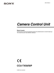
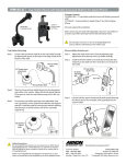
INSTALLATION & OPERATION
INSTRUCTIONS
ICW-3 WINDOW INTERCOM
9350-7686-000 Rev. G 11/2002
TRADEMARKS
AudioCom® is a registered trademark of Telex Communications. Names of other products mentioned herein are used for identification purposes only and may be trademarks and/or registered trademarks of their respective companies.
WARRANTY INFORMATION
Products are warranted by Telex Communications, Inc. to be free from defects in materials and workmanship for a period of one
year from the date of sale.
The sole obligation of Telex during the warranty period is to provide, without charge, parts and labor necessary to remedy covered
defects appearing in products returned prepaid to Telex. This warranty does not cover any defect, malfunction or failure caused
beyond the control of Telex, including unreasonable or negligent operation, abuse, accident, failure to follow instructions in the
manual, defective or improper associated equipment, attempts at modification and repair not authorized by Telex, and shipping
damage. Products with their serial numbers removed or effaced are not covered by this warranty.
To obtain warranty service, follow the procedures entitled “Procedure for Returns” and “ Shipping to Manufacturer for Repair or
Adjustment”.
This warranty is the sole and exclusive express warranty given with respect to Audiocom products. It is the responsibility of the
user to determine before purchase that this product is suitable for the user’s intended purpose.
ANY AND ALL IMPLIED WARRANTIES, INCLUDING THE IMPLIED WARRANTY OF MERCHANTABILITY ARE LIMITED TO THE
DURATION OF THIS EXPRESS LIMITED WARRANTY.
NEITHER TELEX NOR THE DEALER WHO SELLS TELEX PRODUCTS IS LIABLE FOR INCIDENTAL OR CONSEQUENTIAL
DAMAGES OF ANY KIND.
CUSTOMER SUPPORT
Technical questions should be directed to:
Customer Service Department
Telex
12000 Portland Avenue South
Burnsville, MN 55337 U.S.A
Telephone: (952) 884-4051
Fax: (952) 884-0043
RETURN SHIPPING INSTRUCTIONS
Procedure for Returns
If a return is necessary, contact the dealer where this unit was purchased.
If a return through the dealer is not possible, obtain a RETURN AUTHORIZATION from:
Customer Service Department
Telex Communications, Inc.
Telephone: 1-800-392-3497 or (952) 884-4051
Fax: 1-800-323-0498 or (952) 884-0043
DO NOT RETURN ANY EQUIPMENT DIRECTLY TO THE FACTORY WITHOUT FIRST OBTAINING A RETURN AUTHORIZATION.
Be prepared to provide the company name, address, phone number, a person to contact regarding the return, purchase order
number, the type and quantity of equipment, a description of the problem and the serial number(s).
Shipping to Manufacturer for Repair or Adjustment
All shipments of products should be made via United Parcel Service or the best available shipper prepaid. The equipment should
be shipped in the original packing carton; if that is not available, use any suitable container that is rigid and of adequate size. If a
substitute container is used, the equipment should be wrapped in paper and surrounded with at least four inches of excelsior or
similar shock-absorbing material. All returns must include the return authorization number. Units sent for repair or adjustment DO
NOT need a return authorization number
Factory Service department
Telex Communications, Inc.
West 1st Street
Blue Earth, MN 56013 U.S.A.
Upon completion of any repair the equipment will be returned via United Parcel Service or specified shipper collect.
UNPACKING & INSPECTION
ICW-3 Package
1. IEC cord.
2. Switching power supply.
3. ICW-3 to power supply cord.
4. #6 screws 1” (3).
5. Adjustment screwdriver.
6. Customer assembly.
7. Operator assembly.
3
4
2
6
5
7
1
Figure 1 - ICW-3 system components.
Unpack the equipment from the shipping case and inspect for missing or damaged components. You should have all of
the items listed next to Figure 1.
RECOMMENDED ITEMS
1. No. 1 Phillips screwdriver
2. Equipment for cutting/drilling hole(s) for mounting. (See Installation section for details.)
3. 1” wide transparent tape.
4. Scissors (For cutting the mounting template from the last page.)
SPECIFICATIONS
Overall
Power Requirement:
12 to 15 VDC, 150 mA nominal
System Frequency Response: 200 to 4.5 kHz ±3 dB
Environmental:
-20 to 55°C, 0 to 90% Humidity, non-condensing
Outputs
External Speaker:
Internal Speaker:
2 W: 100 dB SPL @ 1 foot @ 1 kHz, C weighting
2 W: 100 dB SPL @ 1 foot @ 1 kHz, C weighting
Note: These are sine wave maximums. Voice measurements will range 70 to 90 dB SPL.
Headphone:
80 mW: 100 dB peak SPL
Voice Range: 84 to 104 dB SPL
Impedance: 25 ohms
Inputs
Internal Panel Microphone:
Electret: 15 mv @ 1 kHz, typical into 1000 ohms source impednace
Internal Headset Microphone: Dynamic: range 2 mv @ 1 kHz, typical into 200 ohms
Source Impedance Dynamic: 200 ohms
Options
Gooseneck Micropone:
Headsets:
MCP-90-3, MCP-90-8, MCP-90-12, MCP-90-18
PH-44-IC3 (Dual Headphone), PH-88-IC3 (Single Headphone)
Figure 2 - ICW-3 Assembly detail.
INSTALLATION
1. Remove the two screws (one on each side) holding the mounting plate to the operator assembly. (See Figure 3)
2. Measure and identify the location where the intercom is to be mounted.
3. Attach the mounting template to the window (customer assembly side) being sure to center the appropriate guide in the location
identified in step 2. Note: There are two guides provided on the last page of these instructions. Use either the single large hole, or
multiple small holes depending on which method you choose. Using the multiple small hole method with bullet-proof glass will
afford maximum operator protection. (See Figure 4)
4. Cut and/or drill the hole(s) from the customer assembly side.
5. Have an assistant place the customer assembly against the window. Make sure the holes line up correctly. Attach the mounting
plate removed from the operator assembly (see step 1) using the three supplied mounting screws. (See Figure 5)
6. Attach the cable harness from the customer assembly to the connector on the operator assembly. (See Figure 6)
7. Attach the operator assembly to the mounting plate using the screws removed in step 1.
8. Plug the RJ-45 end of the ICW-3 power supply interface cord into the ICW-3. The connector is located on the bottom of the
ICW-3 on the operator assembly side. Secure the cord to the glass using wide clear adheasive tape.
9. Connect the power supply to AC power using the supplied IEC cord. Attach the ICW-3’s power cord to the power supply.
Figure 3 - Customer and operator assemblies.
Figure 4 - Mounting template.
Figure 5 - Customer side mounted.
Figure 6 - Connecting customer and operator assemblies prior
to final mounting.
VOX CIRCUIT ADJUSTMENT
Note: The unit is shipped from the factory with the VOX circuit pre-adjusted. Use this procedure only if you encounter a
problem where the VOX circuit does not properly switch between the operator and customer when they are talking. In
some situations, particularly when ambient noise levels vary over time, it may be necessary to “touch up” the VOX
adjustments.
1. Locate the two VOX pots: VOX1 and VOX2. They are located on the operator assembly side of the unit.
2. Set VOX1 (top hole) all the way clockwise. Set VOX2 (bottom hole) all the way clockwise.
3. Locate the customer and operator volume controls. They are located on the operator side of the unit. Set each of them to the
middle of their adjustment range.
4. Have an assistant talk on the outside microphone and using the included screwdriver adjust VOX1 (top hole) so that the VOX
just triggers and you can hear the customer microphone on the headphones or speaker on the operator side. Then turn the pot
just a little further.
5. Talk on the gooseneck microphone or headset microphone on the operator side and using the included screw driver adjust
VOX2 (bottom hole) so that the VOX just triggers and you can be heard by your assistnat on the speaker on the customer side.
Then turn the pot just a little further
6. Talk back and forth and adjust VOX1 (top hole) and VOX2 (bottom hole) very carefully to get the proper VOX switching
action. Be sure to talk directly into the microphones because they are close talking.
OPERATION
Operator Side
Connection for goosneck
microphone.
Controls volume of
loudspeaker on the
operator side. Rotate
knob clockwise to
increase volume.
Loudspeaker is interrupted when headphones are in use.
Controls volume of the
loudspeaker on the
customer side. Rotate
knob clockwise to
increase volume.
When the Mute button
is pushed in, the
customer cannot hear
what the operator is
saying.
VOX 1 Circuit Adjustment
(Customer Side)
VOX 2 Circuit Adjustment
(Operator Side)
Headphone
connector.
Microphone
connector
Customer Side
Loudspeaker
Microphone
CUT HERE