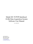
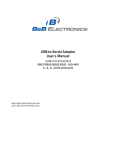
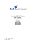
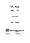
1
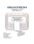
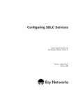
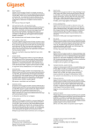
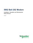
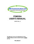
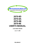
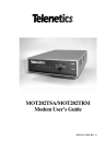
Telenetics 2185 Digital Bridge User Guide Notice 2001 Telenetics Corporation 25111 Arctic Ocean Lake Forest, California 92630 (949) 455-4000 All rights reserved Printed in U.S.A. Proprietary Material Information and software in this document are proprietary to Telenetics Corporation (or its Suppliers) and without the express prior permission of an officer of Telenetics Corporation, may not be copied, reproduced, disclosed to others, published, or used, in whole or in part, for any purpose other than that for which it is being made available. This document is for information purposes only and is subject to change without notice. Warning This equipment generates, uses and can radiate radio frequency energy and if not installed and used in accordance with the instruction manual, may cause interference to radio communications. It has been tested and found to comply with the limits for a Class A computing device in accordance with the specifications in Subpart J of Part 15 of FCC rules, which are designed to provide reasonable protection against such interference in a commercial environment. Operation of this equipment in a residential area is likely to cause interference; in which case the user, at his own or her own expense, is required to take whatever measures may be required to correct the interference. Notice (cont’d) Warning This equipment does not exceed the Class A limits for radio noise interference emissions from digital apparatus as specified in the radio interference regulations of the Canadian Department of Communications. Contents Chapter 1, Introduction Introduction ..................................................................................... 1-1 2185 FEATURES ............................................................................ 1-1 Data Interface ............................................................................ 1-1 Main Channel Broadcast ........................................................... 1-2 Subchannel Contention .............................................................. 1-2 Synchronous Data Retiming Buffer .......................................... 1-2 Anti-Streaming .......................................................................... 1-3 APPLICATIONS ............................................................................. 1-3 Port-Sharing Mode .................................................................... 1-4 Modem-Sharing Mode ............................................................... 1-5 Co-Located Terminals ............................................................... 1-6 Cascading the 2185 .................................................................... 1-6 Specifications .................................................................................. 1-9 Chapter 2, Installation INTRODUCTION .......................................................................... 2-1 CUSTOMER RESPONSIBILITIES ............................................... 2-1 Site Selection and Preparation ........................................................ 2-1 Unpacking ....................................................................................... 2-2 Packing Materials ...................................................................... 2-2 Equipment Supplied .................................................................. 2-2 Damage/Material Shortages ...................................................... 2-2 Installation Procedure ..................................................................... 2-3 Equipment Assembly ................................................................. 2-3 Installation Tools Required ........................................................ 2-3 Mechanical Installation ............................................................. 2-3 Cabling ...................................................................................... 2-3 Chapter 3, Operation and Configuration Introduction ..................................................................................... 3-1 Operating Controls and Indicators .................................................. 3-1 Function Switches ........................................................................... 3-3 Function Switch One ................................................................. 3-3 Function Switch Two ................................................................. 3-4 Function Switch Three ............................................................ 3-14 LED Indicators .............................................................................. 3-14 Configuration Examples ............................................................... 3-14 Digital Bridging Application Example .................................... 3-15 Leased-Line Backup Application Example ............................. 3-18 Multimaster Multidrop Application Example ......................... 3-22 Main Power Connection ............................................................... 3-26 Operation ...................................................................................... 3-28 Power-Down Procedure ................................................................ 3-28 Telenetics 2185 Chapter 4, Operation and Configuration Maintenance Philosophy ................................................................. 4-1 Preventive Maintenance ............................................................. 4-1 Corrective Maintenance ............................................................. 4-1 Recovery from Anti-Streaming Alarm Condition ..................... 4-1 Returning Defective Equipment for Repair .................................... 4-2 General Packing Information ..................................................... 4-2 Installations in the USA ............................................................. 4-2 Installations Outside the USA or Canada .................................. 4-3 Chapter 5, Ordering Information Introduction ..................................................................................... 5-1 Ordering Information ................................................................. 5-1 Glossary Index vi Chapter 1 Introduction INTRODUCTION Your Telenetics 2185 is a digital bridge that can connect up to five subchannel devices to a single main channel device. Sharing computer and communications resources through a 2185 can achieve significant savings in hardware and line costs. The 2185 is a versatile unit that can be used in both port-sharing and modem-sharing applications. The main channel and each of the five subchannels are individually configurable as either EIA 232-D Data Terminal Equipment (DTE) or Data Circuit-terminating Equipment (DCE). Data received on the main channel is broadcast simultaneously to the subchannels. Subchannels contend for one-at-a-time access to the main channel. 2185 FEATURES To ensure trouble-free operation and allow for network growth you 2185 has a number of impressive built-in features including subchannel contention, anti-streaming, and a synchronous data retiming buffer. Data Interface To virtually guarantee you are able to connect your equipment to the 2185, all data interfaces (main channel and five subchannels) are EIA 232-D compatible. They can be individually configured as DTE or DCE via front-panel-mounted DIP switches. All connections to the 2185 are made via straight-through cables. 1-1 Telenetics 2185 Main Channel Broadcast Data received on the main channel is broadcast to all subchannels. In synchronous operation, the corresponding clock is also broadcast. DSR and DCD are sent to all subchannel DTE devices, and DTR and RTS to all subchannel DCE devices. Subchannel Contention Subchannels contend for use of the main channel to send data to the CPU, controller, or other device. If more than one subchannels attempts to gain access to the main channel at one time, the 2185 selects one subchannel and blocks data from all others. Subchannel contention reduces the garbling of data during network failure conditions. Either of two modes of contention may be selected: data contention or control signal contention. In the data contention mode, subchannel devices contend for access to the main channel by sending data (beginning with a space bit). The selected subchannel is disconnected from the main channel after 16 consecutive mark bits are detected. In the control signal contention mode, subchannel devices contend by raising control signal RTS if the device is a DTE, or control signal DCD if the device is a DCE. The 2185 returns CTS to a selected subchannel DTE device. The selected subchannel disconnects from the main channel when the subchannel device drops RTS or DCD. Synchronous Data Retiming Buffer In synchronous operation, the 2185 uses an internal buffer to retime inbound subchannel data to the main channel clock. To allow for uninterrupted service, this buffer compensates for phase differences between the subchannel and main channel clocks and can absorb clock jitter and minor differences in frequency. Without the buffer the differences in 1-2 Telenetics 2185 phase, frequency, and the presence of jitter could cause the subchannel and the main channel to lose synchronization. If synchronization is lost, data errors occur and transmission fails. When the 2185 is configured for asynchronous operation, the retiming buffer is bypassed. Anti-Streaming Anti-streaming protects the network from becoming jammed if one of the subchannel devices fails. If the subchannel remains active for longer than the anti-streaming time-out period, nominally 25 seconds, it automatically is disabled and its alarm LED indicator lamp illuminates. When a subchannel is disabled, it disconnects from the main channel and is not permitted to contend for the main channel again until after it is re-enabled. Before attempting to re-enable the subchannel device, it must be inactive for approximately 1.5 seconds. The alarm LED then extinguishes and the subchannel can again contend for the main channel. You may disable anti-streaming with a front panel switch. APPLICATIONS The 2185 is used in multipoint networks made up of a controller and polled terminals. The controller inserts terminal address codes and the terminals must be able to respond to their own address code. The 2185 arbitrates if two or more terminals try to transmit simultaneously. When considering possible applications for your 2185, remember the following points: • The 2185 can transmit in either asynchronous or synchronous format, but all devices in the network must use the same format. • All devices must operate at the same data rate. When the main channel is connected to a DCE device, the transmit and receive clocks may be at different rates, but all devices have common transmit clocks and common receive clocks. 1-3 Telenetics 2185 • When operating with control signal contention, the 2185 is transparent to the data stream. • When operating with data contention, subchannel data must be mark idle and 16 consecutive marks cannot appear in mid-message. The minimum data rate for an external clock is 50 bps. Port-Sharing Mode In the port-sharing mode, the 2185's main channel is connected directly to a CPU or controller port (DTE). Subchannel devices communicate with the 2185 via modem links. Figure 1-1 shows a typical port-sharing application. Figure 1-1. Port-Sharing Application 1-4 Telenetics 2185 Modem-Sharing Mode In the modem-sharing mode, the CPU or controller is at a site remote from the 2185. The 2185's main channel connects to the CPU through a modem link (DCE). Subchannel terminals are connected directly to the 2185. Modem-sharing operation is illustrated in Figure 1-2. Figure 1-2. Modem-Sharing Application 1-5 Telenetics 2185 Co-Located Terminals Any combination of subchannel DTE devices and subchannel DCE devices is possible. For example, local subchannel terminals can be colocated with modes that communicate with devices at remote sites. Figure 1-3 shows an example of co-located terminals in the port-sharing mode. Co-location of ports and modems is also possible in the modemsharing mode. Figure 1-3. Co-Located Terminals Application Cascading the 2185 The 2185 can be cascaded to increase the number of channels connected to the main channel controller. Cascading is accomplished by connecting the main channel of one unit to a subchannel of another unit. See Figure 1-4. 1-6 Telenetics 2185 Figure 1-4. Local Cascading Application 1-7 Telenetics 2185 Two or more of the 2185s can be located at one site as shown in Figure 1-4. Alternatively, the units may be located at sites remote from each other, and connect via modems. See Figure 1-5. Figure 1-5. Remote Cascading Application 1-8 Telenetics 2185 SPECIFICATIONS Table 1-1 summarizes 2185 specifications. Table 1-1. 2185 Specifications Data Rates Internally Generated 75,1200,2400,4800,7200,9600,14400,1920 0, bps (all ± 0.01%) Externally Clocked Any rate up to 20000 bps Data Format Asynchronous or Synchronous Synchronous Retiming Buffer Elastic storage buffer with ± 4-bit capacity Subchannel to Main Channel Contention Control Signal (RTS or DCD) or Data Contention Data Interface Characteristics Compatible with EIA 232-D and CCITT V.24 Anti-Streaming Timers Disable Timer 25 seconds (+2.3/–1.1 seconds) Re-Enable Timer 1.5 seconds (+0.20/–0.01 seconds) Physical Characteristics Height 2.75 in (6.69 cm) Width 8.54 in. (21.69 cm) Depth 16.00 in. (40.64 cm) Weight 5.00 lb (2.3 kg) Environmental Characteristics Operating Temperature 32°F to 122°F (0°C to 50°C) Humidity 95% maximum (non-condensing) Altitude Sea Level to 8000 ft (2440m) AC Power Requirements 90 V ac to 132 V ac or 180 V ac to 264 V ac 47 to 63 Hz 10 Watts max. power consumption 1-9 Telenetics 2185 1-10 Chapter 2 Installation INTRODUCTION This chapter contains the information you need to install you Telenetics 2185. CUSTOMER RESPONSIBILITIES After delivery of your equipment and before installation, you are responsible for moving it to the installation site, unpacking and checking it for material shortages and/or damage, which may have occurred during shipment. SITE SELECTION AND PREPARATION Ensure that the area where your Telenetics 2185 is to be installed is clean and free from extremes of temperature, humidity, shock, and vibration.The site must meet the physical, environmental and power requirements listed in Table 1-2 - 2185 Specifications. Install the 2185 within 5 feet (1.5 meters) of a grounded ac outlet capable of furnishing the required primary power (115 V ac or 230 V ac).The unit must also be located within 50 feet (15.2 meters) of the terminal ports and/or modems to be connected to it.At least 5 inches (12.7 cm) clearance at the rear of the unit is needed for interface cabling. 2-1 Telenetics 2185 UNPACKING Packing Materials Your 2185 is wrapped in re-usable, shock-absorbent packing material. Telenetics recommends that you keep this packing material and the shipping carton in case the unit must be stored, shipped, or returned to Telenetics for service. Check the contents of the package against the packing list for material shortages and inspect the unit, for physical damage, which may have occurred in shipment.If there is any damage to the equipment, contact the shipping agent immediately. Equipment Supplied The contents of the shipping carton are as follows: • One Telenetics 2185 • One transformer • One Telenetics 2185 Operator's Guide Damage/Material Shortages Direct any additional questions about damage or missing parts to your nearest Telenetics representative, or contact: Telenetics Corporation 25111 Arctic Ocean Lake Forest, California 92630 (949) 455-4000 Web site: htttp://www.telenetics.com 2-2 Telenetics 2185 INSTALLATION PROCEDURE Equipment Assembly The 2185 is shipped as a completely assembled unit with the printed circuit board and power supply sub-assemblies already installed.No further assembly is required. Installation Tools Required The only tool required is a small slot screwdriver to tighten the screws securing the interface cable connectors to the connectors on the unit's rear panel. Mechanical Installation The 2185 is a “tabletop” unit.No provisions are made for securing the unit to any surface. Cabling All external connections to the 2185 are made via EIA 232-D, 25-pin, connectors located on the rear panel (see Figure 2-1) and their associated straight-through cables.There are six connectors, one for the main channel, and one for each subchannel. In Figure 2-1: Port 0 = Main Channel Port 2 = Subchannel 2 Port 0 = Subchannel 4 Port 1 = Subchannel 1 Port 3 = Subchannel 3 Port 1 = Subchannel 5 2-3 PORT 5 PORT 4 PORT 3 PORT 2 PORT 1 PORT 0 Figure 2-1. Rear Panel Assembly Note: The 2185 may have its main channel or any subchannel configured as DCE or DTE.Any necessary signal crossovers are performed internally. Telenetics 2185 Note: The 2185 may have its main channel or any subchannel configured as DCE or DTE. Any necessary signal crossovers are performed internally. Figure 2-2. Straight-Through Cable Interface Figure 2-2 shows the straight-through cable signal interface. Be sure to tighten all connectors securely to ensure good mechanical connection, and to assure the integrity of the cable shield. 2-5 Telenetics 2185 2-6 Chapter 3 Operation and Configuration INTRODUCTION This chapter describes the 2185 operating controls and indicators, how to configure and operate your 2185 using these operating controls, and how to power-up and power-down the unit. Once configured, your 2185 operates unattended, without operator intervention. Occasional monitoring of the LED status indicators is recommended. OPERATING CONTROLS AND INDICATORS The 14 LED indicator lamps used to monitor operating status on the 2185 are visible from the front of the unit through windows in the swing-down front door (see Figure 3-1). All operating controls and switches on the 2185 are readily accessible when you open the front door (see Figure 3-2). Figure 3-1. Front View (Door Closed) 3-1 Telenetics 2185 Figure 3-2. 2185 Inside Front Panel 3-2 Telenetics 2185 FUNCTION SWITCHES The front-panel-mounted controls consist of three Dual In-line Package (DIP) function switches. Switch banks one and two contain eight individual switches and switch three contains six individual switches. The role of function switches one, two and three is summarized in Tables 3-1 through 3-5. The following paragraphs describe these functions in more detail. Function Switch One Function switch one is an eight-segment DIP switch used to enable or disable each of the five subchannels. It is also used to set the clock data rate. Switch segments 1-1 through 1-5 Disable/Enable subchannels one through five respectively. Their operation is described as follows: • Switch 1-n is set to up position to disable Subchannel n • Switch 1-n is set to the down position to enable Subchannel n, where n = 1 - 5 Subchannels may be disabled to prevent them from contending for the main channel. The main channel broadcasts to all subchannels, whether the subchannels are enabled or disabled. Unused subchannels should be disabled (i. e., appropriate switch set to the up position). Table 3-1. Enabling/Disabling Subchannels Switch Up Down 1-1 Disable Subchannel 1 Enable Subchannel 1 1-2 Disable Subchannel 2 Enable Subchannel 2 1-3 Disable Subchannel 3 Enable Subchannel 3 1-4 Disable Subchannel 4 Enable Subchannel 4 1-5 Disable Subchannel 5 Enable Subchannel 5 3-3 Telenetics 2185 Switch segments 1-6 to 1-8 are used to set the data rate on the 2185. See Table 3-2 for information on setting these switches. Table 3-2. Data Rate Selection Using Switch Segments 1-6 to 1-8 Clock Data Rate (bps) Set 1-6 to: Set 1-7 to: Set 1-8 to: 75 Up Up Up 1200 Up Up Down 2400 Up Down Up 4800 Up Down Down 7200 Down Up Up 9600 Down Up Down 14400 Down Down Up 19200 Down Down Down Function Switch Two Function switch two is an eight-segment DIP switch used to set controlsignal contention, select synchronous or asynchronous data format, select or bypass the retiming buffer, enable or disable anti-streaming, set the clock signal routing, set main channel RTS on DCD transparent or on, and set main channel inbound CTS transparent or on. Table 3-3. Function Switch Two Summary Function Switch Switch Position Function 2-1 Up Down Sets Control Signal Contention Sets Data Contention 2-2 Up Down Sets synchronous data format Sets asynchronous data format 2-3 Up Down Synchronous Data Retiming Buffer in circuit Synchronous Data Retiming Buffer bypassed 2-4 Up Down Disables Anti-Streaming Enables Anti-Streaming 2-5 and 2-6 See Table 3-4 These two switches work together to set Clock Routing 3-4 Telenetics 2185 Table 3-3. Function Switch Two Summary Function Switch Switch Position Function 2-7 Up Down Sets main channel RTS or DCD transparent Straps main channel RTS or DCD ON 2-8 Up Down Straps main channel inbound CTS ON Sets main channel inbound CTS transparent In certain synchronous configurations, the internal clock generator is not used and the data rate is determined by the selected external clock source. (For details, refer to the section on function switch segments 2-5 and 2-6 - Clock Routing.) The internal clock generator is also used in asynchronous applications when Data Contention is selected. Switch Segment 2-1 — Contention Mode • Switch 2-1 set to up position – Control Signal Contention • Switch 2-1 set to down position – Data Contention In applications where the subchannel devices toggle control signals, set this switch to the up position for Control Signal Contention. Where active control signals are not provided, set to the down position for Data Contention. This selects the RTS or DCD control signal for contention, depending on whether the subchannel is configured as a DTE or DCE. When Data Contention mode is selected, switch segments 2-7 and/or 28 must be strapped ON. Switch Segment 2-2 — Data Format • Switch 2-2 set to up position – Synchronous format • Switch 2-2 set to down position – Asynchronous format Set this switch to the up position for Bisynchronous or HDLC applications (synchronous operation). When set to the down position, (asynchronous operation selected), the retiming buffer is bypassed. Switch Segment 2-3 — Synchronous Data Retiming Buffer • Switch 2-3 set to up position – Normal • Switch 2-3 set to down position – Buffer bypassed When the 2185 is configured for asynchronous data format (function switch 2-2 is set to the down position), that switch may be ignored. 3-5 Telenetics 2185 With synchronous data transmission, the data retiming buffer must be used except when all subchannels are connected to DTE devices. The data retiming buffer may then be bypassed to permit passing Bisynchronous multiple messages in Data Contention mode. Switch Segment 2-4 — Anti-Streaming Enable/Disable • Switch 2-4 set to up position – Anti-Streaming Disabled • Switch 2-4 set to down position – Anti-Streaming Enabled Enabling Anti-Streaming limits a subchannel message to 25 seconds. If subchannel messages are greater than 23 seconds in length, anti-streaming should be disabled. Switch Segment 2-5 and 2-6 — Clock Routing When the 2185 is configured for asynchronous data format switches 2-5 and 2-6 are ignored. If the 2185 is configured for synchronous data format, switches 2-5 and 2-6 are used to select the master clock source. The network may be clocked from the main channel device, the 2185's internal clock, or the Subchannel 1 device if it is a DCE device. Switch segments 2-5 and 2-6 much be set as described in Table 3-4. Note that only the configurations listed in Table 3-2 are valid; all other combinations are illegal and result in errors. When the 2185 is configured for subchannel 1 DCE clock timing (Figures 3-7 and 3-8), the 2185 uses the Receive Clock signal of the DCE for timing. Should DCE's clock signal fail, the Clock Alarm on the 2185 illuminates and the 2185 reverts to its own internal oscillator. Table 3-4. Clock Routing Configurations Fig Ref. 3-3/4 Clock Source Subchannel 1 Set 2-5 to Set 2-6 to Main Channel X Up Down 3-5/6 Internal X Down Down 3-7/8 Sub Ch. 1 DCE Down Up Note: X = does not matter 3-6 Telenetics 2185 Switch Segment 2-7 — Main Channel RTS/DCD Strapping • Switch 2-7 set to up position – RTS/DCD transparent • Switch 2-7 set to down position – RTS/DCD strapped ON When switch segment 2-7 is set for transparent RTS/DCD operation, the main channel outbound RTS or DCD signal is ON only when a subchannel is active. When switch segment 2-7 is set to the down position, the main channel RTS/DCD is strapped ON at all times. Switch Segment 2-8 — Main Channel CTS Strapping • Switch 2-8 set to up position –CTS strapped ON • Switch 2-8 set to down position – CTS transparent This switch is ignored when the main channel is connected to a DTE device. If the 2185 is set for CTS strapped ON, CTS is sent to a contending subchannel DTE device as soon as the main channel is available. When switch segment 2-8 is set for transparent CTS, the CTS signal is not set to a contending subchannel DTE device until CTS has been received ON from the main channel device. See Figures 3-3 through 3-8. 3-7 Telenetics 2185 Figure 3-3. External Clock Reference with Main Channel DTE 3-8 Telenetics 2185 Figure 3-4. External Clock Reference with Main Channel DCE 3-9 Telenetics 2185 Figure 3-5. Internal Clock Reference with Main Channel DTE 3-10 Telenetics 2185 Figure 3-6. Internal Clock Reference with Main Channel DCE 3-11 Telenetics 2185 Figure 3-7. Subchannel 1 DCE Clock Reference with Main Channel DTE 3-12 Telenetics 2185 Figure 3-8. Subchannel 1 DCE Clock Reference with Main Channel DCE 3-13 Telenetics 2185 Function Switch Three Function switch three is a six-segment DIP switch used to configure the data interfaces for each channel. Set to Up (DTE) if the channel is connected to a DTE-type device such as a CPU port or a terminal (this configures the 2185 interface as Data Circuit-terminating Equipment - DCE). Set down (DCE) if the channel is connected to a DCE-type device such as a modem (this configures the 2185 interface as Data Terminal Equipment - DTE). Table 3-5. DTE/DCE Optioning Position Sw3-1 Up Down Sw3-2 Sw3-3 Sw3-4 Sw3-5 Sw3-6 Main Ch. Sch. 1 DTE DTE Sch. 2 DTE Sch. 3 DTE Sch. 4 DTE Sch. 5 DTE Main Ch. Sch. 1 DCE DCE Sch. 2 DCE Sch. 3 DCE Sch. 4 DCE Sch. 5 DCE LED INDICATORS Table 3-6 lists the functions of the LED status indicators. Under normal operating conditions, none of the alarm indicators is illuminated. Refer to the section entitled Recovery From Anti-Streaming Alarm Condition in Chapter 4 - Maintenance for the procedure to handle alarms. CONFIGURATION EXAMPLES The following examples show how you might option your 2185 for a variety of configurations. These examples are provided to demonstrate the versatility of the 2185. Your specific application, and thus product configuration, may differ from those described here. For an explanation of the various switches, refer to the function switch descriptions in the previous sections. 3-14 Telenetics 2185 Digital Bridging Application Example One of the most common applications for your 2185 is as a digital bridge. In this instance, a 2185 is used to connect a large number of local and remote asynchronous terminals to a mainframe computer at a central site. Figure 3-9 shows this application. In this application, the main channel of the 2185 connects to a host computer through a front-end processor. The data rate is 9. 6 kbps and the format is synchronous. Since the main channel is connected to a DTEtype device, the main channel on the 2185 is set to DTE. All three subchannels are set to operate at 9. 6 kbps, as they must be the same as the main channel. Subchannels one and two are set to DTE, since they are connected directly to controllers. Subchannel three is set to DCE, as it connects to a modem. The following charts show the correct switch settings for this particular application. 3-15 Telenetics 2185 Figure 3-9. 2185 Digital Bridging Application 3-16 Telenetics 2185 Table 3-6. Switch One Switch Segment Setting Reason 1-1 Down Enable Subchannel 1 1-2 Down Enable Subchannel 2 1-3 Down Enable Subchannel 3 1-4 Up Disable Subchannel 4 1-5 Up Disable Subchannel 5 1-6 Down 1-7 Up The settings of these three switches set the data rate (9. 6 kpbs) 1-8 Down Table 3-7. Switch Two Switch Segment Setting Reason 2-1 Up Control Signal Contention 2-2 Up Synchronous operation 2-3 Up Retiming Buffer on 2-4 XX Depends on line conditions (typically set to down) 2-5 Down Internal clock source 2-6 Down 2-7 Down RTS/DCD on all the time 2-8 XX Doesn't care (Main Ch DTE) 3-17 Telenetics 2185 Table 3-8. Switch Three Switch Segment Setting Reason 3-1 Up Main Channel connection to DTE 3-2 Up Subchannel one connection to DTE 3-3 Up Subchannel two connection to DTE 3-4 Down Subchannel three connection to DCE 3-5 XX Subchannel four not used 3-6 XX Subchannel five not used Leased-Line Backup Application Example Another common application example for your 2185 is the Leased-Line Backup application. In this example, the 2185 is again used to connect a mainframe to remote users. The primary connection is through a digital network via DSUs (Digital Service Units). The backup route is through leased-lines via dial modems. Figure 3-10 shows this application. 3-18 Telenetics 2185 Figure 3-10. 2185 Leased-Line Backup Application 3-19 Telenetics 2185 In this application the main channel of 2185 A is connected to a host computer through a front-end processor. The data rate is 9. 6 kbps and the format is synchronous. Since the main channel is connected to a DTE type device the main channel on 2185 A is set to DTE. Two subchannels are connected to 2185 B through two networks. One rout is through a digital network and the backup route is through a common telephone network. Subchannels one and two of both 2185 A and 2185 B are set to DCE as that is the type of device to which they are connected. The main channel of 2185 B is set to DTE since it is connected to the controller. Clocking in this network is derived from the DSU connected to Subchannel One. The following tables show the correct switch settings for this particular application and apply to both 2185s. Table 3-9. Switch One Switch Segment 1-1 Setting Reason Down Enable Subchannel 1 1-2 Down Enable Subchannel 2 1-3 Up Disable Subchannel 3 1-4 Up Disable Subchannel 4 1-5 Up Disable Subchannel 5 1-6 Down 1-7 Up The settings of these three switches set the data rate (9. 6 kpbs) 1-8 Down 3-20 Telenetics 2185 Table 3-10. Switch Two Switch Segment Setting Reason 2-1 Down Data Contention 2-2 Up Synchronous operation 2-3 Up Retiming Buffer on 2-4 XX Depends on line conditions 2-5 Down Clock source from 2-6 Up Subchannel One DSU 2-7 Down RTS/DCD on all the time 2-8 XX Doesn't matter (Main Ch DTE) Table 3-11. Switch Three Switch Segment Setting Reason 3-1 Up Main Channel connection to DTE 3-2 Down Subchannel one connection to DCE 3-3 Down Subchannel two connection to DCE 3-4 XX Subchannel three not used 3-5 XX Subchannel four not used 3-6 XX Subchannel five not used 3-21 Telenetics 2185 Multimaster Multidrop Application Example In this application, 2185s are used to provide a link between remote users and two mainframes, with the second mainframe serving as the backup for the first. Figure 3-11 shows this application. SCH. 4 Figure 3-11. Multimaster Multidrop Application 3-22 Telenetics 2185 In this application, the main channel of both 2185 A and 2185 B are connected via a straight-through cable with the 2185 A main channel set to DTE and the 2185 B main channel set to DCE. The data rate is 1.2 kpbs asynchronous so clocking is not an issue. Subchannel one of 2185 A is connected directly to the local host computer and is set to DTE. Subchannel two is connected via a modem link to the backup computer installation and is set to DCE. All five subchannels of 2185 B are connected to external devices with subchannels one, two, and four set to DTE and subchannels three and five set to DCE. The following tables show the switch settings for 2185 A first and then for 2185 B. Table 3-12. Switch One Settings – 2185 A Switch Segment 1-1 Setting Down Reason Enable Subchannel 1 1-2 Down Enable Subchannel 2 1-3 Up Disable Subchanel 3 1-4 Up Disable Subchannel 4 1-5 Up Disable Subchannel 5 1-6 Up 1-7 Up The settings of these three switches set the data rate (9. 6 kpbs) 1-8 Down 3-23 Telenetics 2185 Table 3-13. Switch Two Settings – 2185 A Switch Segment Setting Reason 2-1 Up Control Signal Contention 2-2 Down Asynchronous operation 2-3 XX Does not matter; on for sync only 2-4 XX Depends on line conditions 2-5 XX 2-6 XX Does not matter, since unit is set for async. operation 2-7 Down RTS/DCD on all the time 2-8 XX Does not matter (Main Ch DTE) Table 3-14. Switch Three Settings – 2185 A Switch Segment Setting Reason 3-1 Up Main Channel connection to DTE 3-2 Up Subchannel one connection to DTE 3-3 Down Subchannel two connection to DCE 3-4 XX Subchannel three not used 3-5 XX Subchannel four not used 3-6 XX Subchannel five not used Table 3-15. Switch One Settings – 2185 B Switch Segment Setting Reason 1-1 Down Enable Subchannel 1 1-2 Down Enable Subchannel 2 1-3 Down Enable Subchannel 3 1-4 Down Enable Subchannel 4 1-5 Down Enable Subchannel 5 1-6 Up 1-7 Up The settings of these three switches set the data rate (1. 2 kpbs) 1-8 Down 3-24 Telenetics 2185 Table 3-16. Switch Two Settings – 2185 B Switch Segment 2-1 Setting Down Reason Data Contention 2-2 Down Asynchronous operation 2-3 XX Does not matter, since the unit is on for sync only 2-4 XX Depends on line conditions 2-5 XX 2-6 XX Doesn't matter, since the unit is set for async. operation 2-7 Down RTS/DCD on all the time 2-8 Up CTS on all the time Table 3-17. Switch Three Settings – 2185 B Switch Setting Reason 3-1 Down Main Channel connection to DCE 3-2 Up Subchannel one connection to DTE 3-3 Up Subchannel two connection to DTE 3-4 Down Subchannel three connection to DCE 3-5 Up Subchannel four connection to DTE 3-6 Down Subchannel five connection to DCE 3-25 Telenetics 2185 Table 3-18. LED Status Indicator Functions LED Indicator Function SYSTEM POWER Illuminates when the unit powers up CLOCK FAIL ALARM Illuminates when the 2185 derives its clock signal from Subchannel 1 DCE and the clock input fails MAIN CHANNEL DATA Illuminates when the main channel inbound data is a SPACE RDY (Ready) Illuminates when the main channel inbound DSR or DTR is ON SUBCHANNELS 1 TO 5 ACTIVE Illuminates when the subchannel indicated gains access to the main channel ALARM Alarm illuminates for a channel that Is automatically disabled by the anti-streaming timer. Under normal operating conditions, all of these LED indicator lamps should be extinguished. MAIN POWER CONNECTION 115 Volt Models - 115V ac models use a wall-mount transformer (Product Code 28410?) equipped with a North American plug. (An appropriate adapter may be used in other countries supplying 115V ac line voltage.) This supply allows operation on 100 V ac systems. 230 Volt Models - 230 V ac models use a desktop transformer (Product Code 28413?) equipped with a CEE7/7 plug. (An appropriate adapter may be used in other countries supplying 230 V ac line voltage.) Others - If the above power arrangements are not applicable to your country, the 2185 requires a fused power supply: 24 V ac ± 10%, 50 to 60 Hz, center-tapped, at 0. 2A (order Cable Product Code 28415?). 3-26 Telenetics 2185 Alternative power supplies that were not approved at the time of this publication may be available; consult your local distributor for special requirements. Figure 3-12. 2185 - Power Connection 3-27 Telenetics 2185 OPERATION Once you successfully power-up your 2185, it is fully operational and does not require any further initialization procedures. Once configured, your 2185 operates unattended without operator intervention. Occasional monitoring of the LED status indicators is recommended. POWER-DOWN PROCEDURE Proceed as follows to power-down your 2185. Remove the ac power cord from the primary ac power source. Your 2185 retains its previous configuration when powered-up again. 3-28 Chapter 4 Operation and Configuration MAINTENANCE PHILOSOPHY Preventive Maintenance There is no preventive maintenance necessary on your Telenetics 2185 other than the occasional removal of dust that a have settled on the unit. Use a soft cloth to remove dust that may have built up on the outside of the unit. Corrective Maintenance There are no user-repairable components in the 2185. The 2185 is designed to provide maximum up-time. In the event that repairs are required, Telenetics Corporation or an authorized Telenetics representative should perform them. Field repair of defective units or modules is not recommended. You can reach Telenetics by calling (949) 455-4000 or through our Web site at http://www.telenetics.com. Recovery from Anti-Streaming Alarm Condition If a subchannel anti-streaming alarm indication occurs, disable the affected channel using the appropriate FUNCTION Switch (1-1 to 1-5; refer to Chapter 3 - Operation). Correct the fault in the subchannel device and restore it to the network by re-enabling the subchannel. 4-1 Telenetics 2185 If all equipment in the network is functioning properly and anti-streaming alarms are occurring, the probable cause is that the subchannel devices are sending valid messages longer than 23 seconds. If this is the case, disable anti-streaming. RETURNING DEFECTIVE EQUIPMENT FOR REPAIR General Packing Information When returning defective equipment to Telenetics or an authorized Telenetics representative for repair, pack the equipment using the following guidelines. 1. Do not mark the equipment. Enclose a shipping list identifying each item by serial/part number. Defective units should have tags attached indicating product name and description, product serial number, customer order number, the malfunction or failure indication, and the return address. 2. Wherever possible, re-use the original packing material and shipping container. 3. Secure movable and exposed parts before shipment so that they don't come loose in shipment and cause or sustain damage. 4. Materials that are abrasive, flake-off or produce dust must not be used for cushioning. Installations in the USA When returning defective equipment to Telenetics for factory repair, customers in the USA should contact the Telenetics Return Services Coordinator, at the following number, for return authorization and instructions: Tel: (949) 455-4000 Web site: http://www.telenetics.com 4-2 Telenetics 2185 When contacting Telenetics, you receive a Telenetics Return Material Authorization (RMA) Control Number. This RMA Control Number should be clearly marked on the return equipment shipping container(s) for easy identification and faster service. The RMA Control Number is a shipment control tool and does not affect the provisions of a Sales or Lease agreement. You need to supply the following information for each piece of equipment returned: • Product Name and Description • Product Serial Number • Customer Order Number • Failure Symptoms When possible, include a purchase-order number for billing purposes. After packaging the defective materials, ship them prepaid to: Telenetics Corporation 25111 Arctic Ocean Lake Forest, California 92630 Installations Outside the USA or Canada Customers outside the USA and Canada should return defective units to Telenetics Corporation at the above address. Before shipping the unit, obtain a Return Authorization Number and the Return Procedure from Telenetics Corporation. The Return Procedure outlines the appropriate Canadian Customs documentation and information that must accompany each return shipment. 4-3 Telenetics 2185 4-4 Chapter 5 Ordering Information INTRODUCTION This chapter provides Telenetics product and ordering information for the 2185. Ordering Information Table 5-1 lists Telenetics 2185 products for and accessories. Any of the items listed may be ordered from your authorized Telenetics representative. Table 5-1. Telenetics Ordering Information Item Product Code Description 28500 115V ac, 50/60 Hz Standalone Units 2185 2185 28501 230V ac, 50/60 Hz 2185 28502 14V ac (no transformer) 28504 5 channel nest card 28506 2185 Enclosure 28410 115 V ac power supply 28413 230 V ac power supply 28510 User’s Installation/Operation manual 2185 Components Documentation Operator's Guide 5-1 Telenetics 2185 5-2 Glossary This glossary defines terms used in the 2185 Operator's Guide. ACTIVE LED indicator lamp that illuminates when the subchannel indicated gains access to the main channel. ALARM LED indicator lamp that illuminates when the antistreaming timer automatically disables a subchannel. Anti-Streaming Scheme that protects the network from becoming jammed should one of the subchannel devices fail. If the selected subchannel remains active for longer than the anti-streaming time-out period it's automatically disabled and its alarm LED indicator lights up. Anti-Streaming Time-out Nominally 25 seconds in the 2185. Cascading The 2185 may be cascaded to increase the number of channels that can be connected to the main channel controller. Cascading is accomplished by connecting the main channel of one unit to a subchannel of another unit. The cascaded units may be located at one site or the units may be located at sites remote from each other, and be connected through modems. Co-Located Terminals Using the 2185, any combination of subchannel DTE devices and subchannel DCE devices is possible. For example, local subchannel terminals can be co-located with modems that communicate with devices at remote sites. Co-location of ports and modems can be performed in both port-sharing and modem-sharing operation modes. Contention In communications, the case where multiple users vie for the right to use a transmission channel on a first-come first-serve basis, whether a PBX circuit, a computer port, or a time slot within a multiplexed facility. Glossary-1 Telenetics 2185 Controller Device responsible for polling terminals and routing messages in a multipoint environment. Control Signal Contention Mode Subchannels contend for use of the main channel to send data to the CPU or controller. In the control signal contention mode, subchannel devices contend by raising control signal RTS if the device is a DTE, or control signal DCD if the device is a DCE. The 2185 DSD returns CTS to a selected subchannel device. The selected subchannel disconnects from the main channel when the subchannel device drops RTS or DCD. DATA LED indicator lamp that illuminates when the main channel inbound data is a SPACE. Data Contention Subchannels contend for use of the main channel to send data to the CPU or controller. In the data contention mode, a subchannel contends for access to the main channel by sending data (beginning with a space bit). The selected subchannel disconnects from the main channel after 16 consecutive mark bits are detected. Modem-Sharing In the modem-sharing mode, the CPU or controller is at a site remote from the 2185. The 2185's main channel connects to the CPU through a modem link (DCE). Subchannel terminals are connected directly to the 2185 DSD. Multipoint A communications arrangement where multiple devices share a common transmission channel, though only one device may transmit at a time. Such networks usually require some kind of polling mechanism, which is under the control of a master station, to ensure that only one device transmits data at a time. Also known as a multidrop network. Port Physical point of access into a computer, a network, or other electronic device. Port-Sharing In the port-sharing mode, the 2185's main channel is connected directly to a CPU or controller port (DTE). Subchannel devices communicate with the 2185 DSD via modem links. Glossary-2 Telenetics 2185 RDY Ready. LED indicator lamp that illuminates when the main channel inbound DSR or DTR is ON. Straight-Through Cable Cable terminated with 25-pin EIA connector at each end. Connections are made on a pin-to-pin basis. See Figure 2-2. Subchannel Contention Subchannels contend for use of the main channel to send data to the CPU or controller. If more than one subchannel tries to access the main channel at one time, the 2185 selects one subchannel and blocks data from all the others. You may select either of two contention modes — either data contention or control signal contention. Synchronous Retiming Buffer When operating in a synchronous data environment, the 2185 uses an internal ±4-bit buffer to retime inbound subchannel data to the main channel clock. The buffer compensates for phase differences between the subchannel and main channel clocks and can absorb clock jitter and minor differences in frequency.When the 2185 is configured for asynchronous operation, the retiming buffer is bypassed. Glossary-3 Telenetics 2185 Glossary-4 Index A Anti-streaming 1-3 Anti-streaming alarm, recovery 4-1 Applications 1-3 cascading the 2185 1-6, 1-8 co-located terminals 1-6 modem-sharing mode 1-5 port-sharing mode 1-4 C Cabling 2-3 Cascading the 2185 1-6, 1-8 Co-located terminals 1-6 configuration defined 3-1 Configuration examples 3-14 digital bridging 3-15 leased-line backup 3-18 multimaster multidrop 3-22 Corrective maintenance 4-1 Customer responsibilities 2-1 D Damage 2-2 Data interface 1-1 Digital bridging application 3-15 E Equipment assembly 2-3 Equipment supplied 2-2 F Features 1-1 anti-streaming 1-3 Data interface 1-1 Main channel broadcast 1-2 subchannel contention 1-2 synchronous data retiming buffer 1-2 Front panel 3-2 Front view 3-1 Function switches 3-3 switch one 3-3 switch three 3-14 switch two 3-4 G General packing information 4-2 Glossary 1 INDEX-1 Index (continued) I Indicators 3-1 Inside front panel 3-2 Installation procedure 2-3 cabling 2-3 equipment assembly 2-3 mechanical 2-3 required tools 2-3 Installation tools 2-3 Installations outside USA or Canada 4-3 USA 4-2 L Leased-line backup application 3-18 LED indicators 3-14 M Main channel broadcast 1-2 Main power connection 3-26 Maintenance corrective 4-1 preventive 4-1 Material shortages 2-2 Mechanical installation 2-3 Modem-sharing mode 1-5 Multimaster multidrop application 3-22 O Operating controls 3-1 Operation 3-28 Ordering information 5-1 P Packing materials 2-2 Port-sharing mode 1-4 Power-down procedure 3-28 Preventive maintenance 4-1 R Recovery from anti-streaming alarm 4-1 Returning defective equipment for repair 4-2 S Site selection 2-1 INDEX-2 Index (continued) Site preparation 2-1 Specifications 1-9 Subchannel contention 1-2 Switches 3-3 switch one 3-3 switch three 3-14 switch two 3-4 Synchronous data retiming buffer 1-2 U Unpacking 2-2 INDEX-3 Index (continued) INDEX-4