1
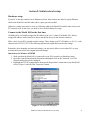
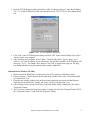
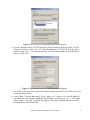
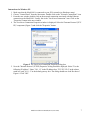
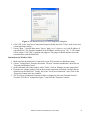
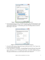
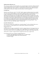
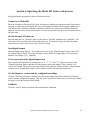
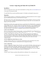
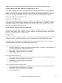
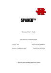
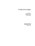
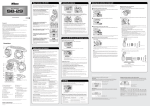
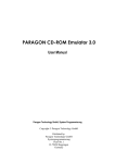
Model 401 TCP/IP-Interfaced
24-Bit Data Acquisition System
Software User Manual
Rev. B (04/10/09)
Lawson Labs, Inc.
Phone: (800) 321-5355
Phone: (610) 725-8800
Fax: (610) 725-9344
www.lawsonlabs.com
[email protected]
Table of Contents
Introduction..............................................................................................................................................1
Section 1: Introduction to TCP/IP..........................................................................................................2
IP address...............................................................................................................................................2
Subnet mask..........................................................................................................................................2
Gateway IP............................................................................................................................................3
Dynamic Host Configuration Protocol (DHCP)...................................................................................3
Media Access Control (MAC) address..................................................................................................3
Section 2: Initial network setup..............................................................................................................4
Hardware setup......................................................................................................................................4
Connect to the Model 401 for the first time..........................................................................................4
Instructions for Windows 95/98/ME................................................................................................4
Instructions for Windows NT/2000..................................................................................................5
Instructions for Windows XP............................................................................................................7
Instructions for Windows Vista........................................................................................................8
Connecting to the Model 401 with a dynamic IP address...................................................................10
Install M40xVB...................................................................................................................................10
Assigning a new IP address.................................................................................................................10
Section 3: Model 401 operating modes.................................................................................................11
Polled mode.........................................................................................................................................11
Scan mode...........................................................................................................................................11
Single-channel scan........................................................................................................................11
Multi-channel scan..........................................................................................................................11
Multi-channel calibration scan.......................................................................................................12
Extended scan.................................................................................................................................12
Extended calibration scan...............................................................................................................12
Triggered start scan.........................................................................................................................12
Section 4: Operating the Model 401 from a web browser..................................................................13
Connect to a Model 401......................................................................................................................13
Set the internal A/D data rate..............................................................................................................13
Send digital output...............................................................................................................................13
Get a conversion and a digital input word...........................................................................................13
Get the firmware version and the configuration settings ...................................................................13
Calibrate..............................................................................................................................................13
Section 5: Operating the Model 401 from M40xVB...........................................................................14
Installation...........................................................................................................................................14
Operation.............................................................................................................................................14
Connect to the Model 401...............................................................................................................14
Get the configuration and the firmware version.............................................................................14
Set the configuration.......................................................................................................................14
Calibrate..........................................................................................................................................14
Set the Model 401 real-time clock (RTC) to match the PC clock..................................................15
Set the internal A/D data rate..........................................................................................................15
Get the channel voltage and the digital input byte.........................................................................15
Set up the scan................................................................................................................................15
Start the scan...................................................................................................................................16
During a scan..................................................................................................................................16
Send digital output..........................................................................................................................17
Plot scans........................................................................................................................................17
Appendix A: Errors................................................................................................................................18
Appendix B: Troubleshooting...............................................................................................................20
Application note: Accessing the Model 401 from a remote site or from a different network.........21
Introduction
This purpose of this document is to explain how to connect to and configure the Model 401. Two
software interfaces for the Model 401 are discussed: the web browser interface and the M40xVB
sample application. This document also gives a brief introduction to TCP/IP protocol and other
important concepts.
For information on interfacing with the Model 401 from your own application, the information
presented here is a useful introduction to the Model 401 software interfacing capabilities, but you will
need to consult the Model 401 API Documentation for in-depth information on the Model 401 API. The
Model 401 API Documentation can be found in the Model 401 SDK and also can be found separately
from www.lawsonlabs.com.
For more information on the Model 401 hardware itself, consult the Model 401 Hardware Manual. This
manual describes how to connect power, analog inputs, digital inputs, and digital outputs to the Model
401. This document can also be found in the Model 401 SDK and separately from
www.lawsonlabs.com.
Note: Information sent through the network to and from the Model 401 is not encrypted and therefore
not secure. If security is a concern, please contact us.
Model 401 Software Manual (Rev B, 04/10/09)
1
Section 1: Introduction to TCP/IP
TCP/IP stands for Transmission Control Protocol/Internet Protocol. It is a set of protocols that is
independent of the physical medium used to transmit the data. In this section, only the Ethernet
physical medium is considered, since it applies to the Model 401.
Some key points about TCP/IP are:
•
All devices connected to the network are indentified using a unique IP address.
•
All devices connected to the network have a globally unique MAC address.
•
TCP/IP internally uses MAC addresses.
•
Devices on the network cannot use MAC addresses to communicate with other devices. They
must always use IP addresses.
•
Information is split into packets before being transmitted.
•
At the receiver, packets that arrive out of order are sorted and assembled to form the original
information.
•
TCP/IP provides reliable communication. It handles error detection and retransmission.
•
An Ethernet network can connect to another Ethernet network or the Internet through a gateway
or router.
IP address
An IP address is made up of 4 numbers separated by dots, for example, 10.1.1.12. Every Model 401 has
a sticker with the IP address assigned at the factory. The user can change the Model 401's IP address
using the M40xVB sample application.
The Model 401 can also be assigned a dynamic (temporary) IP address.
Subnet mask
There are two parts to an IP address: the subnet address and the host address. The subnet address
identifies a network. The host address identifies a device on the network.
The 0's in a subnet mask indentify the host address bits, the rest is the subnet address. For example, if
the subnet mask is 255.255.255.0, then bits 31 - 8 make up the subnet address, and bits 7 - 0 make up
the host address. Therefore, to get the subnet address of an IP address you need to bitwise AND the IP
address with the subnet mask.
When a device (source) wants to transmit data to another device (destination), it uses the subnet mask
to get the destination subnet address.
If the destination subnet is the same as the source, then the source will address the destination directly.
Otherwise, it will forward data to the gateway. The gateway, in concert with other routers, determines
the path the packet needs to take to get to the destination network.
Every Model 401 is shipped with the subnet mask set to 255.255.255.0. The user can change the Model
401's subnet mask using the M40xVB sample application.
Model 401 Software Manual (Rev B, 04/10/09)
2
Gateway IP
Ethernet networks connect to other networks and the Internet via a gateway. If your PC is on the same
ethernet network as the Model 401, there is no need to change the default Gateway IP settings.
Otherwise, use the M40xVC or M40xVB sample applications to set the correct gateway IP.
Dynamic Host Configuration Protocol (DHCP)
DHCP server software assigns dynamic IP addresses to devices whose MAC addresses are stored in its
configuration table. If your PC's IP address is set to "obtain an IP address automatically", then your
network uses dynamic IP addressing. If you want to use dynamic IP addressing with a Model 401, then
enter the Model 401's MAC address in the DHCP server's configuration table, and set the Model 401's
DHCP timeout to a few seconds. After the Model 401 boots up, it waits until the end of the DHCP
timeout period for the DHCP server to assign a dynamic address. The dynamic IP address assigned to
the Model 401 can be found next to its MAC address in the DHCP server's configuration table. If there
is no reply from the DHCP server within the timeout period, then the Model 401 will use the last
assigned fixed IP address.
Note that if your network is slow or the DHCP server is overloaded, you may need to stretch the Model
401's DHCP timeout period to ensure the Model 401 gets assigned a dynamic IP address. The
maximum DHCP timeout allowed is 15 seconds.
If you prefer to use only a fixed IP address, then use the use the M40xVC or M40xVB sample
applications to set the DHCP timeout to 0 seconds.
Media Access Control (MAC) address
MAC addresses are 48 bits long. They are of the form XX:XX:XX:XX:XX:XX, where X is a
hexadecimal digit. All ethernet-capable devices are assigned a globally unique MAC address by
hardware manufacturers. MAC addresses cannot be changed.
Model 401 Software Manual (Rev B, 04/10/09)
3
Section 2: Initial network setup
Hardware setup
If your PC is already connected to an Ethernet network, then connect one end of a regular Ethernet
cable to the Model 401 and the other end to a spare port on your hub.
Otherwise, connect one end of a cross-over Ethernet cable to the Model 401 and the other end to your
PC's network card. In this case, you need to use a fixed IP address for setup.
Connect to the Model 401 for the first time
All Model 401s are initially assigned an IP address in the 10.1.1 subnet. The Model 401's factoryassigned IP address can be found on a sticker attached to the top of the ethernet connector.
Make a note of your PC's original network settings. Then, change your PC's IP address to 10.1.1.1, with
subnet mask to 255.255.255.0. The following instructions explain how to make this change:
Remember, after changing your network settings, you may not be able to access other PC's on your
network until you restore your original network settings.
Instructions for Windows 95/98/ME
1. Make sure that the Model 401 is connected to your PC's network (see Hardware setup).
2. Open the Control Panel from the Start menu and double-click on the "Network" icon. The
Network dialog box will be displayed.
3. Highlight the TCP/IP component for the network adapter that is connected to your Model 401
device (Figure 1) and click the "Properties" button.
Figure 1. The Network dialog box.
Model 401 Software Manual (Rev B, 04/10/09)
4
4. Now the TCP/IP Properties dialog should be visible. As shown in Figure 2, enter the IP address
"10.1.1.1" in the IP Address box and enter the subnet mask "255.255.255.0" in the Subnet Mask
box.
Figure 2. The TCP/IP Properties dialog box.
5. Click "OK" in the TCP/IP Properties dialog and click "OK" in the Network dialog. You will be
asked to restart your computer.
6. After restarting your computer, choose "Run..." from the Start menu. Type in "ping x.x.x.x"
where x.x.x.x is the IP address of your Model 401. The first three numbers of the IP address will
always be "10.1.1". The fourth will be unique. Click "OK" to perform the ping test. The ping
test should indicate successful communication with the Model 401.
Instructions for Windows NT/2000
1. Make sure that the Model 401 is connected to your PC's network (see Hardware setup).
2. Choose Settings->Control Panel from the Start menu. Double-click on the "Network and DialUp Connections" icon.
3. From the new window, double-click on the network connection associated with the Ethernet
connection to the Model 401. Usually, this is the "Local Area Connection" icon.
4. After clicking on the icon, the Local Area Connection Status dialog is displayed. Click on the
"Properties" button.
5. The Local Area Connection Properties window is displayed. Select the "Internet Protocol (TCP/
IP)" component (Figure 3) and click the "Properties" button.
Model 401 Software Manual (Rev B, 04/10/09)
5
Figure 3. The Local Area Connection Properties dialog box.
6. Now the "Internet Protocol (TCP/IP) Properties" dialog should be displayed. Select "Use the
following IP address:". Enter "10.1.1.1" in the IP address box, "255.255.255.0" in the subnet
mask box, and "10.1.1.1" in the default gateway box. The dialog should now look like that of
Figure 4. Click "OK".
Figure 4. The Internet Protocol (TCP/IP) Properties dialog box.
7. Click "OK" in the Local Area Connection Properties dialog and click "Close" in the Local Area
Connection Status dialog.
8. Choose "Run..." from the Start menu. Type in "ping x.x.x.x" where x.x.x.x is the IP address of
your Model 401. The first three numbers of the IP address will always be "10.1.1". The fourth
will be unique. Click "OK" to perform the ping test. The ping test should indicate successful
communication with the Model 401.
Model 401 Software Manual (Rev B, 04/10/09)
6
Instructions for Windows XP
1. Make sure that the Model 401 is connected to your PC's network (see Hardware setup).
2. Choose "Control Panel" from the Start menu. Double-click on the "Network Connections" icon.
3. From the new window, double-click on the network connection associated with the Ethernet
connection to the Model 401. Usually, this is the "Local Area Connection" item. Click on the
"Properties" button in the new window.
4. The Local Area Connection Properties window is displayed. Select the "Internet Protocol (TCP/
IP)" component (Figure 5) and click the "Properties" button.
Figure 5. The Local Area Connection Properties dialog box.
5. Now the "Internet Protocol (TCP/IP) Properties" dialog should be displayed. Select "Use the
following IP address:". Enter "10.1.1.1" in the IP address box, "255.255.255.0" in the subnet
mask box, and "10.1.1.1" in the default gateway box. The dialog should now look like that of
Figure 6. Click "OK".
Model 401 Software Manual (Rev B, 04/10/09)
7
Figure 6. The Internet Protocol (TCP/IP) Properties dialog box.
6. Click "OK" in the Local Area Connection Properties dialog and click "Close" in the Local Area
Connection Status dialog.
7. Choose "Run..." from the Start menu. Type in "ping x.x.x.x" where x.x.x.x is the IP address of
your Model 401. The first three numbers of the IP address will always be "10.1.1". The fourth
will be unique. Click "OK" to perform the ping test. The ping test should indicate successful
communication with the Model 401.
Instructions for Windows Vista
1. Make sure that the Model 401 is connected to your PC's network (see Hardware setup).
2. Choose "Control Panel" from the Start menu. Click on "Network and Internet", then click on
"Network and Sharing Center".
3. On the left-hand side of the window, under "Tasks", click on "Manage network connections".
4. From the new window, double-click on the network connection associated with the Ethernet
connection to the Model 401. Usually, this is the "Local Area Connection" item. Click on the
"Properties" button in the new window.
5. The Local Area Connection Properties window is displayed. Select the "Internet Protocol
Version 4 (TCP/IPv4)" component (Figure 7) and click the "Properties" button.
Model 401 Software Manual (Rev B, 04/10/09)
8
Figure 7. The Local Area Connection Properties dialog box.
6. Now the "Internet Protocol Version 4 (TCP/IPv4) Properties" dialog should be displayed. Select
"Use the following IP address:". Enter "10.1.1.1" in the IP address box, "255.255.255.0" in the
subnet mask box, and "10.1.1.1" in the default gateway box. The dialog should now look like
that of Figure 8. Click "OK".
Figure 8. The Internet Protocol (TCP/IP) Properties dialog box.
7. Click "OK" in the Local Area Connection Properties dialog and click the "Close" button in the
Local Area Connection Status dialog.
8. Choose "All Programs->Accessories->Command Prompt" from the Start menu. Type in "ping
x.x.x.x" where x.x.x.x is the IP address of your Model 401. The first three numbers of the IP
address will always be "10.1.1". The fourth will be unique. Click "OK" to perform the ping test.
The ping test should indicate successful communication with the Model 401.
Model 401 Software Manual (Rev B, 04/10/09)
9
Note: If you wish to move the Model 401 to a new subnet using a fixed IP address, change the Model
401's network settings from a computer already in the old subnet before moving it to the new subnet.
Otherwise, you need to first reassign a computer in the new subnet to an IP address in the old subnet,
then connect to the Model 401 and change it's IP address, and then return the computer's IP address to
it's previous state.
Connecting to the Model 401 with a dynamic IP address
These steps are only necessary if you plan to have the Model 401's IP address determined dynamically
by a DHCP host:
1. Make sure that the Model 401 is connected to your local area network (LAN).
2. Register your Model 401 device on your local server. You may need to enter its 12 digit MAC
address. You can obtain the MAC address of the Model 401 by connecting to it with a fixed IP
address as described above. Then run the M40xVB sample application, connect to the Model
401 and run a self test. The MAC address will be displayed in the self test results. See Section 4
for more details on using M40xVB.
3. Cycle the Model 401 power. If the Model 401 successfully gets a leased IP address, you can
find it in your local server leased IP table.
4. To verify your leased IP connectivity, choose "Run..." from the Start menu. Type in "ping
x.x.x.x" where x.x.x.x is the leased IP address. Click "OK" to perform the ping test. The ping
test should indicate successful communication with the Model 401.
Install M40xVB
M40xVB is an application written to control the Model 401. M40xVB (along with its source code) can
be downloaded free of charge from www.lawsonlabs.com. It is also a part of the Model 401 SDK.
To install M40xVB, just run the installation program. It will guide you through the setup process.
Assigning a new IP address
The M40xVB sample application can be used to assign a new IP address and other properties. After
successfully connecting with the Model 401, perform the following steps:
1. Find an unused IP address within the subnet.
2. Run M40xVB and type in the current IP address of the Model 401 device in the box under
"Network setting", so that it reads, "0= x.x.x.x" where x.x.x.x is the IP address of the Model
401. Click on the "Connect" button to connect to the Model 401.
3. Next, click on the "Config M401 settings" button. In the configuration settings window, type in
the new IP address and set the DHCP timeout to 0.
4. Click on the "Download" button to send the new IP address to the Model 401. The Model 401
will reset itself and drop the connection.
5. Restore your computer to its original network settings.
6. Reconnect to the Model 401 using the new IP address.
Model 401 Software Manual (Rev B, 04/10/09)
10
Section 3: Model 401 operating modes
Polled mode
The Model 401 is in polled mode after it boots up. Starting a scan will put the Model 401 into scan
mode. Stopping a scan will put the Model 401 back into polled mode. Polled mode is a device state
where the Model 401 is idle until an operation is requested of it. It will respond to the request and
become idle again.
Scan mode
In contrast, scan mode is an active mode. Prior to entering scan mode, the host tells the Model 401
device which channels (or subchannels) to measure. Once in scan mode, the device scans through each
of the specified channels sequentially in an infinite loop. The data collected from each loop, or “scan”,
is collected and sent to the network at an interval that is optimized for speed and doesn't clog up the
network.
In discussing scans, there are two important rates: the 'data rate' and the 'scan rate'. The data rate is
simply the rate at which the internal A/D converter performs conversions. The scan rate is the
frequency that all channels to be scanned are scanned once. Note that:
Scan_Rate = Data_Rate / (Number_of_Channels_In_Scan * 5)
for all types of scans except single channel scan mode. In single channel scan mode, the scan rate is
equal to the data rate.
You can send digital output commands at any time during any type of scan without altering the data
acquisition timing.
A regular multi-channel scan can contain from 1 to 4 channel readings. With the use of an external
multiplexer such as the Lawson Labs 17B, a scan can contain up to 34 channel readings.
The different types of scans are described below:
Single-channel scan
A selected channel is sampled and transmitted continuously. You can change the selected channel at
any time during the scan, but remember to discard the first 4 readings after a channel change. For a
period of time equal to 4 conversions after a channel change, the channel voltage must settle.
Multi-channel scan
The number of channels (up to 4) per scan must be selected before starting the scan and cannot be
changed during the scan. The input channel selection order is fixed. If a multi-channel scan is requested
with 4 channels, then the following channels will be scanned (in order): channel 0, channel 1, channel
6, channel 7. If a multi-channel scan is requested with 3 channels, then the following channels will be
scanned (in order): channel 0, channel 1, channel 6.
Model 401 Software Manual (Rev B, 04/10/09)
11
Multi-channel calibration scan
This scan type is similar to the multi-channel scan, except that channel 7 (the offset calibration channel)
is always included in the scan. For example, if a multi-channel calibration scan is requested with one
channel, channels 0 and 7 will be in the scan. At the end of each scan, the voltage read from channel 7
is subtracted from all the other voltages to provide automatic zero-drift suppression.
Extended scan
Model 401s with firmware version "11-14-2005" and later support extended scanning. In an extended
scan, one or more external multplexers can be used to expand the analog A/D input channels (0 and 1)
to up to 16 subchannels each. The lower 4 bits of the digital output byte are used to select the
subchannel while the upper 4 bits of the digital output byte are still available for application use. Just
like in regular multi-channel scans, the channels and/or subchannels in the scan must be selected before
starting the scan and cannot be changed during the scan. Only contiguous subchannels can be selected
for extended scan. The input channel selection order is fixed. The input channel selection starts from
the first indicated subchannel and continues to last indicated subchanel on A/D input channel 0. Then,
from the first indicated subchannel to the last indicated subchannel on A/D input channel 1. Then,
channel 6 (if in the scan), and finally channel 7 (if in the scan).
Extended calibration scan
This scan type is similar to the extended scan, except that channel 7 is always included in the scan to
provide automatic zero-drift suppression (see multi-channel calibration scan description).
Triggered start scan
Each of the above scan types can optionally be started as a triggered start scan. In a triggered start scan,
the Model 401 waits indefinitely for a trigger on one its digital inputs before starting the selected type
of scan. You can select any one of the eight digital input bits as the trigger, and the trigger edge can be
either positive or negative. Triggered scans are stopped in the same way as regular scans.
To use triggered start scan to synchronize multiple Model 401s:
1. Connect a spare digital input on all Model 401s to a common trigger.
2. Send TRIGGERED START SCAN to all the Model 401s.
3. Generate a trigger.
Model 401 Software Manual (Rev B, 04/10/09)
12
Section 4: Operating the Model 401 from a web browser
Only polled mode operations are allowed from the browser.
Connect to a Model 401
Enter the IP address of the Model 401 in the web browser's address box and press enter. If the browser
succeeds in connecting to the Model 401, then it will display the Model 401 homepage. Otherwise, it
will indicate that it could not establish a connection with the server. Remember that the Model 401
supports only one socket connection at a time. It cannot be operated from more than one application at
the same time.
Set the internal A/D data rate
Enter the data rate (10 - 1000 Hz) in the text box next to "Set Rate" and then click "Send Rate". The
actual rate will be rounded to the closest achievable rate. The Model 401 page will refresh with the
actual data rate in the text box next to the "Set Rate" button.
Send digital output
Enter the digital output byte (0 - 255) in the text box next to the "Digital Output" button. Then, click
the "Digital Output" button. The value will appear on the Model 401 output pins as an 8-bit binary
number. For example, 129 = 10000001.
Get a conversion and a digital input word
First, enter the desired channel (valid options are "0", "1", "6", and "7") in the text box next to the
"Channel Selection" button, and then click the button to select that channel. Then, click the "Get
Conversion" button. The text box next to the button will be updated with the channel's voltage and the
text box next to "Digital Input Status" will be updated with the current digital input state.
Get the firmware version and the configuration settings
Click the "Self Test Information" button. The self test information includes the Model 401 firmware
version and the configuration settings. Click the "back" hyperlink at the bottom to go back to the Model
401 page or click the browser's Back button.
Calibrate
Click the "SysCal" button to perform offset and fullscale calibration.
Model 401 Software Manual (Rev B, 04/10/09)
13
Section 5: Operating the Model 401 from M40xVB
Installation
M40xVB (along with its source code) can be downloaded free of charge from www.lawsonlabs.com. It
is also a part of the Model 401 SDK.
To install M40xVB, just run the installation program. It will guide you through the setup process.
Operation
M40xVB supports running up to 8 Model 401s simultaneously (though the Model 401 API can support
up to 64) and demonstrates nearly all of the Model 401's features.
The large text box (with a yellow background) to the left of "Network Setting" is used as an event log.
The event log shows commands sent to the Model 401 and their return values. You can scroll the text
display up to see past operations.
M40xVB, like all of the other sample applications, uses the Model 401 API (M40x.dll) to communicate
with the Model 401 device. The DLL can run in four different modes (only 2 are recommended for new
designs). The mode in use is displayed in the lower-right corner of the main window. Read the Model
401 API Documentation (provided at www.lawsonlabs.com and in the Model 401 SDK) for more
information about the various modes of reading data from the Model 401 using M40x.dll.
Connect to the Model 401
There are 8 slots in the box under "Network setting" - one slot per Model 401. Up to 8 Model 401s can
be operated simultaneously. Each slot is labelled with an index "0 =" , "1 =" , "2 =" , ... "7="). Enter the
IP address of the Model 401 with which you want to connect in an empty slot, for example, "0=
10.1.1.16". Click the "Connect" button. After connecting, M40xVB performs offset and fullscale
calibration and sets the internal data rate. When operating multiple Model 401s simultaneously, you can
select the Model 401 to view/communicate with by choosing it from the IP address box under
"Network setting".
Get the configuration and the firmware version
Click the "Self Test" button. The event log shows the Model 401 self test information. The self test
information includes the firmware version and all of the configuration settings.
Set the configuration
Click the "Config M401 Settings" button. From here, you can edit the IP address, subnet mask, gateway
IP address, DHCP timeout, and input voltage range of the instrument. Once the desired settings have
been entered, click the "Download" button. When prompted for confirmation, click "Yes". After
applying the new settings, the Model 401 resets itself and drops the connection. If you have changed
the IP address, enter the new IP address and reconnect to the Model 401.
Calibrate
Click the "SysCal" button to perform offset and full scale calibration. The event log shows the
Model 401 Software Manual (Rev B, 04/10/09)
14
channel 6 (full scale calibration channel) and channel 7 (offset calibration channel) voltage.
Set the Model 401 real-time clock (RTC) to match the PC clock
Click on the "Update RTC" button to set the Model 401's real-time clock to the PC clock. After this
operation, the Model 401 resets itself and drops the connection. Reconnect and click the "Self Test"
button to verify that the operation succeeded. You can also check whether the Model 401 RTC is set
correctly by clicking on the "RTC Diff" button. This operation checks the Model 401's RTC and
displays the difference from the host's time.
Set the internal A/D data rate
Select the internal data rate in the box above "Dev Rate". If you don't find the desired data rate in the
selection box, close the selection box and type in the desired the data rate (10 - 1000 Hz). Click the
"Send Rate" button to set the Model 401's data rate. The actual rate will be rounded to the closest
achievable rate and displayed in event log.
Get the channel voltage and the digital input byte
First, select the channel in the selection box above "Channel" (valid channels are 0, 1, 6, and 7) and
click the "Send" button. Then, click the "Get Conv" button to get the channel voltage and update the
digital input value shown above "Digital Input".
Set up the scan
If you haven't done so already, set up the desired scan type by following the steps shown below. These
settings are saved in a configuration file so they are remembered even after M40xVB is closed.
Select the number of samples for averaging in the selection box labelled "Avg". This is a running
average imposed by the software. It will not change the scan rate.
To set up a single-channel scan:
1. Select the channel you wish to scan in the selection box above "Channel" (valid channels are 0,
1, 6, and 7) and click the "Send" button next to it.
2. Uncheck the "Ext Scan" check box (if checked).
3. Uncheck the "Cal Scan" check box (if checked).
4. Select "Single Chan".
To set up a multi-channel scan:
1. Select the number of channels you wish to scan from the selection box labelled "Num chans:".
2. Uncheck the "Ext Scan" check box (if checked).
3. Uncheck the "Cal Scan" check box (if checked).
4. Select "Multi Chan".
To set up a multi-channel calibration scan:
1. Select the number of channels you wish to scan from the selection box labelled "Num chans:".
2. Uncheck the "Ext Scan" check box (if checked).
3. Check the "Cal Scan" check box (if unchecked).
4. Select "Multi Chan".
Model 401 Software Manual (Rev B, 04/10/09)
15
To set up an extended scan (with external multiplexer(s)):
1. Select "Multi Chan".
2. Check the "Ext Scan" check box.
3. Click the "Setup" button next to it.
4. Select the first and the last subchannels on "A/D CHANNEL" 0.
5. Repeat the same for "A/D CHANNEL" 1.
6. Check the "Calibration Scan" check box in the lower right corner to included channel 7 in the
scan and perform automatic zero-drift suppression (the voltage from channel 7 is subtracted
from the other channels at the end of each scan).
7. Check "Calibration Scan Subchan 0 offset" to use subchannel 0 as the offset calibration channel
during a calibration scan.
8. Check "Mux Inverted" if your external multiplexer expects the one's complement of the channel
selection codes.
To set up a triggered-start scan of any of the above scan types:
1. Check the "Triggered" check box.
2. Click the "Setup" button next to it to select the digital input to be used as the trigger and to
select the trigger edge (up edge or down edge).
Start the scan
Click the "Start Scan" button to start scanning.
If you wish to write scans to a log file, then check the "Log File" check box before starting the scan.
Note that "Log File" check box is automatically unchecked after the scan stops. When checked at the
start of a scan, a log file is created in the application folder. The log filename is the Model 401's IP
address followed by the date and time that the scan was started. During a scan, data is written as text to
the log file. In multi-channel and extended scans, to save disk space, only the last digital input value of
a scan is written to the log file. The precise scan start time, scan stop time, and scan duration can be
found at the end of the log file.
During a scan
The display interface:
•
All user interface items not allowed in scan mode are disabled.
•
In multi-channel and extended scans, a separate window shows the scanned voltages.
•
The number of scans received is shown in the box labelled "Scan #" at the bottom of the main
window.
•
The digital input value displayed in the box labelled "Digital Input" is updated after every new
set of data is received.
•
You can change the selected channel in a single-channel scan from the text box labelled
"Channel". To send the command to the Model 401, click the "Send" button next to it.
•
During a single-channel scan, the selected channel's voltage is shown in the main window in the
box labelled "Volts".
•
The selected channel's minimum and maximum voltage and effective number of bits are
displayed next to "Reset Max/Min" button. Click the "Reset Max/Min" button to reset these
values.
•
During multi-channel and extended scans, the maximum, minimum, and effective number of
bits are shown for only one channel. To calculate these values for a different channel, select it in
Model 401 Software Manual (Rev B, 04/10/09)
16
the box labelled "Channel" and click the "Send" button next to it. To change the subchannel in
an extended scan, enter the subchannel in the text box labelled "Digital Output" and then click
the "Send" button next to it.
Error indicators:
•
If there is an error during a scan, you will see "Scan Error" displayed in red in the text box next
to the "Scan Error" button. Click the "Scan Error" button for more information about the error.
•
Errors are cleared when the scan is stopped. It is good practice to stop scanning and start a new
scan when an is displayed. See Appendix A for details about the various types of errors.
Stopping a scan:
•
Click "Stop Scan" to stop scanning.
•
After sending the command to stop scanning, M40xVB waits for the Model 401 to send its last
bit of data stored in its buffers.
Send digital output
Enter the digital output value (0 - 255) in the text box labelled "Digital Output" and then click the
"Send" button next to it. The value will appear on the digital outputs as an 8-bit binary byte. For
example, 129 = 10000001.
Plot scans
While scanning, click the "Show Graph" button to open the graph window. The selected channel is
initially plotted in the graph window. You can select other channels to graph by clicking on the "Select
Channels" button at the bottom of the dialog. Clicking on the graph will display the voltage at that
point.
In this view, you can change the amount of time shown in the graph by changing the "sec / scrn" value
and pressing 'Enter'.
All graph settings are saved in a configuration file.
Model 401 Software Manual (Rev B, 04/10/09)
17
Appendix A: Errors
The Model 401 can buffer up to 10 seconds of data at the highest data rate, which should be sufficient
to overcome brief periods of network congestion. Also, you can disconnect the ethernet cable for up to
5 seconds and then reconnect without any data loss. However, if you have several other applications
running in the background with priorities equal to or greater than M40xVB, it may not be able to read
data from the Model 401 fast enough, causing the Model 401's internal buffer to overflow.
After a buffer overflow occurs, the Model 401 sets the "Buffer Overflow" flag and continues saving
data to the buffer, overwriting the previous data. When you see the "Buffer Overflow" flag set, expect
loss of data and timing offset. If the number of channels included in the scan is a factor of 400, the data
will not lose registration after the buffer overflows. Otherwise, expect scrambled data.
To avoid the buffer overflow error, you can try to minimize background processor activity when
scanning at high data rates or increase the priority of M40xVB. To increase its priority, choose "Thread
Priority" from the main menu and select the new priority. Increase the thread priority until the problem
goes away.
If the Model 401 is subjected to extremely high voltage, as in the case of an electro-static discharge, the
internal A/D converter may stop running. When the Model 401 detects this condition, it sets the "Data
Missing" flag, and then restarts the A/D converter. When you see the "Data Missing" flag, expect loss
of data and timing offset.
If you continue to get unexpected errors or if the Model 401 is not communicating properly for any
other reason, collect the diagnostic information from M40xVB and the error history from the Model
401 and send it to us to help us determine the problem.
To get M40xVB's diagnostic information:
1. If the M40xVB is running, close it.
2. Navigate to M40xVB's folder and locate the configuration file – M40x.cfg.
3. Open M40x.cfg in notepad. Scroll to the bottom of the file and add the line "debug = 1".
4. Save it and close notepad ("debug = 0" will turn off this feature).
5. Run M40xVB. You will see the log file - M40x.dbg in M40xVB's folder.
6. Operate the Model 401 normally. When you see an error, close M40xVB. Make a backup copy
of M40x.dbg in a separate folder to avoid it being overwritten the next time M40xVB runs.
To get the error history from the Model 401:
1. Connect to the Model 401 and click the "Self Test" button. Check the last line of the self test
information. If it reads "Valid Log Memory", skip to step 2. If it reads "Corrupted log memory",
the error history memory is corrupted. The memory must be cleared before any error can be
stored. Click the "Show Errors" button, in the lower-left corner of the main window. In the
dialog, click the "clear error logs" button to clear the memory. Click "Yes" at the prompt. Close
the window.
2. Click "Expanded Error Log" to start storing error information in the Model 401's error logs.
Click the "Self Test" button and check the second-to-last line of the self test information for
"Error Log Enabled" to confirm that error information is being stored in the Model 401.
Model 401 Software Manual (Rev B, 04/10/09)
18
3. Operate the Model 401 normally. If you see an error during scanning, stop scanning and click
the "Self Test" button. If the Model 401 has recorded any errors, then the "Show Errors" button
in the lower part of the main window will turn red. Click the "Show Errors" button to see the
errors.
4. To write the error log to a file, first close M40xVB. Then open M40x.cfg, located in M40xVB's
folder, in Notepad. Scroll to the bottom of the file and add the line "READ
LOG:XX.XX.XX.XX", where XX.XX.XX.XX is the Model 401's IP address. For multiple
Model 401s, enter each Model 401's IP address separated by a comma. For all the Model 401's
connected to M40xVB, add the line "READ LOG: ALL". Save the file and close Notepad. Run
M40xVB. Open a connection to each Model 401. You will see a text file in M40xVB's folder
with the Model 401's IP address as the filename. This file contains the Model 401's error log.
Model 401 Software Manual (Rev B, 04/10/09)
19
Appendix B: Troubleshooting
Don't know the Model 401's IP address
•
To restore the default IP address (10.1.1.2), connect pins 8 and 9 and 13 together in the 25-pin
connector, and cycle the power to the Model 401.
Can't connect to the Model 401
•
Make sure that the power and Ethernet cables are connected to the Model 401 device properly.
•
Cycle power to the Model 401.
•
If a hub is being used, make sure the cable is not a crossover cable. Otherwise, make sure it is.
•
If you are using a dynamic IP address, check the DHCP server to see if a different IP address
has been assigned to the Model 401.
•
Check if the Model 401 is connected to another application. The Model 401 supports only one
connection at a time.
•
Make sure the PC and the Model 401 are on the same subnet (have the same subnet address).
•
If you are using a fixed IP address, verify it using PING.
Some operations fail intermittently or the Model 401 quits scanning unexpectedly
•
Check the power supply and cables. Also, check the error history in the Model 401. See
Appendix A for more information on how to do this.
Model 401 Software Manual (Rev B, 04/10/09)
20
Application note: Accessing the Model 401 from a remote site or from a
different network
There are two cases:
In the first case, the Model 401 is sharing a single internet connection with several devices. This type of
situation is typical of a home or small office setting where all devices are connected to a router, and the
router is connected to a single cable modem or DSL connection.
The router assigns local IP addresses to all the devices on the local network. These IP address have no
meaning outside the local network. You cannot use the local IP address assigned by the router to the
Model 401 to access it remotely. To access the Model 401 from outside the local network you must
configure the router to forward the Model 401's HTTP port (port 80) for the web interface and the
Model 401's telnet port (port 23) for the DLL interface. Read your router's user manual for information
on how to do that. Details about port forwarding should be found in sections that describe how to run
servers.
The router has 2 IP addresses, one local and the other external. Get the router's external IP from the
router's configuration utility. The external IP address is assigned by the internet service provider to the
router and is visible outside the local network. After making the above changes, use the router's
external IP address to operate the Model 401 from a web browser or from the demo app.
If the external IP is dynamic, and you are not able to connect to the Model 401, check with the internet
service provider to make sure the lease hasn't expired. In this case, only 1 Model 401 can be accessed
remotely.
In the second case, the Model 401 is assigned a regular IP address. This situation is typical of large
corporations and universities who have been assigned an IP address range by their internet service
provider. Contact the network admin for the Model 401's IP address. If the IP is dynamic and you are
unable to connect to the Model 401, make sure the IP hasn't expired.
Model 401 Software Manual (Rev B, 04/10/09)
21