1
Infrared Gas Analyzer
OPERATING INSTRUCTIONS
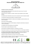
Model 7300A
Infrared Gas Analyzer
7300 S
E R IE S
-R E D
AN
IN F R A
A LY Z E
R
DANGER
HIGHLY TOXIC AND OR FLAMMABLE LIQUIDS OR GASES MAY BE PRESENT IN THIS MONITORING SYSTEM.
PERSONAL PROTECTIVE EQUIPMENT MAY BE REQUIRED WHEN SERVICING THIS SYSTEM.
HAZARDOUS VOLTAGES EXIST ON CERTAIN COMPONENTS INTERNALLY WHICH MAY PERSIST FOR A
TIME EVEN AFTER THE POWER IS TURNED OFF AND DISCONNECTED.
ONLY AUTHORIZED PERSONNEL SHOULD CONDUCT MAINTENANCE AND/OR SERVICING. BEFORE
CONDUCTING ANY MAINTENANCE OR SERVICING CONSULT WITH AUTHORIZED SUPERVISOR/MANAGER.
Teledyne Analytical Instruments
P/N M00000
10/13/00
ECO # 00-0000
i
Model 7300A
Copyright © 2000 Teledyne Analytical Instruments
All Rights Reserved. No part of this manual may be reproduced, transmitted,
transcribed, stored in a retrieval system, or translated into any other language or computer
language in whole or in part, in any form or by any means, whether it be electronic,
mechanical, magnetic, optical, manual, or otherwise, without the prior written consent of
Teledyne Analytical Instruments, 16830 Chestnut Street, City of Industry, CA 917491580.
Warranty
This equipment is sold subject to the mutual agreement that it is warranted by us
free from defects of material and of construction, and that our liability shall be limited to
replacing or repairing at our factory (without charge, except for transportation), or at
customer plant at our option, any material or construction in which defects become
apparent within one year from the date of shipment, except in cases where quotations or
acknowledgements provide for a shorter period. Components manufactured by others bear
the warranty of their manufacturer. This warranty does not cover defects caused by wear,
accident, misuse, neglect or repairs other than those performed by Teledyne or an authorized service center. We assume no liability for direct or indirect damages of any kind and
the purchaser by the acceptance of the equipment will assume all liability for any damage
which may result from its use or misuse.
We reserve the right to employ any suitable material in the manufacture of our
apparatus, and to make any alterations in the dimensions, shape or weight of any parts, in
so far as such alterations do not adversely affect our warranty.
Important Notice
This instrument provides measurement readings to its user, and serves as a tool by
which valuable data can be gathered. The information provided by the instrument may
assist the user in eliminating potential hazards caused by his process; however, it is
essential that all personnel involved in the use of the instrument or its interface, with the
process being measured, be properly trained in the process itself, as well as all instrumentation related to it.
The safety of personnel is ultimately the responsibility of those who control process
conditions. While this instrument may be able to provide early warning of imminent
danger, it has no control over process conditions, and it can be misused. In particular, any
alarm or control systems installed must be tested and understood, both as to how they
operate and as to how they can be defeated. Any safeguards required such as locks, labels,
or redundancy, must be provided by the user or specifically requested of Teledyne at the
time the order is placed.
Therefore, the purchaser must be aware of the hazardous process conditions. The
purchaser is responsible for the training of personnel, for providing hazard warning
methods and instrumentation per the appropriate standards, and for ensuring that hazard
warning devices and instrumentation are maintained and operated properly.
Teledyne Analytical Instruments, the manufacturer of this instrument, cannot
accept responsibility for conditions beyond its knowledge and control. No statement
expressed or implied by this document or any information disseminated by the manufacturer or its agents, is to be construed as a warranty of adequate safety control under the
user’s process conditions.
ii
Teledyne Analytical Instruments
Infrared Gas Analyzer
Technician Record Sheet
The following data is recorded by the technitian at the end of the testing
of the analyzer:
APPLICATION (IMPURITY OF INTEREST):__________________
RANGE 1: FROM____________ TO___________ % / PPM (circle one)
RANGE 2: FROM____________ TO___________ % / PPM (circle one)
RANGE 3: FROM____________ TO___________ % / PPM (circle one)
RANGE 4: FROM____________ TO___________ % / PPM (circle one)
FILTER:
__________________
CALIB_FACTOR:
__________________
HARD_OFFSET_C: __________________
HARD_OFFSET_F: __________________
SOFTWARE VERSION:
SERIAL #:
____________
__________________
Teledyne Analytical Instruments
iii
Model 7300A
iv
Teledyne Analytical Instruments
Table of Contents
OPERATING INSTRUCTIONS
Model 7300A
Infrared Gas Analyzer
Table of Contents
General Purpose
Teledyne Analytical Instruments
i
Model 7300A Infrared Gas Analyzer
Table of Contents
1 Introduction
1.1
1.2
1.3
1.4
1.5
Overview ........................................................................ 1-1
Typical Gas Applications ................................................ 1-1
Main Features of the Analyzer ....................................... 1-2
General .......................................................................... 1-3
NDIR Analyzer ............................................................... 1-3
2 Installation
2.1 Unpacking the Analyzer ................................................. 2-1
2.2 Installing & Connecting the Analyzer ............................. 2-1
2.2.1 IUser Connections ................................................ 2-2
2.2.2 Electrical Power Connections ............................... 2-2
2.2.3 Calibration Gases ................................................. 2-2
2.2.4 Pipe Connection ................................................... 2-3
2.2.5 Sample Delivery System ....................................... 2-3
2.2.6 Venting the System ............................................... 2-3
2.3 Electrical Connections (rear Panel) ............................... 2-3
2.3.1 Primary Input Power .............................................. 2-4
2.3.2 Fuse Installation .................................................... 2-4
2.3.3 50-Pin Equipment Interface Connector ................. 2-4
2.3.3.1 Analog Outputs .............................................. 2-4
2.3.3.2 Alarm Relays ................................................. 2-6
2.3.3.3 Digital Remote Cal Input ................................ 2-7
2.3.3.4 Range ID Relays ........................................... 2-9
2.3.3.5 Network I / O .................................................. 2-9
2.3.3.6 Remote Valve Connector ............................... 2-9
2.3.4 RS-232 Port .......................................................... 2-10
2.4 Gas Requirements ......................................................... 2-12
2.5 Testing the System ......................................................... 2-12
2.6 Calibration ..................................................................... 2-12
2.6.1 Calibration Fluids .................................................. 2-12
2.6.2 Calibration ............................................................. 2-13
ii
Teledyne Analytical Instruments
Table of Contents
3 Start-up and Theory of Operation ......................................... 3-1
3.1 Preliminary ..................................................................... 3-1
3.2 NDIR Analyzer set-up .................................................... 3-1
3.2.1 Initial Set-up and Zeroing ...................................... 3-1
3.2.2 Operational Calibration ......................................... 3.2
3.3 Theory of Operation ....................................................... 3-2
3.3.1 General ................................................................. 3-2
3.4.2 Analyzer ................................................................ 3-3
3.4 Circuit Description ......................................................... 3-5
3.5 Digital Signal Processing & Electronics......................... 3-6
3.6 Linearizer ....................................................................... 3-7
3.7 Control Unit .................................................................... 3-8
3.8 Automatic Function ........................................................ 3-9
4 Operation: Electrical/Control Unit Modes/Functioning
4.1 Introduction .................................................................... 4-1
4.2 Using the Controls ......................................................... 4-2
4.2.1 Mode/Function Selection ...................................... 4-2
4.2.1.1
Analysis Mode ............................................ 4-2
4.2.1.2
Setup Mode ................................................ 4-4
4.2.2 Data Entry ............................................................. 4-5
4.2.2.1
Enter ........................................................... 3-5
4.2.2.2
Escape ....................................................... 3-5
4.3.2 Setting up Auto-Cal................................................ 4-6
4.3.3 Password Protection .............................................. 4-7
4.3.3.1 Entering the Password ................................... 4-7
4.3.3.2 Installing or Changing the Password ............. 4-8
4.3.4 Logging Out ........................................................... 4-9
4.3.5 System Self-Diagnostic Test .................................. 4-9
4.3.6 The Model Screen ................................................. 4-10
4.3.7 Checking Linearity with Algorithm ......................... 4-10
4.3.8 Trouble Shooting Information ................................. 4-11
4.3.9 Digital Flter Setup .................................................. 4-12
4.3.10 Zero Offset Adjustment .......................................... 4-13
4.3.11 CAL-OUT Funtion .................................................. 4-14
4.4 The Zero and Span Functions ....................................... 4-16
4.4.1 Zero Cal ................................................................. 4-16
4.4.1.1 Auto Mode Zeroing ........................................ 4-17
3.4.1.2 Manual Mode Zeroing .................................... 4-18
3.4.1.3 Cell Failure .................................................... 4-18
Teledyne Analytical Instruments
iii
Model 7300A Infrared Gas Analyzer
4.4.2 Span Cal ................................................................ 4-19
4.4.2.1 Auto Mode Spanning ..................................... 4-19
4.4.2.2 Manual Mode Spanning ................................. 4-20
4.5 The Alarms Function ...................................................... 4-21
4.6 The Range Select Function ........................................... 4-23
4.6.1 Manual (Select/Define Range) Screen .................. 4-23
4.6.2 Auto Screen ........................................................... 4-24
4.6.3 Precautions ............................................................ 4-25
4.7 The Analyze Function .................................................... 4-26
4.8 Programming ................................................................. 4-27
4.8.1 The Set Range Screen .......................................... 4-27
4.8.2 The Curve Algorithm Screen ................................. 4-29
4.8.2.1 Checking the Linearization ............................ 4-29
4.8.2.2 Manual Mode Linearization ........................... 4-30
4.8.2.3 Auto Mode Linearization ................................ 4-31
4.9 Special Function Setup .................................................. 4-32
4.9.1 Offset Output / Reverse Output............................... 4-32
4.9.1.1 Output Signal Reversal .................................. 4-32
4.9.1.2 Output Signal Offset ....................................... 4-33
4.9.2 Polarity Reversal .................................................... 4-33
4.9.3 Gain Preset ............................................................ 4-34
5 Maintenance
5.0
5.1
5.2
5.3
5.4
5.5
5.6
6.7
5.8
Fuse Replacement......................................................... 5-1
Routine Maintenance ..................................................... 5-2
Filter ............................................................................... 5-2
NDIR Analyzer Measurement Cell ................................. 5-3
System Self Diagnostic Test ........................................... 5-3
Major Internal Components ............................................ 5-4
Troubleshooting ............................................................. 5-7
General .......................................................................... 5-7
Troubleshooting Chart ................................................... 5-8
A Appendix
Model 7300A Specifications .................................................. A-1
Recommended 2-Year Spare Parts List ................................. A-4
Drawing List ........................................................................... A-4
Exceptions, Gas Cnditions ..................................................... A-6
iv
Teledyne Analytical Instruments
Infrared Gas Analyzer
Introduction 1
1.0 Introduction
1.1
Overview
The Teledyne Analytical Instruments Model 7300A Analyzer, is a
versatile microprocessor-based instrument.
The manual covers the Model 7300A General Purpose 19” Panel/Rack
mounted analyzer. Consisting of an Analysis section and Control Unit
section. The 7300A Analyzer is for indoor or protected use in General
Purpose environments only.
1.2
Typical Gas Applications
Chemical and petrochemical processes
• Combustion and flue gas processes
• Pulp and paper
• Vapor recovery systems
• Enhanced oil recovery
Gas Analysis
CO2 0-2% to 0-100%
CO 0-10% to 0-100%
CH4 0-10% to 0-100%
C2 to C5 0-5% to 0-100%
Food, agriculture, medical
• Metals, ceramics and heat treating atmospheres
Liquid Analysis
Aromatics 0-5%
up to 0-100%
MTBE, ETBE,
TAME 0-20%
Methanol, Ethanol
0-15%
Isobutanes 0-75%
Benzene 0-5%
• Landfill gas power stations
• Emissions testing (part of the mobile stations)
• Carbon dioxide scrubber efficiency
• CO / CO2 / C2H4 monitoring in oxyhydrochlorination
process in EDC manufacturing
Water in solvents 0-5%
(For lower ranges and other liquids or gases, contact factory.)
Other ranges and gases possible with optical cell path/optical filter changes
(consult factory).
Teledyne Analytical Instruments
1-1
1 Introduction
1.3
Model 7300A
Main Features of the Analyzer
The Model 7300A Infrared Gas Analyzer is sophisticated yet simple to
use. The main features of the analyzer include:
•
A easy-to-use front panel interface that includes a red 5-digit
LED display and a vacuum fluorescent display, driven by
microprocessor electronics, that continuously prompts and
informs the operator.
•
High resolution, accurate readings of concentration from low
levels to 100%. Large, bright, meter readout.
•
Versatile analysis over a wide range of applications.
•
Microprocessor based electronics: 8-bit CMOS microprocessor
with 32 kB RAM and 128 kB ROM.
•
Three user definable output ranges (from 0-2% through 0-100 %)
allow best match to users process and equipment.
•
Calibration range for convenient zeroing or spanning.
•
Auto Ranging allows analyzer to automatically select the proper
preset range for a given measurement. Manual override allows
the user to lock onto a specific range of interest.
•
Two adjustable concentration alarms and a system failure alarm.
•
Extensive self-diagnostic testing, at startup and on demand, with
continuous power-supply monitoring.
•
RS-232 serial digital port for use with a computer or other digital
communication device.
•
Analog outputs for concentration and range identification.
(0-1 V dc standard, and isolated 4–20 mA dc)
•
Superior accuracy.
1.4
General
The Model 7300A is a non-dispersive infrared (NDIR) analyzer that
employs the basic principles of spectroscopic analysis to measure a specific
concentration of a gas in a multicomponent gas system. The concentration of
component of interest is determined by exposing a chamber (sample cell)
filled with a gas mixture to infrared radiant energy and measuring how much
of the specific (non-dispersive) infrared wavelength is absorbed by the gas
1-2
Teledyne Analytical Instruments
Infrared Gas Analyzer
Introduction 1
being measured. There is a direct correlation between absorption and the
concentration of the component of interest in the liquid mixture.
1.5
NDIR Analyzer
The Model 7300A contains an optical system consisting of an infrared
(IR) source, sample cell, and detectors. In front of the thermopile detectors
are four interference-type filters. These filters are designated the reference
and measuring filters. The sample flows continuously through the sample
cell, absorbing energy at various wavelengths throughout the IR spectrum.
The wavelengths and intensities of absorption peaks throughout the spectrum
are characteristic of the specific compounds that are present in the sample.
In any photometric analysis, there is always the analysis of the component of interest, and other components (background) which are not of measuring interest. Both the “component of interest” and the background component may have complex IR absorption spectra.
The quantitative measurement of a compound using the 7300A is based
on the Beer-Lambert Law, where the intensity of a beam of monochromatic
radiation transmitted through a sample decreases exponentially as the concentration of the absorbing sample increases. The use of two filters and
detectors allows cancellation of energy changes due to turbidity, dirty sample
cell windows, aging of the source and sudden temperature changes.
The center pass band of the measuring filter is selected to transmit
energy in a narrow region (band pass) where the component of interest
absorbs strongly by comparison with the background components.The center
pass band of the reference filter is generally selected to transmit energy in a
band pass region where the background absorption of IR energy is equivalent to that seen by the measuring filter, and also to be in a region where the
component of interest has minimal absorption of energy. The IR radiation
passes through the sample and filters and strikes the detectors, which convert
the radiation into electrical signals, and are then amplified. Signal processing
involves comparing the measuring and reference signals in order to give a
readout representing the “component of interest” concentration in the sample.
Teledyne Analytical Instruments
1-3
1 Introduction
1-4
Model 7300A
Teledyne Analytical Instruments
Infrared Gas Analyzer
Installation 2
2.0 Installation
Installation of the Model 7300A Infrared Gas Analyzer includes:
1. Unpacking
2. Mounting
3. Gas connections
4. Electrical connections
5. Testing the system.
2.1
Unpacking the Analyzer/Inspection
The analyzer is shipped with all the materials you need to install and
prepare the system for operation. Carefully unpack the analyzer and inspect
it for damage. Immediately report any damage to the shipping agent.
2.2
Installing and Connecting the Analyzer
The 7300A analyzer is a general purpose analyzer and as such is
designed with (non-sealed) enclosures. It must be installed in an area where the
ambient temperature is not permitted to drop below 32°F nor rise above 100°F.
In areas outside these temperatures, auxillary heating/cooling must be supplied.
The 7300A enclosure is oil and dust resistant though designed to resist moisture,
must not be considered completely water-tight. Mounting to walls or racks must
be made securely. Avoid locations that are subject to extreme vibration and
sway.
Sufficient space must be provided around the analyzer to accommodate the
necessary electrical conduit and plumbing connections. The front panel must be
allowed to pull out for possible service access to all components of the enclosure.
Refer to the system/analyzer outline drawings for dimensions.
Regardless of configuration, the analyzer/system must be installed on a
level surface with sufficient space allocated on either side for personnel and test
equipment access. Subject to the foregoing, the Analyzer/System should be
Teledyne Analytical Instruments
2-1
2 Installation
Model 7300A
placed as close to the sample point as possible and bolted to its supporting
surface. When installed as a system with enclosure (non-panel or rack mounted)
a waterproof mastic should be liberally applied to the under surfaces of all
supporting legs of the cubicle system before placing it in position and bolting it
in place.
2.2.1 User Connections
All user connections are on the back of the equipment panel and
appear in the outline diagram in the back of the manual or addendum to the
manual.
2.2.2 Electrical Power Connections
The standard power requires a supply of 100-125VAC, single-phase
power. Power connections are made at the rear panel of the unit. Refer to the
input-output diagram for more information. The electrical power service must
include a high-quality ground wire. A high-quality ground wire is a wire that
has zero potential difference when measured to the power line neutral. If you
have the B option, you will require 220 or 240 VAC, 50/60 Hz power. Check
the analyzer input-output diagram, power schematic, outline, and wiring diagrams for incoming power specifications and connecting points.
Warning: Primary power to the system should not be supplied until
all customer wiring is inspected properly by start-up personnel.
2.2.3 Calibration Gases
The system may require a supply of clean, oil and particulate free air for use
as zero gas.
For accurate calibration, the analyzer requires a blended gas mixture,
typically 80-90% of the full scale range. For examle: a 0-1% CO analyzer should
use a 0.8% to 0.9% CO in N2 bottled mixture. The gas blend should be a
working certified standard, analyzed by the gas supplier to at least 2% accuracy.
Do not restrict the bypass, sample or reference vents of the analyzer (and
sample system when provided). All lines must vent to a stable safe area-typically
1 ATM A +/- 0.005 pressure (0 psig +/- 0.07). Be sure to vent the analyzer exit
to atmospheric unless otherwise indicated by the system piping schematic. Refer
to the systsem outline, piping schematics for proper connections and flow paths
of the analysis system.
2-2
Teledyne Analytical Instruments
Infrared Gas Analyzer
Installation 2
2.2.4 Pipe Connections
Refer to Appendix Piping Drawings for information about pipe connections. On special systems, consult the text in the manual that describes your
particular sample system in detail.
2.2.5 Sample Delivery System
The sample delivery system should be designed to operate reliably and
must be of large enough capacity to avoid flow stops. A pump is required only
if there is insufficient pressure to reliably supply the sample to the system
equipment panel. Do not complicate the delivery system by adding a pump
unless it is absolutely necessary. If a pump is required, select a type that can
handle the sample (corrosion), as well as meet the area classification and
Environmental conditions.
2.2.6 Venting the System
In gas analysis systems, the system vent manifold or bypass/sample vents
must terminate in a safe area as the sample may be poisonous, corrosive or
flammable.
2.3
Electrical Connections (Rear Panel)
Figure 3-3 shows the Model 7300A rear panel. There are connectors
for power, digital communications, and both digital and analog concentration
output.
For safe connections, no uninsulated wiring should be able to come in
contact with fingers, tools or clothing during normal operation.
CAUTION: Use Shielded Cables. Also, use plugs that provide
excellent EMI/RFI protection. The plug case must be
connected to the cable shield, and it must be tightly
fastened to the analyzer with its fastening screws.
Ultimately, it is the installer who ensures that the
connections provide adequate EMI/RFI shielding.
Teledyne Analytical Instruments
2-3
2 Installation
Model 7300A
2.3.1 Primary Input Power
The power cord receptacle and fuse block are located in the same
assembly. Insert the power cord into the power cord receptacle.
DANGER: POWER IS APPLIED TO THE INSTRUMENT'S CIRCUITRY AS LONG AS THE INSTRUMENT IS CONNECTED TO THE POWER SOURCE. THE STANDBY
ON THE FRONT PANEL IS FOR SWITCHING
POWER ON OR OFF TO THE DISPLAYS AND OUTPUTS ONLY.
The standard power supply requires a 110 V ac, 50-60 Hz power source,
or 220 V ac, 50-60 Hz power (optional).
2.3.2 Fuse Installation
The fuse block, at the right of the power cord receptacle, accepts US or
European size fuses. A jumper replaces the fuse in whichever fuse receptacle
is not used.
2.3.3 50-Pin Equipment Interface Connector
Figure 2-1 shows the pin layout of the Equipment Interface connector.
The arrangement is shown as seen when the viewer faces the rear panel of
the analyzer. The pin numbers for each input/output function are given
where each function is described in the paragraphs below.
Figure 2-1: Equipment Interface Connector Pin Arrangement
2.3.3.1
Analog Outputs
There are four DC output signal pins—two pins per output. For polarity, see Table 3-1. The outputs are:
0–1 V dc % of Range: Voltage rises linearly with increasing concentration,
from 0 V at 0 concentration to 1 V at full scale.
(Full scale = 100% of programmable range.)
0–1 V dc Range ID:
2-4
0.25 V = Range 1, 0.5 V = Range 2, 0.75 V =
Range 3, 1 V = Cal Range.
Teledyne Analytical Instruments
Infrared Gas Analyzer
Installation 2
4–20 mA dc % Range: Current rises linearly with concentration, from 4
mA at 0 concentration to 20 mA at full scale. (Full
scale = 100% of programmable range.)
4–20 mA dc Range ID: 8 mA = Range 1, 12 mA = Range 2, 16 mA =
Range 3, 20 mA = Range 4.
Table 2-2: Analog Output Connections
Pin
3
4
5
6
8
23
24
7
Function
+ Range ID, 4-20 mA, floating
– Range ID, 4-20 mA, floating
+ % Range, 4-20 mA, floating
– % Range, 4-20 mA, floating
+ Range ID, 0-1 V dc
– Range ID, 0-1 V dc, negative ground
+ % Range, 0-1 V dc
– % Range, 0-1 V dc, negative ground
Examples:
The analog output signal has a voltage which depends on gas concentration relative to the full scale of the range. To relate the signal output to the
actual concentration, it is necessary to know what range the instrument is
currently on, especially when the analyzer is in the autoranging mode.
The signal output for concentration is linear over the currently selected
analysis range. For example, if the analyzer is set on a range that was defined
as 0–10 % carbon monoxide, then the output would be as shown in
Table 2-3.
Table 2-3: Analog Concentration Output—Example
Percent
Voltage Signal
Current Signal
CO
Output (V dc)
Output (mA dc)
0
1
2
3
4
5
0.0
0.1
0.2
0.3
0.4
0.5
4.0
5.6
7.2
8.8
10.4
12.0
Teledyne Analytical Instruments
2-5
2 Installation
Model 7300A
6
7
8
9
10
0.6
0.7
0.8
0.9
1.0
13.6
15.2
16.8
18.4
20.0
To provide an indication of the range, the Range ID analog outputs are
used. They generate a steady preset voltage (or current when using the
current outputs) to represent a particular range. Table 2-4 gives the range ID
output for each analysis range.
Table 2-4: Analog Range ID Output—Example
Range
Range 1
Voltage (V)
0.25
Range 2
0.50
12
95-100% CO/N2
Range 3
0.75
16
0-100% CO/N2
Range 4 (Cal) 1.00
20
98-100% CO2/N2
2.3.3.2
Current (mA)
8
Application
90-100% CO/N2
Alarm Relays
The nine alarm-circuit connector pins connect to the internal alarm relay
contacts. Each set of three pins provides one set of Form C relay contacts.
Each relay has both normally open and normally closed contact connections.
The contact connections are shown in Table 2-4. They are capable of
switching up to 3 amperes at 250 V ac into a resistive load. The connectors
are:
Threshold Alarm 1:
• Can be configured as high (actuates when concentration is above threshold), or low (actuates when
concentration is below threshold).
• Can be configured as failsafe or nonfailsafe.
• Can be configured as latching or nonlatching.
• Can be configured out (defeated).
Threshold Alarm 2:
• Can be configured as high (actuates when concentration is above threshold), or low (actuates when
concentration is below threshold).
• Can be configured as failsafe or nonfailsafe.
• Can be configured as latching or nonlatching.
• Can be configured out (defeated).
2-6
Teledyne Analytical Instruments
Infrared Gas Analyzer
Installation 2
System Alarm:
Actuates when DC power supplied to circuits is
unacceptable in one or more parameters. Permanently
configured as failsafe and latching. Cannot be defeated. Actuates if self test fails.
(Reset by pressing
button to remove power. Then
press
again and any other button EXCEPT
System to resume.
Further detail can be found in chapter 4, section 4-5.
Table 2-5: Alarm Relay Contact Pins
Pin
45
28
46
42
44
43
36
20
37
Contact
Threshold Alarm 1, normally closed contact
Threshold Alarm 1, moving contact
Threshold Alarm 1, normally open contact
Threshold Alarm 2, normally closed contact
Threshold Alarm 2, moving contact
Threshold Alarm 2, normally open contact
System Alarm, normally closed contact
System Alarm, moving contact
System Alarm, normally open contact
2.3.3.3
Digital Remote Cal Inputs
Accept 0 V (off) or 24 V dc (on) inputs for remote control of calibration. (See Remote Calibration Protocol below.) See Table 2-5 for pin
connections.
Zero:
Floating input. A 5 to 24 V pulse input across the + and –
pins puts the analyzer into the Zero mode. Either side may be
grounded at the source of the signal. A synchronous signal
must open and close the gas control valves appropriately.
Span:
Floating input. A 5 to 24 V pulse input across the + and –
pins puts the analyzer into the Span mode. Either side may
be grounded at the source of the signal. A synchronous signal
must open and close the gas control valves appropriately.
Cal Contact: This relay contact is closed while analyzer is spanning
and/or zeroing. (See Remote Calibration Protocol below.)
Teledyne Analytical Instruments
2-7
2 Installation
Model 7300A
Table 2-6: Remote Calibration Connections
Pin
9
11
10
12
40
41
Function
+ Remote Zero
– Remote Zero
+ Remote Span
– Remote Span
Cal Contact
Cal Contact
Remote Calibration Protocol: To properly time the Digital Remote
Cal Inputs to the Model 7300A Analyzer, the customer's controller must
monitor the Cal Relay Contact.
When the contact is OPEN, the analyzer is analyzing, the Remote Cal
Inputs are being polled, and a zero or span command can be sent.
When the contact is CLOSED, the analyzer is already calibrating. It
will ignore your request to calibrate, and it will not remember that request.
Once a zero or span command is sent, and acknowledged (contact
closes), release it. If the command is continued until after the zero or span is
complete, the calibration will repeat and the Cal Relay Contact (CRC) will
close again.
For example:
1) Test the CRC. When the CRC is open, Send a zero command
until the CRC closes (The CRC will close quickly.)
2) When the CRC closes, remove the zero command.
3) When CRC opens again, send a span command until the CRC
closes. (The CRC will close quickly.)
4) When the CRC closes, remove the span command.
When CRC opens again, zero and span are done, and the sample is
being analyzed.
Note: The Remote Probe connector provides signals to operate the
zero and span gas valves synchronously. However, if you
have the –C Internal valve option, which includes zero and
span gas inputs, the 7300A automatically regulates the zero,
span and sample gas flow.
2-8
Teledyne Analytical Instruments
Infrared Gas Analyzer
Installation 2
2.3.3.4
Range ID Relays
Four dedicated Range ID relay contacts. For any single application they
are assigned to relays in ascending order. For example: if all ranges have the
same application, then the lowest range is assigned to the Range 1 ID relay,
and the highest range is assigned to the Range 3 ID relay. Range 4 is the Cal
Range ID relay. Table 2-7 lists the pin connections.
Table 2-7: Range ID Relay Connections
Pin
21
38
22
39
19
18
34
35
2.3.3.5
Function
Range 1 ID Contact
Range 1 ID Contact
Range 2 ID Contact
Range 2 ID Contact
Range 3 ID Contact
Range 3 ID Contact
Range 4 ID Contact
Range 4 ID Contact
Network I/O
A serial digital input/output for local network protocol. At this printing,
this port is not yet functional. It is to be used in future options to the instrument. Pins 13 (+) and 29 (–).
2.3.3.6
Remote Valve Connector
The 7300A is a single-chassis instrument, which has no Remote Probe
Unit. Instead, the Remote Valve connector is used as another method for
controlling external sample/zero/span gas valves. See Figure 2-5.
Figure 2-5: Remote Probe Connector Pinouts
Teledyne Analytical Instruments
2-9
2 Installation
Model 7300A
The voltage from these outputs is nominally 0 V for the OFF and
15 V dc for the ON conditions. The maximum combined current that can be
pulled from these output lines is 100 mA. (If two lines are ON at the same
time, each must be limited to 50 mA, etc.) If more current and/or a different
voltage is required, use a relay, power amplifier, or other matching circuitry
to provide the actual driving current.
In addition, each individual line has a series FET with a nominal ON
resistance of 5 ohms (9 ohms worst case). This could limit the obtainable
voltage, depending on the load impedance applied. See Figure 2-8.
Figure 3-6: FET Series Resistance
2.3.4
RS-232 Port
The digital signal output is a standard RS-232 serial communications
port used to connect the analyzer to a computer, terminal, or other digital
device. It requires a standard 9-pin D connector.
Output: The data output is status information, in digital form, updated
every two seconds. Status is reported in the following order:
• The concentration in ppm or percent
• The range in use (00 = Range 1, 01 = Range 2, 10 = Range 3, 11
= Range 4)
• The span of the range (0-100 %, etc)
• Which alarms—if any—are disabled (AL–x DISABLED)
• Which alarms—if any—are tripped (AL–x ON).
Each status output is followed by a carriage return and line feed.
Input: The input functions using RS-232 that have been implemented
to date are described in Table 2-8.
2-10
Teledyne Analytical Instruments
Infrared Gas Analyzer
Installation 2
Table 2-8: Commands via RS-232 Input
Command
Description
as<enter>
Immediately starts an autospan.
az<enter>
Immediately starts an autozero.
rp<enter>
Allows reprogramming of two System functions:
APPLICATION (gas use) and ALGORITHM (linearization).
st<enter>
Toggling input. Stops/Starts any status message output from
the RS-232, until st<enter> is sent again.
Implementation: The RS-232 protocol allows some flexibility in its
implementation. Table 2-9 lists certain RS-232 values that are required by
the Model 7300A implementation.
Table 2-9: Required RS-232 Options
Parameter
Baud
Byte
Parity
Stop Bits
Message Interval
2.4
Setting
2400
8 bits
none
1
2 seconds
Gas Requirements
Instrument Air is required for zeroing of the Infrared Analyzer. It must
be free of oil, particulates and water vapor (that will not condensate,
unfiltered plant air is not recommended). A supply pressure of 10-50psig
with a typical flow rate of 0.1 to 0.6 SCFH (50-250 cc/min) is needed.
Bottled gas is recommended (air or Nitrogen) if high quality air is not available.
For accurate calibration, the analyzer requires blended gas mixtures
certified to +/- 2% accuracy.
Teledyne Analytical Instruments
2-11
2 Installation
2.5
Model 7300A
Testing the System
Before plugging the instrument into the power source:
• Check the integrity and accuracy of the fluid connections. Make
sure there are no leaks.
• Check the integrity and accuracy of the electrical connections.
Make sure there are no exposed conductors
• Check that sample pressure is controlled accuracately and is
maintained between 5 to 10 psig, according to the requirements
of your process.
NOTE: Special designed systems may require checks under vacuum
or high pressure (consult manual addendum).
Power up the system, and test it by performing the following
operations:
1. Repeat the Self-Diagnostic Test, section 5.2
2.6
Calibration
2.6.1 Calibration Fluids
Zero fluids must be made by the chemistry lab or certified zero and span
gas bought from a gas supplier. The zero fluid must be the major component of
the sample, free from the component of interest.
Note: In Non-purity applications, the reference cell may be sealed
with clean air (consult factory).
The span fluid must be the major component of the sample mixed with
a small amount of the component of interest. The concentration must be 80 to
95% of the full scale range or the widest range of the instrument (if the instrument
provides more than one range).
2.6.2 Calibration
Refer to Section 4.4 of the manual to determine how to manipulate the
mode setting. The recommended calibration method is as follows:
Method:
2-12
Teledyne Analytical Instruments
Infrared Gas Analyzer
Installation 2
1. Introduce zero fluid and set zero as referred in section 4.4.1
NOTE: When calibrating from 0% to an upper concentration gas, obtain
a zero gas (minus the analyte) that typically is as pure as the minimum resolution
needed to control to. This usually meets or exceeds the minimum full scale
accuracy of the measurement.
2. Introduce a span fluid and set the concentration of the span fluid.
Refer to the span procedure in section 4.4.2. (Note: The span gas should
typically be an 80% of full scale range gas similar to the 100% zero gas
background; i.e., 100% CO zero gas and a span gas of 98.4% CO2 in N2 for
2
a 98-100%CO2 purity application.
Teledyne Analytical Instruments
2-13
2 Installation
2-14
Model 7300A
Teledyne Analytical Instruments
Infrared Gas Analyzer
Start-up and Operation
3.0 Start-up and Operation
3.1 Preliminary
Before applying power to the system, TAI suggests that the electrical
wiring installation be checked against the system input-output diagram.
Proper attention to this preliminary check will prevent severe damage caused
by wiring errors.
Also, verify that all connections to the system have been made
correctly. Refer to the system outline diagram for proper connections.
3.2 NDIR Analyzer Startup
Before power is supplied to the analyzer, TAI recommends the following operator’s check be performed:
1. Check for loose or damaged components.
2. Verify that all plug-in circuit cards are firmly seated in their
receptacles.
3. Inspect and verify that all wiring connections are in agreement
with the system Interconnection diagram.
4. Check for correct span gases. (See 4.2: Preparation for Calibration).
5. Check that sample pressure is regulated to ± .5% of nominal
operating pressure.
6. Check and assure sample remains above dewpoint to eliminate
any condensation from sample tap to return point.
Power up the unit by depressing the rear panel switch. From a first
time power-on warm start attempt, allow (1) one hour warm-up to proceed.
Observe that the Digital display will go through a diagnostic routine before
the readings revert to a continuous concentration readout.
3.2.1 Initial Set-up and Zeroing
Assure the sample will enter from the zero inlet gas position. Open the
zero gas tank and set the pressure regulator to 20 psig. Set the zero gas flow
Teledyne Analytical Instruments
3-1
3 Start-up and Theory of Operation
Model 7300A
and sample flow between 0.1 to 0.6 SCFH (50-250 cc/min) .
Zero standard gas must have a composition similar to sample, an ideally,
contains none of the components of interest.
Initialize a zero operation through the system menu. Refer to Section 4
for Electronics /Control Unit Modes and Functioning to navigate the zero
menu.
After the zero cycle is over, the instrument is not yet calibrated. Permit
the instrument to operate in this mode for at least 3 hours to stabilize if not
already done so upon initial power up. Repeat Zero Calibration followed by
a Span Calibration.
NOTE: The following options could be included in your system:
In case the instrument is part of a multi instrument system, where all
instruments are connected to the same sample system and under control of a
single timer, all instruments of the system will go through the zero and
sample cycle simultaneously. The Control Unit of the instrument which
houses the timer and operates the sampling system is called the master. The
other Control Units of the other instruments are called slaves.
Each of the other instruments may be monitoring the concentration of
several different gases of interest in the sample, for example CO, CO2 and/or
Combustibles as CH4 in flue gas.
3.2.2 Operational Calibration
After the instrument has stabilized, let zero gas flow through the
analyzer
Perform a zero of the analyzer.
After the Zero operation, and analyzer returnining to sample, perform a
Span calibration.
Open the span gas tank and set the pressure regulator to 20 psig.
Switch the mode switch to sample. Refer to Section 4 again.
Induce an automatic zero cycle as described in Section 4 also.
After the zero cycle, the analyzer reverts to the sample cycle. The
sample reading is now accurate and the analyzer is placed in continuous
operation. See Sections 4.6-4.8.
NOTE: In case slave analyzers are involved, calibrate them
simultaneously with the master analyzer.
After the instrument is calibrated, when no Auto-Cal option was
selected, shut off the main valve on the span and zero gas tanks. These tanks
3-2
Teledyne Analytical Instruments
Infrared Gas Analyzer
Start-up and Operation
are not used during automatic sampling.
3.3
Theory of operation
3.3.1 General
The non-dispersive infrared (NDIR) analyzer is one of the major components
of the system. It employs the basic principles of spectroscopic analysis to
measure a specific concentration of one gas in a multicomponent gas system.
The concentration of a gas is determined by exposing a chamber filled with a
gas mixture to infrared radiant energy and measuring how much of the
specific (non-dispersive) infrared wavelength is absorbed by the gas being
measured.
As an example, the NDIR analyzer is used most in flue gas applications
where the amount of carbon monoxide in a flue gas mixture is measured.
The specific infrared wavelength at which the carbon monoxide molecule
absorbs infrared energy is at 4.65 microns. The more carbon monoxide
present in the measurement cell, the more energy its molecules absorb.
The NDIR analyzer needs four basic components to measure the spectral
absorbance.
a) A source of emitted infrared radiation to be absorbed by the gas of
interest.
b) A chamber opened to accept a flowing sample gas.
c) A detector specifically tuned to measure only the wavelength of infrared
energy that will be absorbed by the gas being measured. For example,
carbon monoxide requires a detector turned to 4.65 microns, while carbon
dioxide needs one tuned to 4.27 microns.
d) An electronics system to process the changes in the electronic resistance
of the detector, and to convert these changes into specific electronics signals
that deliver a voltage at current linearly proportional to the concentration of
the gas measured. The Teledyne NDIR analyzer employs all of the above
features.
3.3.2 Analyzer
The emitted IR energy is generated by one specially configured miniature
lamps in parabola’s focused and operating at low power of only 0.5 watts.
Teledyne Analytical Instruments
3-3
3 Start-up and Theory of Operation
Model 7300A
These lamps are typically rated for 20,000 hours continuous operation when
run in the DC mode (+5VDC). This collimated energy is directed through
parallel infrared beams. The radiant energy passes through tubes containing a
continuously flowing sample gas. As the beam passes through the reference
tube, the energy of the beam is unattenuated and balanced which provides a
standard of source energy output for comparison. The gas of interest is
present in the measurement tube, however, the energy of the beam will be
attenuated at the specific absorption wavelength.
After passing through the two tubes, the radiant beams are reflected and
imaged by a second concave mirror onto a photon detector. A spectral filter,
located just in front of the detector, represents the precise “window” of the
absorption band for the specific gas of interest. Energy outside the band is
eliminated.
The detector converts the optical energy from the radiant beams into an
electrical signal which is modulated in proportion to the gas concentration.
D etecto r
P ream p
D iffere nce
A m plifier
IR
S ource
D etecto r
Auto Z ero
A m plifier
A to D
C onve rter
P ream p
To C P U
M
U
X
Th erm istor
H eater
AutoR ang e
Temperature
Control
Fine
Adjustment
C oarse
A djustm ent
D ig itial to
A nalo g
C onve rter
(DAC )
0-1 V dc
C oncen tration
and R an ge
4-20 m A dc
C oncen tration
and R an ge
A larm 1
A larm 2
S ystem
Fa ilure
A larm
R S -232
C e n tra l
P ro ce ssin g
U n it
(C P U )
D isplays
P rocessing
R ang e
C ontacts (4)
E xtern al
Valve
C ontrol
R em ote Sp an
C ontrol
Pow er
S upply
A to D C onv
R em ote Zero
C ontrol
C al
C ontact
Block Diagram of the Model 7300A Electronics
3-4
Teledyne Analytical Instruments
Infrared Gas Analyzer
Start-up and Operation
3.4 Circuit Description
The Teledyne Analytical Instruments IR bench is a multiple wavelength, single beam design. It uses a quadruple detector that consists of a
specially designed, patented thermopile with small IR filters mounted in front
of it to produce independent voltages. These correspond to the transmission
of energy at each filter’s wavelength. They are amplified by special high
stability operational amplifiers to produce the output of the device.
IR energy is generated by a filament (IR source) operating at a moderately elevated temperature.
The cell cavity allows the sample gases to pass between the IR source
and the detector. Sapphire cell windows allow passage of this IR energy
with minimal absorption. The gases that pass through the cell absorb energy
of the IR band at different wavelengths within the spectrum.
An optical filter is mounted on the face of each detector. Each detector
responds to a particular wavelength, producing a voltage proportional to the
energy that has passed through the gas and filter. If the gas concentration
changes, the energy at the measuring wavelength changes, changing only the
measuring voltage output. The reference voltage output is not affected by the
gas concentration changes. This “measurement” voltage change is electronically processed as the instrument’s output signal
IR Bench Block Diagram
Teledyne Analytical Instruments
3-5
3 Start-up and Theory of Operation
3.5
Model 7300A
Digital Signal Processing & Electronics
The Model 7300A uses an 8031 microcontroller (Central Processing
Unit—CPU) with 32 kB of RAM and 128 kB of ROM to control all signal
processing, input/output, and display functions for the analyzer. System
power is supplied from a universal power supply module designed (C65507)
to be compatible with any international power source. (See Major Internal
Components in chapter Maintenance for the location of the power supply
and the main electronic PC boards.)
The Temperature Control board (C69535A) is set to a single voltage
(110 or 220 VAC) and set the temperature of the sampling system at 45oC.
The signal processing electronics including the microprocessor, analog to
digital, and digital to analog converters are located on the Motherboard
(C67435B) on side of the case.
The detector output level depends on the intensity of the IR source, the
length of the cell and the type of fluid in the cell. Usually the output is
between 0.2 and 0.9 mVDC. The Teledyne detector consists of four detectors: A, B, C and D. They are strapped to the inputs of the positive, very
high-gain amplifiers U1, U2, U3, and U4. Amplifiers U1 through U4 are
high quality, very low offset amplifiers.
Preamplified signals (usually between .2 to 1.0 volt) are delivered via
the ribbon cable to the measuring board through an 8-point dip switch.
Connectors deliver power from the measuring board to the amplifiers and
300–450 mADC current to the IR source.
The motherboard serves as a power distribution and interface board.
The Auto-Zero amplifier PCB board is mounted on top of the
Motherboard. These boards are accessible by sliding the system out of the
case after removing the screws on the back plate.
The Temperature Control Board keeps the temperature of the measuring cell regulated to within 0.1 degree C. A thermistor is used to measure the
temperature, and a zero-crossing switch regulates the power of the heaters
inside the sample chamber. The result is a sensor output signal that is temperature independent.
The output of the preamp is fed to variable gain amplifier, which
provides automatic range switching under control of the CPU. The output
from the variable gain amplifier is sent to an 18 bit analog to digital converter.
The digital concentration signal along with input from the control panel
is processed by the CPU and passed on to the 12-bit DAC, which outputs 01 V dc Concentration and Range ID signals. An voltage-to-current converter
provides 4-20 mA dc concentration signal and range ID outputs.
3-6
Teledyne Analytical Instruments
Infrared Gas Analyzer
Start-up and Operation
The CPU also provides appropriate control signals to the Displays,
Alarms, and External Valve Controls, and accepts digital inputs for external
Remote Zero and Remote Span commands. It monitors the power supply
through an analog to digital converter as part of the data for the system
failure alarm it performs timing and linearizing tasks too.
The RS-232 port provides two-way serial digital communications to
and from the CPU. These, and all of the above electrical interface signals are
described in detail in chapter 3 Installation.
3.6
Linearizer
NDIR Bench Output
The output of the NDIR analyzer bench is non-linear (this is due to the effect
known as “Beers Law”). Figure I shows this non-linear response.
Figure I
Gas Concentration
In order to produce a linear signal response, a compensation curve is
required (see Figure II). Therefore, a linearizer software routine is included
to create a linear response. Refer to section 4.3.7 and 4.8.2 to see how
linearizer is programmed.
Teledyne Analytical Instruments
3-7
3 Start-up and Theory of Operation
Model 7300A
Figure I
Linearizer Output
Gas Concentration
NDIR Bench Output
Figure II
Linearizer Input
Piece-wise approximation is the method used to linearize the signal, i.e., the
linearizer’s output to input relationship can be graphed as a number of
straight line segments connected together to approximate the desired curve
that would be required to compensate for the nonlinearity of the bench
The points at which the compensation curve changes slope are called
breakpoints. The slope of each segment corresponds to the gain of the
linearizer in that segment, and this gain has to vary according to the input
voltage. This is achieved through software by adjusting a multiplier factor at
each straight line segment. The linearizer has nine specific voltage segments.
3-8
Teledyne Analytical Instruments
Infrared Gas Analyzer
3.7
Start-up and Operation
AUTOMATIC FUNCTION (Optional)
The events talking place during a zero cycle are as follows:
l. The zero cycle starts with activation of the calibration contact. The
analyzer outputs are held during the zero cycle.
2. The Auto Zero solenoid valve (optional) is activated and zero gas replaces
the sample. (This valve may be internal or external to the Model 7300A
enclosure).
3. At about minute one in the cycle. The Auto Zero board then begins its
zeroing function, adjusting the processing circuitry of the analyzer to develop
a zero signal output. During this period, the analyzer display may swing
from below zero to above fullscale several times before it finally settles to
zero output. The “hold” feature prevents these wide output excursions from
affecting the analog output and trigger alarms. The Auto Zero circuit board
function takes about 6 minutes to complete. It is important that zero gas is
continually purging the cell during this time.
4. At around the 5th minute, the Auto Zero solenoid valve is deactivated and
sample replaces the zero gas.
5. The hold feature is deactivated and the display starts reading the sample
again, and the analog output soon starts tracking.
This concludes the zero cycle.
The time between zero cycles, may be programmed to last from one (1) to 23
hours.
For “Purity Measurements” typical zeroing is performed every 3 hours. This
may increase or decrease depending upon the complexity of the application
involved.
Teledyne Analytical Instruments
3-9
3 Start-up and Theory of Operation
3-10
Teledyne Analytical Instruments
Model 7300A
Infrared Gas Analyzer
Operation 4
Operation
4.1
Introduction
Although the Model 7300A is usually programmed to your application
at the factory, it can be further configured at the operator level, or even,
cautiously, reprogrammed. Depending on the specifics of the application,
this might include all or a subset of the following procedures:
• Setting system parameters:
• Establish a security password, if desired, requiring Operator
to log in.
• Establish and start an automatic calibration cycle, if desired.
• Routine Operation:
• Calibrate the instrument.
• Choose autoranging or select a fixed range of analysis.
• Set alarm setpoints, and modes of alarm operation (latching,
fail-safe, etc).
• Program/Reprogram the analyzer:
• Define new applications.
• Linearize your ranges.
• Special functions setup:
• Set output reversal.
• Set polarity reversal or offset output.S
• Set gain amplification.
Before you configure your 7300A, the following default values are in
effect: RANGE/APPLICATIONS: refer to data sheet on the first page of
this manual;
Range:
Manual
Alarm Relays:
Defeated, 0.00%, HI, NOT Fail/Safe, not latching
Zero:
Auto, every 0 days 0 hours
Span:
Auto, at 10%, every 0 days, at 0 hours
Password: TAI
Teledyne Analytical Instruments
4-1
4 Operation
4.2
Model 7300A
Using the Controls
To get the proper response from these controls, press the desired key
(ESCAPE or ENTER—DOWN or UP). To enter the screen menu, press any
key.
The item that is between arrows on the screen is the item that is currently
selectable by pressing the ENTER enter key.
In these instructions, to ENTER means to press the ENTER KEY, and to
ESCAPE means to press the ESCAPE KEY. To scroll UP (or scroll DOWN)
means to press UP or DOWN keys as many times as necessary to reach the
required menu item.
4.2.1 Mode/Function Selection
When the analyzer is first powered up, and has completed its initialization
and self diagnostics, ESCAPE toggles the instrument between the ANALYZE
screen (Analysis Mode) and the MAIN MENU screen (Setup Mode). The
ANALYZE screen is the only screen of the Analysis Mode.
The MAIN MENU screen is the top level in a series of screens used in the
Setup Mode to configure the analyzer for the specific application. The DOWN/
UP commands scroll through the options displayed on the VFD screen. The
selectable option appears between arrows. When you reach the desired option
by scrolling, ENTER the selection as described below.
ESCAPE takes you back up the hierarchy of screens until you reach the
ANALYZE MODE. ESCAPING any further just toggles between the MAIN
MENU and the ANALYZE screen.
NOTE:
The main menu times out after 5 (five) seconds, returning
to the analyze screen. Submenus time out after 10 minutes.
4.2.1.1 Analysis Mode
This is the normal operating mode. The analyzer monitors the oconcentration of the mixure content of the sample, displays the percent of the concentration in the sample stream, and warns of any alarm conditions. Pressing any key
switches you to Setup Mode. Setup Mode switches back to Analyze Mode if
no controls are used for more than five seconds.
4-2
Teledyne Analytical Instruments
Infrared Gas Analyzer
Operation 4
SETUP MODE
Span/Zero
Off/On
Span/Zero
Timing
PSWD
Enter
Password
Change
Yes/No
LOGOUT
Secure Sys &
Analyze Only
MODEL
Show Model
and Version
SELF-TEST
Self-Test in
Progress
AUTO-CAL
Auto/Manual
Span Select
Span Value
Set
ZERO
Auto/Manual
Zero Select
Zero in
Progress
ALARMS
Select
Range
Gas Use
Range
RANGE
Yes
Change
Password
Verify
Password
Slef-Test
Results
SPAN
Man
Span/Zero
Off/On
Select
Range
Span in
Progress
% / ppm
Select
Setpoints &
Attributes
Define
Range
Auto/Manual
Range Adj
Gas
Auto Application
HARDW-VAR
Troublshooting Data
FILTER
Set Digital
Filter
CALOUTPUT
APPLICATION
Calibrate Analog
Output
Select
Range
Define
Appl/Range
Select
OFF/INV
Ver
ALOGORITHM
Select
Range
OFFSET
Set Zero
Offset
CAL-INDPD
STAND-BY
Gas Use
Range
Select
Verify/Setup
Verify
Points
Enter
Man Input/Output
Values
Enter
Auto/Manual
Set Linearity Cal
Select Linrty
Auto Span Values
Enter
Calibrate one
range at a time
ON w/out
displays/outputs
Figure 4-1: Hierarchy of Functions and Subfunctions
Teledyne Analytical Instruments
4-3
4 Operation
Model 7300A
4.2.1.2 Setup Mode
The MAIN MENU consists of 14 functions you can use to customize and
check the operation of the analyzer. Figure 4-1 shows the functions available
with the 7300A. They are listed here with brief descriptions:
1 AUTO-CAL: Used to define and/or start an automatic calibration
sequence.
2 PSWD: Used to establish password protection or change the
existing password.
3 LOGOUT: Logging out prevents unauthorized tampering with
the analyzer settings.
4 MODEL: Displays Manufacturer, Model, and Software version
of the instrument.
5 SELF-TEST: The instrument performs a self-diagnostic routine
to check the integrity of the power supply, output boards, cell and
amplifiers.
6 SPAN: Set up and/or start a span calibration.
7 ZERO: start a zero calibration.
8 ALARMS: Used to set the alarm setpoints and determine
whether each alarm will be active or defeated, HI or LO acting,
latching or not, and failsafe or not.
9 RANGE: Used to set up three analysis ranges that can be
switched automatically with auto-ranging or used as individual
fixed ranges.
10 HARDW-VAR: This function displays parameters used by the
software for some calculations. It is a troubleshooting tool to be
used by qualified technicians.
11 FILTER: This function sets the digital filter from 0 to 10, 0
being faster response time, and 10 being the slowest. The default
is 4.
12 CAL_OUTPUT: Calibrate Analog Output
13 APPLICATIONS: Restricted function, not generally accessed
by the end user. Used to define up to three analysis ranges and a
calibration range (including impurity, background low end of
range, high end of range, and % of ppm units).
14 ALOGORITHM: Arestricted function, not generally accessed
by the end user. Used to linearize the output for the range of
interest.
4-4
Teledyne Analytical Instruments
Infrared Gas Analyzer
Operation 4
15 OFFSET: This function helps set a non-zero offset to the zero
calibration. It is useful when zeroing the analyzer with a
background gas that is different than the sample.
16 CAL-INDEPD: Not generally accessed buy the end user.
Forces analyzer to be in independent calibration mode.
17 STANDBY: Remove power to outputs and displays, but
maintain power to internal circuitry.
Any function can be selected at any time. Just scroll through the MAIN
MENU with the DOWN/UP keys to the appropriate function, and ENTER it.
The analyzer will immediately start that function, unless password restrictions
have been assigned. (Password assignment is explained further on.)
All of these functions are described in greater detail in the procedures
starting in section 4.3. The VFD screen texts used to illustrate the procedures
are reproduced in a Monospaced type style.
4.2.2 Data Entry
4.2.2.1 ENTER
When the selected option is a function on the Main Menu screen, the
function name appears between the arrows on the screen. You activate the
function by the ENTER key.
When the selected option is a function or subfunction, ENTER moves
the display to the VFD screen for that function or subfunction.
When the selected option is a modifiable item, theUP or DOWN keys
can be used to increment or decrement that modifiable item to the value or action
you want. Then you ENTER the item, which also puts you into the next field to
continue programming.
When the last field is entered, ENTER takes you to the next screen in the
process, or if the process is completed, ENTER takes you back to the ANALYZE screen.
4.2.2.2 ESCAPE
Pressing the ESCAPE key takes you back to the previous screen.
Teledyne Analytical Instruments
4-5
4 Operation
Model 7300A
If you do not wish to continue a function, you can abort the session by
escaping . Escaping a function takes the analyzer back to the previous screen, or
to the ANALYZE Function, depending on the function escaped.
reproduced, at the appropriate point in the procedure, in a Monospaced type style. Push-button names are printed in Oblique type.
4.3.2 Setting up an AUTO-CAL
When proper automatic valving is connected (see chapter 3, installation),
the Analyzer can cycle itself through a sequence of steps that automatically zero
and span the instrument.
Note: Before setting up an AUTO-CAL, be sure you understand the
Zero and Span functions as described in section 4.4, and
follow the precautions given there.
Note: If you require highly accurate AUTO-CAL timing, use external
AUTO-CAL control where possible. The internal clock in the
Model 7300A is accurate to 2-3 %. Accordingly, internally
scheduled calibrations can vary 2-3 % per day.
Note: If your ranges are configured for different applications, then
AUTO-CAL will calibrate all of the ranges simultaneously (by
calibrating the Cal Range).
To setup an AUTO-CAL cycle:
The VFD will display five subfunctions.
Call out MAIN MENU, scroll to AUTO-CAL function, and ENTER. A
new screen for ZERO/SPAN set appears.
ZERO in
SPAN in
Ød
Ød
Øh off
Øh off
Use UP or DOWN key to blink ZERO (or SPAN), then Enter. (You
won’t be able to set OFF to ON if a zero interval is entered.) A Span Every ...
(or Zero Every ...) screen appears.
Zero schedule: OFF
Day:
Ød Hour:
Øh
Use UP or DOWN key to set a value in days, then ENTER to move to the
start-time value in hours. Use UP or DOWN keys to set a start-time value, then
ENTER.
To turn ON the SPAN and/or ZERO cycles (to activate AUTOCAL): useUP
or DOWN keys to set the OFF/ON field to ON. You can now turn these fields
ON because there is a nonzero span time defined.
4-6
Teledyne Analytical Instruments
Infrared Gas Analyzer
Operation 4
4.3.3 Password Protection
Before a unique password is assigned, the system assigns TAI by default.
This password will be displayed automatically. The operator just presses the
Enter key to be allowed total access to the instrument’s features.
If a password is assigned, then setting the following system parameters can
be done only after the password is entered: alarm setpoints, AUTO-CAL
setup. ZERO/SPAN calibration assigning a new password, range/application
selections, and curve algorithm linearization. (APPLICATION and ALGORITHM are covered in the programming section.) However, the instrument can
still be used for analysis or for initiating a self-test without entering the password.
To defeat security the password must be changed back to TAI.
NOTE: If you use password security, it is advisable to keep a copy of
the password in a separate, safe location.
4.3.3.1
Entering the Password
To install a new password or change a previously installed password, you
must key in and ENTER the old password first. If the default password is in
effect, pressing the ENTER button will enter the default TAI password for you.
Call out MAIN MENU setup by selecting any controls
Use the UP or DOWN key to scroll the blinking over to PSWD, and press
Enter to select the password function. Either the default TAI password or AAA
place holders for an existing password will appear on screen depending on
whether or not a password has been previously installed.
Enter password:
T A I
or
Enter password:
A A A
The screen prompts you to enter the current password. If you are not using
password protection, press Enter to accept TAI as the default password. If a
password has been previously installed, enter the password using the ENTER
key to scroll through the letters, and the UP or DOWN key to change the
letters to the proper password. The last ENTER enters the password.
In a few seconds, you will be given the opportunity to change this password or keep it and go on.
Change Password?
<ENT>=Yes
<ESC>=No
Teledyne Analytical Instruments
4-7
4 Operation
Model 7300A
Press Escape to move on, or proceed as in Changing the Password,
below.
4.3.3.2
Installing or Changing the Password
If you want to install a password, or change an existing password, proceed
as above in Entering the Password. When you are given the opportunity to
change the password:
Change Password?
<ENT>=Yes
<ESC>=No
Enter to change the password (either the default TAI or the previously
assigned password), or press Escape to keep the existing password and move
on.
If you chose Enter to change the password, the password assignment
screen appears.
Select new password
T A I
or
Select new password
AAA
Enter the password using theUP or DOWN keys and ENTER to scroll
through the existing password letters, and the UP or DOWN keys to change the
letters to the new password. The full set of 94 characters available for password
use are shown in the table below.
Characters Available for Password Definition:
A
K
U
_
i
s
}
)
3
=
4-8
B
L
V
`
j
t
→
*
4
>
C
M
W
a
k
u
!
+
5
?
D
N
X
b
l
v
"
'
6
@
E
O
Y
c
m
w
#
7
F
P
Z
d
n
x
$
.
8
G
Q
[
e
o
y
%
/
9
H
R
¥
f
p
z
&
0
:
Teledyne Analytical Instruments
I
S
]
g
q
{
'
1
;
J
T
^
h
r
|
(
2
<
Infrared Gas Analyzer
Operation 4
When you have finished typing the new password, press Enter. A verification screen appears. The screen will prompt you to retype your password for
verification.
Enter PWD To Verify:
A A A
Use the UP/DOWN key to retype your password and use ENTER to
scroll through the letters, and last enter will complete verification. Your password
will be stored in the microprocessor and the system will immediately switch to
the Analyze screen, and you now have access to all instrument functions.
If all alarms are defeated, the Analyze screen appears as:
1.95
nR1:
% CO2
Ø 1Ø Anlz
If an alarm is tripped, the second line will change to show which alarm it is:
1.95
AL1
% CO2
NOTE:If you log off the system using the LOGOUT function in the
MAIN MENU, you will now be required to reenter the password
to gain access to Alarm, and Range functions.
4.3.4 Logging Out
The LOGOUT function provides a convenient means of leaving the analyzer
in a password protected mode without having to shut the instrument off. By
entering LOGOUT, you effectively log off the instrument leaving the system
protected against use until the password is reentered. To log out, scroll to field of
LOGOUT function, and ENTER to logout The screen will display the message:
Protected until
password entered
4.3.5 System Self-Diagnostic Test
The Model 7300A has a built-in self-diagnostic testing routine. Preprogramming signals are sent through the power supply, output board, preamp
board and sensor circuit. The return signal is analyzed, and at the end of the test
the status of each function is displayed on the screen, either as OK or as a
number between 1 and 1024. (See System Self Diagnostic Test in chapter 5
for number code.) If any of the functions fails, the System Alarm is tripped.
Note: The sensor will always show failed unless identical gas is
present in both channels at the time of the SELF-TEST.
Teledyne Analytical Instruments
4-9
4 Operation
Model 7300A
The self diagnostics are run automatically by the analyzer whenever the
instrument is turned on, but the test can also be run by the operator at will. To
initiate a self diagnostic test during operation, use the UP/DOWN key to scroll
through the MAIN MENU to the SELFTEST and Enter. The screen will follow
the running of the diagnostic.
RUNNING DIAGNOSTIC
Testing Preamp Cell
When the testing is complete, the results are displayed.
Power: OK Analog: OK
Cell:
2 Preamp: 3
The module is functioning properly if it is followed by OK. A number
indicates a problem in a specific area of the instrument. Refer to Chapter 5
Maintenance and Troubleshooting for number-code information. The results
screen alternates for a time with:
Press Any Key
To Continue...
Then the analyzer returns to the initial System screen.
4.3.6 The Model Screen
Scroll through the MAIN MENU to MODEL and Enter. The screen
displays the manufacturer, model, and software version information.
4.3.7 Checking Linearity with ALGORITHM
Use UP/DOWN control to select ALGORITHM, and Enter.
sel rng to set algo:
> Ø1 Ø2 Ø3
<
Use the UP/DOWN Control to select the range: 01, 02, or 03. Then press
Enter.
Gas Use:
CO2
Range:
Ø 10%
Enter again.
Algorithm setup:
VERIFY
SET UP
Use UP/DOWN key to select and Enter VERIFY to check whether the
linearization has been accomplished satisfactorily.
4-10
Teledyne Analytical Instruments
Infrared Gas Analyzer
Operation 4
Dpt
Ø
INPUT
Ø.ØØ
OUTPUT
Ø.ØØ
The leftmost digit (under Dpt) is the number of the data point being monitored. Use the UP/DOWN key to select the successive points.
The INPUT value is the input to the linearizer. It is the simulated output of
the analyzer. You do not need to actually flow gas.
The OUTPUT value is the output of the linearizer. It should be the ACTUAL concentration of the span gas being simulated.
If the OUTPUT value shown is not correct, the linearization must be corrected. ESCAPE to return to the previous screen. Select and Enter SET UP to
Calibration Mode screen.
Select algorithm
mode : AUTO
There are two ways to linearize: AUTO and MANUAL: The auto mode
requires as many calibration gases as there will be correction points along the
curve. The user decides on the number of points, based on the precision required.
The manual mode only requires entering the values for each correction
point into the microprocessor via the front panel buttons. Again, the number of
points required is determined by the user.
4.3.8 Troubleshooting information
Accessing the HARDW_VAR function will allow a qualified technician
to get further information on the health of the analyzer. This is a complimentary
troubleshooting tool to SELF-TEST. Information displayed in the VFD display is
shown below:
Calib_factor = 5.00
AtoD_ave = 1289
lOffset[r][g] = 492
(This is the slope calibration value of the span,
default is 5.00)
(This is the raw ADC count, -262144 to
262143 are acceptable raw counts but must still
be evaluated by knowing what gas is flowing
through the analyzer)
(This is the current zero offset from the zero
calibration of the gain and range the instrument is
on at the moment. It should be between
10,000 to 10,000)
Teledyne Analytical Instruments
4-11
4 Operation
Model 7300A
Hard_offset_C=3015 (This is the raw DAC count of the Coarse zero
adjustment. It should read between 0 and 4095)
Hard_offset_F=2715 (This is the raw DAC count of the Fine zero
adjustment. It should read between 0 and 4095)
Current_gain = 4
(This is the gain the analyzer is on, it should read
between 0 and 9)
4.3.9
Digital Filter Setup
The 7300A analyzer has the option of decreasing or increasing the
amount of filtering on the signal. This feature enhances the basic filtering done by
the analog circuits by setting the amount of digital filtering effected by the microprocessor. To access the digital filter setup, scroll through the menu and select
FILTER. Press the Enter key to see the following screen:
Enter Digital
Filter:
4
The number on the second row can be adjusted from 0, minimum digital
filtering, to 10, maximum digital filtering. The default setting is 4 and that should
suffice for most applications. In some applications where speeding the response
time with some trade off in noise is of value, the operator could decrease the
number of the digital filter. In applications where the signal is noisy, the operator
could switch to a higher number; the response time is slowed down though.
10 to 90% response time on the different settings to a step input is
shown below. This response time does not include the contributions of the bench
sampling system and the preamplifier near the detector.
Setting
0
1
2
3
4
5
4-12
10-90% Response
(seconds)
2.5
5
10
20
40
80
Teledyne Analytical Instruments
Infrared Gas Analyzer
6
7
8
9
10
Operation 4
160
320
640
1280
2360
The response time listed above can and will change depending on the
application and they merely serve to illustrate the effect of the digital filter. The
digital filter disengages if there is an upset that is more than 5% of full scale. As
the reading comes within the range, the filter becomes active once again.
4.3.10
Zero Offset Adjustment
The software in this instrument provides a way to enter an offset on the
zero operation of the analyzer. If the background gas of the process is different
than the zero calibration gas being used, the reading will have an offset that will
be constant throughout its working range. Thus, the need to provide an offset
when the instrument is being zeroed.
How to access the offset function:
To access this function, Scroll through the menu and select OFFSET.
Press the Enter key to see the following screen:
Enter zero offset:
0.00 %
The offset value can be modified by using the Up/Down keys. Next section
shows how to select this value. Suffice to say that whatever value you enter, will
be automatically added to the reading. Thus, if you entered -0.10 %, at the end
of the zero the display will show -0.10 %.
When the instrument enters the zero mode in AUTO, the instrument will do
the work of bringing the reading back to zero plus the offset value that was
entered. If you chose MANual zero mode, then you must adjust the zero of the
instrument the corresponding section of the manual but with one difference:
instead of bringing the display to read zero, you must make the display read zero
plus the value entered as offset.
Teledyne Analytical Instruments
4-13
4 Operation
Model 7300A
How the offset value is selected:
To find out what the offset value should be, the intended zero calibration
gas and the mix of the process background gas must be procured. This of course
assumes that the zero gas and the process background gas are very different and
that an offset will occur.
1. Let the intended zero calibration gas flow through the 7300A sample cell
(this assumes that you have started up your system as recommended by the
manual or technical personnel) and do a zero on the instrument. Leave the offset
set to zero value.
2. At the end of the zero function, make sure the analyzer reads zero.
3. Span the analyzer
4. Flow the process background gas mix through the 7300A sample cell on
the Analyze mode. Wait for the reading to become stable. Write the reading
down. Change the sign of the reading: This is the offset to be entered.
5. Do a manual run to check the analyzer operation. Reintroduce the zero
calibration gas. Enter the zero Offset value as explained above.
6. Check that the instrument reads the entered offset.
7. Reintroduce the process background gas mix to the 7300A sample cell
in the Analyze mode. It should read close to zero once the reading is stable (+/1% error of full scale).
Spanning the 7300A:
Since the instrument might be spanned with a background gas the same
as the zero calibration gas, the span value to be entered should be the span
concentration plus the offset value (if the offset value has a minus sign then
algebraically it becomes a subtraction).
4.3.11
CAL-OUT Function
Selecting the CAL-OUT function in menu makes possible to calibrate the
output of the 4 to 20 madc. In hardware terms, this function calibrates the Digital
to Analog converter that feeds a signal to the 4 to 20 madc E/I converter.
Calibrating the 4 to 20 madc output should be part of routine maintenance.
To calibrate the 4 to 20 madc output, a calibrated multi-meter configured
as an ammeter has to be connected to the analyzer to monitor the output. When
ready, enter the CAL-OUT function. The following screen will be shown on the
VFD display:
4-14
Teledyne Analytical Instruments
Infrared Gas Analyzer
Operation 4
Adjst output to 4ma
<ENT> to OK:
-7
Use the Up or Down key to adjust the number on the VFD display. The
range of this number is from –255 to 255. As this number changes, so should the
reading of the ammeter. Adjust this number until the reading of the ammeter is, as
close as possible, 4.00 madc. Press the enter to continue to the 20 madc adjustment:
Adjst output to 20ma
<ENT> to OK:
5
Again, Use the Up or Down key to adjust this number until the ammeter
reads, as close as possible, 20.0 madc. Press the Enter key to continue to the
NAMUR option.
NAMUR NE43 output?
<ENT> to OK:
NO
The default setting is NO. That means the 4 to 20 madc (and 0-1 vdc) are
linear and show no discontinuities throughout its range of operation, approximately from 2.4 madc to 21.6 madc. If you switch it to YES by using Up or
Down keys, the output of the 4 to 20 madc will conform to NAMUR standard
NE43. If selected, the output of the 2 to 20 madc will exhibit a breakdown at
readings below 3.8 madc and above 20.5 madc approximately. These breakdowns, indicate a failure on the analyzer. Please refer to the NAMUR NE43
standard for detailed information.
All the settings of this function are stored and are remembered after power
loss. If instrument is cold started (returned to factory settings) the settings will be
returned to 0 and non-NAMUR NE43 compliant.
NOTE: Analog 0-1 vdc output does not get calibrated when 4 to
20 madc is adjusted, due to errors introduced by its own
electronics.
Teledyne Analytical Instruments
4-15
4 Operation
4.4
Model 7300A
The Zero and Span Functions
(1) The Model 7300A can have as many as three analysis ranges plus a
special calibration range (Cal Range); and the analysis ranges, if more than one,
may be programmed for separate or identical gas applications.
(2) If all ranges are for the same application, then you will not need the Cal
Range. Calibrating any one of the ranges will automatically calibrate the others.
(3) If: a) each range is programmed for a different gas application, b) your
sensor calibration has drifted less than 10 %, and c) your Cal Range was calibrated along with your other ranges when last calibrated, then you can use the
Cal Range to calibrate all applications ranges at once.
If your Model 7300A analyzer fits the paragraph (3) description, above,
use the Cal Range. If your analyzer has drifted more than 10 %, calibrate each
range individually.
CAUTION: Always allow 4-5 hours warm-up time before calibrating, if your analyzer has been disconnected from its
power source. This does not apply if the analyzer
was plugged in but was in STANDBY.
The analyzer is calibrated using reference, zero, and span gases. Gas
requirements are covered in detail in chapter 3, section 3.4 Gas Connections.
Check that calibration gases are connected to the analyzer according to the
instructions in section 3.4, observing all the prescribed precautions.
Note: Shut off the gas pressure before connecting it to the analyzer,
and be sure to limit pressure to 40 psig or less when turning it
back on.
Readjust the gas pressure into the analyzer until the flowrate through the
sensor settles between 50 to 200 cc/min (approximately 0.1 to 0.4 scfh).
Note: Always keep the zero calibration gases flow as close as the
flowrate of sample gas as possible
4.4.1 Zero Cal
The ZERO function in the MAIN MENU is used to enter the zero calibration function. Zero calibration can be performed in either the automatic or manual
mode.
CAUTION: If you are zeroing the Cal Range by itself (multiple
application analyzers only), use manual mode
zeroing.
4-16
Teledyne Analytical Instruments
Infrared Gas Analyzer
Operation 4
If you want to calibrate ALL of the ranges at once
(multiple application analyzers only), use auto mode
zeroing in the Cal Range.
Make sure the zero gas is flowing to the instrument. If you get a CELL
CANNOT BE BALANCED message while zeroing skip to section 4.4.1.3.
4.4.1.1
Auto Mode Zeroing
Observe the precautions in sections 4.4 and 4.4.1, above.Scroll to ZERO
function buy using UP/DOWN control and enter the zero function mode. The
screen allows you to select whether the zero calibration is to be performed
automatically or manually. Use the UP/DOWN key to toggle between AUTO
and MAN zero settling. Stop when AUTO appears, blinking, on the display.
Select zero
mode: AUTO
Press Enter to begin zeroing.
####.## %
CO2
Slope=#.###
CZero
The beginning zero level is shown in the upper left corner of the display. As
the zero reading settles, the screen displays and updates information on Slope= in
ppm/second (unless the Slope starts within the acceptable zero range and does
not need to settle further). The system first does a course zero, shown in the
lower right corner of the screen as CZero, for approximate 3 min, and then does
a fine zero, and displays FZero, for approximate 3 min.
Then, and whenever Slope is less than 0.01 for at least 3 min, instead of
Slope you will see a countdown: 9 Left, 8 Left, and so fourth. These are software
steps in the zeroing process that the system must complete, AFTER settling,
before it can go back to Analyze. Software zero is indicated by SZero in the
lower right corner.
####.## %
CO2
4 Left=#.### SZero
The zeroing process will automatically conclude when the output is within
the acceptable range for a good zero. Then the analyzer automatically returns to
the Analyze mode.
Teledyne Analytical Instruments
4-17
4 Operation
Model 7300A
4.4.1.2
Manual Mode Zeroing
Scroll to Zero and enter the Zero function. The screen that appears allows
you to select between automatic or manual zero calibration. Use the UP/DOWN
keys to toggle between AUTO and MAN zero settling. Stop when MANUAL
appears, blinking, on the display.
Select zero
mode: MANUAL
Enter to begin the zero calibration. After a few seconds the first of three
zeroing screens appears. The number in the upper left hand corner is the firststage zero offset. The microprocessor samples the output at a predetermined
rate.
####.##
% CO2
Zero adj:2048 CZero
The analyzer goes through C–Zero, F–Zero, and S–Zero. During C–Zero
and F–Zero, use the UP/DOWN keys to adjust displayed Zero adj: value as
close as possible to zero. Then, press Enter.
S–Zero starts. During S–Zero, the Microcontroller takes control as in Auto
Mode Zeroing, above. It calculates the differences between successive samplings and displays the rate of change as Slope= a value in parts per million per
second (ppm/s).
####.##
%
Slope=#.###
CO2
SZero
Generally, you have a good zero when Slope is less than 0.05 ppm/s for
about 30 seconds.
Once zero settling completes, the information is stored in the analyzer’s
memory, and the instrument automatically returns to the Analyze mode.
4.4.1.3 Cell Failure
Cell failure in the 7300A is usually associated with inability to zero the
instrument with a reasonable voltage differential across the Wheatstone bridge. If
this should ever happen, the 7300A system alarm trips, and the VFD displays a
failure message.
Cell cannot be balanced
Check your zero gas
Before replacing the sensor:
a. Check your zero gas to make sure it is within specifications.
4-18
Teledyne Analytical Instruments
Infrared Gas Analyzer
Operation 4
b. Check for leaks downstream from the sensor, where contamination may be leaking into the system.
c. Check flowmeter to ensure that the flow is no more than
200SCCM
d. Check temperature controller board.
e. Check gas temperature.
If none of the above as indicated, the sensor may need to be replaced.
Check warranty, and contact Analytical Instruments Customer Service.
4.4.2 Span Cal
The Span button on the front panel is used to span calibrate the analyzer.
Span calibration can be performed in either the automatic or manual mode.
CAUTION: If you are spanning the Cal Range by itself (multiple
application analyzers only), use manual mode
zeroing.
If you want to calibrate ALL of the ranges at once
(multiple application analyzers only), use auto mode
spanning in the Cal Range.
Make sure the span gas is flowing to the instrument.
4.4.2.1
Auto Mode Spanning
Observe all precautions in sections 4.4 and 4.4.2, above. Scroll SPAN and
enter the span function. The screen that appears allows you to select whether the
span calibration is to be performed automatically or manually. Use the UP/
DOWN key to toggle between AUTO and MAN span settling. Stop when AUTO
appears, blinking, on the display.
Select span
mode: AUTO
Enter to move to the next screen.
Span Val:
2Ø.ØØ %
<ENT> To begin span
Use UP/DOWN key to change the span setting value.
Teledyne Analytical Instruments
4-19
4 Operation
Model 7300A
ENTER will move the blinking field to units (%/ppm). Use UP/DOWN key
to select the units, as necessary. When you have set the concentration of the
span gas you are using, Enter to begin the Span calibration.
####.##%
Slope=#.###
CO2
Span
The beginning span value is shown in the upper left corner of the display.
As the span reading settles, the screen displays and updates information on
Slope. Spanning automatically ends when the span output corresponds, within
tolerance, to the value of the span gas concentration. Then the instrument automatically returns to the analyze mode.
4.4.2.2
Manual Mode Spanning
Scroll Span by using UP/DOWN key and Enter to start the Span function.
The screen that appears allows you to select whether the span calibration is to
be performed automatically or manually.
Select span
mode: MANUAL
Use the UP/DOWN key to toggle between AUTO and MAN span setting.
Stop when MAN appears, blinking, on the display. ENTER to move to next
subfunction screen
Span Val: 2Ø.ØØ %
<ENT> To begin span
Using the UP/DOWN key changes the span value, as necessary. Enter to
move to the units field (%/ppm). Use UP/DOWN key to select unit.
Press Enter to enter the span value into the system and begin the span
calibration.
Once the span has begun, the microprocessor samples the output at a
predetermined rate. It calculates the difference between successive samplings
and displays this difference as Slope on the screen. It takes several seconds for
the first Slope value to display. Slope indicates rate of change of the Span
reading. It is a sensitive indicator of stability.
####.##%
CO2
Slope=#.###
Span
When the Span value displayed on the screen is sufficiently stable, press
Enter. (Generally, when the Span reading changes by 1 % or less of the range
being calibrated for a period of ten minutes it is sufficiently stable.) Once Enter
4-20
Teledyne Analytical Instruments
Infrared Gas Analyzer
Operation 4
is pressed, the Span reading changes to the correct value. The instrument then
automatically enters the Analyze function.
4.5
The Alarms Function
The Model 7300A is equipped with 6 fully adjustable set points concentration with two alarms and a system failure alarm relay. Each alarm relay has a set
of form “C" contacts rated for 3 amperes resistive load at 250 V ac. See Figure
in Chapter 3, Installation and/or the Interconnection Diagram included at the
back of this manual for relay terminal connections.
The system failure alarm has a fixed configuration described in chapter 3
Installation.
The concentration alarms can be configured from the front panel as either
high or low alarms by the operator. The alarm modes can be set as latching or
non-latching, and either fail-safe or non-fail-safe, or, they can be defeated
altogether. The setpoints for the alarms are also established using this function.
Decide how your alarms should be configured. The choice will depend
upon your process. Consider the following four points:
1. Which if any of the alarms are to be high alarms and which if any
are to be low alarms?
Setting an alarm as HIGH triggers the alarm when the
contaminant concentration rises above the setpoint. Setting an
alarm as LOW triggers the alarm when the contaminant
concentration falls below the setpoint.
Decide whether you want the alarms to be set as:
• Both high (high and high-high) alarms, or
• One high and one low alarm, or
• Both low (low and low-low) alarms.
2. Are either or both of the alarms to be configured as failsafe?
In failsafe mode, the alarm relay de-energizes in an alarm
condition. For non-failsafe operation, the relay is energized in an
alarm condition. You can set either or both of the concentration
alarms to operate in failsafe or non-failsafe mode.
3. Are either of the alarms to be latching?
In latching mode, once the alarm or alarms trigger, they will
remain in the alarm mode even if process conditions revert back
to non-alarm conditions. This mode requires an alarm to be
recognized before it can be reset. In the non-latching mode, the
Teledyne Analytical Instruments
4-21
4 Operation
Model 7300A
alarm status will terminate when process conditions revert to nonalarm conditions.
4. Are either of the alarms to be defeated?
The defeat alarm mode is incorporated into the alarm circuit so
that maintenance can be performed under conditions which
would normally activate the alarms.
The defeat function can also be used to reset a latched alarm.
(See procedures, below.)
If you are using password protection, you will need to enter your password
to access the alarm functions. Follow the instructions in section 4.3.3 to enter
your password. Once you have clearance to proceed, enter the Alarm function.
Note: If all ranges are for the same application, set any one of them
will automatically set the others.
Press the Alarm button on the front panel to enter the Alarm function.
Make sure that 01 is blinking.
Sel rng to set alm:
> Ø1 Ø2 Ø3
<
Set up the Range 1 alarm by moving the blinking over to 01 using the UP/
DOWN arrow keys. Then Enter. Check the gas application and range limits as
displayed on the screen.
Gas use: CO2
Range:
0
10 %
Press enter again to set the alarm setpoints.
Sel %/ppm alm to set
AL1PPM AL2PPM
Use the UP/DOWN keys to choose between % or ppm units. Then
Enter to move to the next screen.
AL1: 1ØØØ
ppm HI
Dft:N Fs:N Ltch:N
Five parameters can be changed on this screen:
• Value of the alarm setpoint, AL1: ####
• Out-of-range direction, HI or LO
• Defeated? Dft:Y/N (Yes/No)
• Failsafe? Fs:Y/N (Yes/No)
• Latching? Ltch:Y/N (Yes/No).
• To define the setpoint, use the UP/DOWN key while screen is
blinking over to AL1: ####. Use the UP/DOWN key to change
4-22
Teledyne Analytical Instruments
Infrared Gas Analyzer
•
•
•
Operation 4
the number. Holding down the key speeds up the incrementing or
decrementing.
After the number (value) has been choosed, use Enter to move
the desired parameter. Then use the UP/DOWN keys to change
the parameter.
Once the parameters for alarm have been set, Enter the alarm
function again, and repeat this procedure for next alarm.
To reset a latched alarm, go to Dft and then use either UP two
times or DOWN two times. (Toggle it to Y and then back to N.)
–OR –
Go to Ltch and then use either UP two times or DOWN two
times. (Toggle it to N and back to Y.)
4.6
The Range Select Function
The Range function allows you to manually select the concentration range
of analysis (MANUAL), or to select automatic range switching (AUTO).
In the MANUAL screen, you are further allowed to define the high and low
(concentration) limits of each Range, and select a single, fixed range to run.
CAUTION: If this is a linearized application, the new range must
be within the limits previously programmed using the
System function, if linearization is to apply throughout the range. Furthermore, if the limits are too small
a part (approx 10 % or less) of the originally linearized range, the linearization will be compromised.
In the AUTO screen, you are further allowed to select which gas application
(PREVIOUSLY defined in APPLICATION function) to run.
4.6.1 Manual (Select/Define Range) Screen
The Manual range-switching mode allows you to select a single, fixed
analysis range. It then allows you to redefine the upper and lower limits, for the
range.
Use UP/DOWN key to start the RANGE function, and ENTER
Select range
mode: MANUAL
Teledyne Analytical Instruments
4-23
4 Operation
Model 7300A
Note: If all three ranges are currently defined for different application gases, then the above screen does not display (because
mode must be manual). Instead, the VFD goes directly to the
following screen.
If above screen displays, use the UP/DOWN arrow keys to Select MANUAL, and press Enter.
Select range to run
> Ø1 Ø2 Ø3 CAL<
Use the UP/DOWN keys to select the range: 01, 02, 03, or CAL. Then
press Enter.
Gas use:
CO2
Range:
Ø 10 %
Use the ENTER key to move the range to low-end field. Use ENTER
key to move the range to high-end field. Use the UP/DOWN keys to change
the values of the fields.
Press Escape to return to the previous screen to select or define another
range.
Press Enter to return the to the Analyze function.
4.6.2 Auto Screen
Autoranging will automatically set to the application that has at least two
range setup with the same gases.
In the autoranging mode, the microprocessor automatically responds to
concentration changes by switching ranges for optimum readout sensitivity. If the
upper limit of the operating range is reached, the instrument automatically shifts
to the next higher range. If the concentration falls to below 85% of full scale of
the next lower range, the instrument switches to the lower range. A corresponding shift in the DC concentration output, and in the range ID outputs, will be
noticed.
The autoranging feature can be overridden so that analog output stays on a
fixed range regardless of the contaminant concentration detected. If the concentration exceeds the upper limit of the range, the DC output will saturate at 1 V dc
(20 mA at the current output).
However, the digital readout and the RS-232 output of the concentration
are unaffected by the fixed range. They continue to read beyond the full-scale
setting until amplifier saturation is reached. Below amplifier saturation, the over
4-24
Teledyne Analytical Instruments
Infrared Gas Analyzer
Operation 4
range readings are accurate UNLESS the application uses linearization over the
selected range.
The concentration ranges can be redefined using the Range function
Manual screen, and the application gases can be redefined using the APPLICATION function, if they are not already defined as necessary.
CAUTION: Redefining applications or ranges might require relinearization and/or recalibration.
To setup automatic ranging:
Select range on the MAIN MENU, and ENTER to start the Range function.
Select range
mode : AUTO
Note: If all three ranges are currently defined for different application gases, then the above screen does not display (because
mode must be manual).
If above screen displays, use the UP/DOWN key to Select AUTO, and
Enter.
Press Escape to return to the previous Analyze Function.
4.6.3 Precautions
The Model 7300A allows a great deal of flexibility in choosing ranges for
automatic range switching. However, there are some pitfalls that are to be
avoided.
Ranges that work well together are:
• Ranges that have the same lower limits but upper limits that differ
by approximately an order of magnitude
• Ranges whose upper limits coincide with the lower limits of the
next higher range
• Ranges where there is a gap between the upper limit of the range
and the lower limit of the next higher range.
Range schemes that are to be avoided include:
Teledyne Analytical Instruments
4-25
4 Operation
Model 7300A
•
•
Ranges that overlap
Ranges whose limits are entirely within the span of an adjoining
range.
Figure 4-2 illustrates these schemes graphically.
Figure 4-2: Examples of Autoranging Schemes
4.7
The Analyze Function
Normally, all of the functions automatically switch back to the Analyze
function when they have completed their assigned operations. Pressing the
Escape button in many cases also switches the analyzer back to the Analyze
function. Alternatively, if you leave your analyzer on MAIN MENU screen
within 5 seconds without touching any key, it will automaticaly return to analyze
function.
If the analyzer is in subfunction mode, in most cases, it will
automaticaly return to analyze mode within 10 minutes.
The Analyze function screen shows the impurity concentration and the
application gases in the first line, and the range in the second line. In the lower
right corner, the abbreviation Anlz indicates that the analyzer is in the Analyze
mode. If there is an * before the Anlz, it indicates that the range is linearized.
1.95 % CO2
nR1:Ø 10 *Anlz
n indicates non inverting range
i indicates inverting range
4-26
Teledyne Analytical Instruments
Infrared Gas Analyzer
Operation 4
If the concentration detected is over range, the first line of the display blinks
continuously.
4.8
Programming
CAUTION: The programming functions of the Set Range and
Curve Algorithm screens are configured at the factory to the users application specification. These functions should only be reprogrammed by trained,
qualified personnel.
To program, you must:
1. Enter the password, if you are using the analyzer’s password
protection capability.
2. Connect a computer or computer terminal capable of sending an
RS-232 signal to the analyzer RS-232 connector. (See chapter 3
Installation for details). Send the rp command to the analyzer.
Now you will be able to select the APPLICATION and ALGORITHM
setup functions.
4.8.1 The Set Application Screen
The Set Application screen allows reprogramming of the three analysis
ranges and the calibration range (including impurity gas, background gas, low
end of range, high end of range, and % or ppm units). Original programming is
usually done at the factory according to the customer’s application. It must be
done through the RS-232 port using a computer running a terminal emulation
program.
Note: It is important to distinguish between this System programming subfunction and the Range button function, which is an
operator control. The Set Range Screen of the Application
function allows the user to DEFINE the upper and lower limits
of a range AND the application of the range. The Range function only allows the user to select or define the limits, or to
select the application, but not to define the application.
Normally the Model 7300A is factory set to default to manual range
selection, unless it is ordered as a single-application multiple-range unit (in which
case it defaults to autoranging). In either case, autoranging or manual range
selection can be programmed by the user.
Teledyne Analytical Instruments
4-27
4 Operation
Model 7300A
In the autoranging mode, the microprocessor automatically responds to
concentration changes by switching ranges for optimum readout sensitivity. If the
upper limit of the operating range is reached, the instrument automatically shifts
to the next higher range. If the concentration falls to below 85% of full scale of
the next lower range, the instrument switches to the lower range. A corresponding shift in the DC concentration output, and in the range ID outputs, will be
noticed.
The autoranging feature can be overridden so that analog output stays on a
fixed range regardless of the contaminant concentration detected. If the concentration exceeds the upper limit of the range, the DC output will saturate at 1 V dc
(20 mA at the current output).
However, the digital readout and the RS-232 output of the concentration
are unaffected by the fixed range. They continue to read beyond the full-scale
setting until amplifier saturation is reached. Below amplifier saturation, the over
range readings are accurate UNLESS the application uses linearization over the
selected range.
To program the ranges, you must first perform the four steps indicated at
the beginning of section 4.8 Programming. You will then be in the MAIN
MENU and selecting application function screen.
Sel rng to set appl:
> Ø1 Ø2 Ø3 CAL <
Use the UP/DOWN key to increment/decrement the range number to 01,
02, 03, or CAL, and Enter.
Imp:
FR:Ø
CO2
TO:1Ø
%
Use the UP/DOWN key to increment the respective parameters as desired.
Use the ENTER to move from Imp: (impurity) to ppm or % to FR: (fromlower end of ranges), and TO: (to upper-end ranges).
Last Enter will accept the values and the screen will display
OFFST/INVRT:
<ENT>
Standard:
<ESC>
ESC if your application is standard. If your application requires OFFSET
or Reversal output, ENTER will set your output as OFFSET or REVERSAL.
(See special function setup section 4.9 for more information).
. (See note below.) Repeat for each range you want to set.
4-28
Teledyne Analytical Instruments
Infrared Gas Analyzer
Operation 4
Note: The ranges must be increasing from low to high, for example,
if Range 1 is set to 0–10 % and Range 2 is set to 0–100 %, then
Range 3 cannot be set to 0–50 % since that makes Range 3
lower than Range 2.
Ranges, alarms, and spans are always set in either percent or ppm units, as
selected by the operator, even though all concentration-data outputs change
from ppm to percent when the concentration is above 9999 ppm.
Note: When performing analysis on a fixed range, if the concentration rises above the upper limit as established by the operator
for that particular range, the output saturates at 1 V dc (or 20
mA). However, the digital readout and the RS-232 output
continue to read regardless of the analog output range.
To end the session, send:
st<enter>
st<enter>
to the analyzer from the computer.
4.8.2 The Curve Algorithm Screen
The Curve Algorithm is a linearization method. It provides from 1 to 9
intermediate points between the ZERO and SPAN values, which can be normalized during calibration, to ensure a straight-line input/output transfer function
through the analyzer. (Before setting the alogorithm curve, each range must
be Zeroed and Spanned).
Each range is linearized individually, as necessary, since each range will
usually have a totally different linearization requirement.
To linearize the ranges, you must first perform the four steps indicated at
the beginning of section 4.8 Programming. You will then be in the MAIN
MENU and select ALOGORITHM.
4.8.2.1 Checking the linearization
From the MAIN MENU screen, select ALGORITHM, and Enter.
Sel rng set algo
> Ø1 Ø2 Ø3
<
Use the UP/DOWN key to select the range: 01, 02, or 03. Then press
Enter.
Gas use: CO2
Range: Ø -10
%
Enter again.
Teledyne Analytical Instruments
4-29
4 Operation
Model 7300A
Algorithm setup:
VERIFY
SETUP
UP/DOWN to select and Enter VERIFY to check whether the linearization
has been accomplished satisfactorily.
Dpt
Ø
INPUT
Ø.ØØ
OUTPUT
Ø.ØØ
The leftmost digit (under Dpt) is the number of the data point being monitored. Use the UP/DOWN keys to select the successive points.
The INPUT value is the input to the linearizer. It is the simulated output of
the analyzer. You do not need to actually flow gas.
The OUTPUT value is the output of the linearizer. It should be the ACTUAL concentration of the span gas being simulated.
If the OUTPUT value shown is not correct, the linearization must be corrected. ESCAPE to return to the previous screen. Select and Enter SET UP to
Calibration Mode screen.
Select algorithm
mode : AUTO
There are two ways to linearize: AUTO and MANUAL: The auto mode
requires as many calibration gases as there will be correction points along the
curve. The user decides on the number of points, based on the precision required.
The manual mode only requires entering the values for each correction
point into the microprocessor via the front panel buttons. Again, the number of
points required is determined by the user.
Note: Before performing section 4.8.2 or 4.8.2.3, you must check to
ensure that your calibration gases or points are between low
end and high end of the range setup. All correction points
must be between the Zero and the Span concentration. Do not
enter the Zero and Span points as part of the correction
4.8.2.2 Manual Mode Linearization
To linearize manually, you must have previous knowledge of the nonlinear
thermal-conductivity characteristics of your gases. You enter the value of the
differential between the actual concentration and the apparent concentration
(analyzer output). Analytical Instruments has tabular data of this type for a large
number of gases, which it makes available to customers on request. See Appendix for ordering information. To enter data:
4-30
Teledyne Analytical Instruments
Infrared Gas Analyzer
Operation 4
From the MAIN MENU Screen—
1. Use UP/DOWN to select ALGORITHM , and Enter.
2. Select and Enter SETUP.
3. Select MANUAL from the Calibration Mode Select screen.
Dpt
1
INPUT
Ø.ØØ
OUTPUT
Ø.ØØ
The data entry screen resembles the verify screen, but the gas values can
be modified and the data-point number cannot.
Use the UP/DOWN key to set the INPUT value for the lowest concentration into the first point. ENTER to move to OUTPUT field. Use the UP/
DOWN key to set the OUTPUT value, the lowest concentration into the first
point. ENTER to accept the first setting.
After each point is entered, the data-point number increments to the next
point. Moving from the lowest to the highest concentration, use the UP/DOWN
keys to set the proper values at each point.
Dpt
0
INPUT
Ø.ØØ
OUTPUT
Ø.ØØ
Repeat the above procedure for each of the data points you are setting (up
to nine points: 0-8). Set the points in unit increments. Do not skip numbers. The
linearizer will automatically adjust for the number of points entered.
When you are done, ESCAPE. The message, Completed. Wait for calculation, appears briefly, and then the main System screen returns.
To end the session, send:
st<enter>
st<enter>
to the analyzer from the computer.
4.8.2.3 Auto Mode Linearization
To linearize in the Auto Mode, you must have on hand a separate calibration gas for each of the data points you are going use in your linearization. First,
the analyzer is zeroed and spanned as usual. Then, each special calibration gas,
for each of the intermediate calibration points, is flowed, in turn, through the
sensor. As each gas flows, the differential value for that intermediate calibration
point is entered from the front panel of the analyzer.
Teledyne Analytical Instruments
4-31
4 Operation
Model 7300A
Note: The span gas use to span the analyzer must be >90% of the
range being analyzed.
Before starting linearization, perform a standard calibration. See section
4.4. To enter data:
From the MAIN MENU screen—
1. Use UP/DOWN to select ALGORITHM , and Enter.
2. Select and Enter SETUP.
3. Enter AUTO from the Calibration Mode Select screen.
The Auto Linearize Mode data entry screen appears.
1.95 %
CO2
Input(Ø) :2.00
5. Use the UP/DOWN keys to set the proper value of calibration
gas, and Enter. Repeat this step for each cal-point number as it
appears in the Input (x) parentheses.
6. Repeat step 5 for each of the special calibration gases, from the
lowest to the highest concentrations. Escape when done.
To end the session, send:
st<enter>
st<enter>
to the analyzer from the computer.
4.9 Special Function Setup
CAUTION: The programming functions of the output signal
reversal, polarity reversal and gain preset are configured at the factory to the users application specification. These functions should only be reprogrammed
by trained, qualified personnel.
4.9.1 OFFSET OUTPUT/Reversal Output
4.9.1.1 Output Signal Reversal
Some applications require a reversal of the output signals in order for the
4-20mA and 0-1 V DC output signals to correspond with the low and high end
of the concentration range. For example, if an application involves the analysis
of 85-100% oxygen in a background of argon by measuring the thermal conduc-
4-32
Teledyne Analytical Instruments
Infrared Gas Analyzer
Operation 4
tivity of the binary gas, the analyzer would normally be set up so that the 100%
oxygen (0% argon) concentration would correspond to the zero level (4mA 0 V)
of the output signal. Then, 85% oxygen (15% argon) would correspond to
20mA (1 V) in the signal output.
It may be convenient for the user to have the outputs reversed so that the
85-100% oxygen level outputs a 4-20mA (0-1 V) signal respectively. This can
be accomplished by reversing the data input to the custom settings. Not all
applications will require a reversing function, however, if this is desirable. This
can be programmed by allowing the user to set the analyzer to read reversal
output. Contact the factory for further information.
4.9.1.2
Output Signal Offset
TAI has provided the output offset feature in the software for the accuracy
purpose. In many cases, the analyzer does not require this feature. For exmple,
if the analyzer has setup to analyze the sample gas of 40-50% CO2 in nitrogen,
normally zero gas of this application requires 40% CO2 in nitrogen. However,
100% of nitrogen can be used to zero the analyzer. In this case, the output
offset is not needed to setup. For linear output the accuracy will access successfully within +/-1% off. But, if the application is analyzing the sample gas that is
not linearly, the accuracy of the analyzer may not meet the specification. Therefore, output offset is required and 40% CO2 in nitrogen is also needed for zero
calibration gas.
To set up the output reversal or output offset, see section 4.8.1-set APPLICATION sceen.
NOTE: If the inverting has been setup, “i” shall display on the left
bottom corner. Otherwise, the left bottom corner display ”n”.
NOTE: In the example 40% CO2 in N2 is discouraged, because it is
hard to produce the exact concentration.
4.9.2 Polarity Reversal
In some special applications, user will find that the display dispalys negative
concentration values, even if proper span gas is injected. To correct this
problem, TAI has added the Polarity Correction feature. This feature can be set
as follow:
Close S1-5 range 1
Close S1-6 range 2
Close S1-7 range 3
Close S1-8 cal range
Teledyne Analytical Instruments
4-33
4 Operation
Model 7300A
Select STANDBY to restart the system.
4.9.3 Gain Preset
NOTE: This function will apply only for the analizer that has multiple
range and non-linearity.
For nonlinear application, the signal produced by the infrared detector, will
not correspond to the actual gas concentration. The amplification of each range
will not agree, therefore, the gain must be preset in order for the signal to read
linearly. To set the gain, the following must be performed in sequence.
NOTE:Before setting up this feature, you must have a span gas
containing 90%-100% of the lowest range of the analyzer.
1. Set unit range to lowest range.
NOTE:For output reversal, the lowest range should be range 3, else
the lowest range is range 1.
2. Connect span gas to span inlet.
3. Use UP/DOWN key to scroll to the CAL-INDEPD function.
4. Hold Escape/Enter control to ENTER position for approximately 10
seconds until the upper right connect display “ok” message.
5. Use UP/DOWN scroll to select SPAN function, then setup the
setting to span level. Press ENTER key to span.
NOTE:You must do step #5 before the analyzer return to analyze
mode. If the analyzer returns to analyze function, you must
repeat step 3-5 again.
6. Set range to nex range’
7. Repeat steps 3-5 until you reach the last range of the row.
4-34
Teledyne Analytical Instruments
Infrared Gas Analyzer
Maintenance 5
5.0 Maintenance
Aside from normal cleaning and checking for leaks at the gas connections, routine maintenance is limited to replacing filter elements and fuses,
and recalibration.
WARNING: SEE WARNINGS ON THE TITLE PAGE OF THIS
MANUAL.
5.0
Replacing the Fuse
Remove Power to Unit before replacing the
fuse.
1. Place small screwdriver in notch, and pry cover off, as shown in
Figure 5-1.
Figure 5-1: Removing Fuse Block from Housing
2. To change between American and European fuses, remove the
single retaining screw, flip Fuse Block over 180 degrees, and
replace screw.
3. Replace fuse as shown in Figure 5-2.
Teledyne Analytical Instruments
5-1
5 Maintenance
Model 7300A
4. Reassemble Housing as shown in Figure 5-1.
American Fuses
European Fuses
Figure 5-2: Installing Fuses
5.1
Routine Maintenance
The 7300A should be inspected on a regular schedule to be
determined by the maintenance personnel. The system filter and
analyzer measurement cell should be maintained as required by
the quality of the sample.
Periodic calibration of the system will assure accurate analysis of the
sample gas and will also indicate the need for maintenance. A regular
calibration schedule should include recording of the zero and span pot values
for performance trends. Clogging of the sample system and other system
problems will usually show early symptoms during online analysis or during
calibration.
Problems with the system not due to the normal processing of the
sample are sometimes failures which must be corrected.
5.2 Filter
The system filter element (if included) should also be periodically
inspected. Replacement is recommended when the element begins to restrict
sample flow or upon visual inspection looks clogged and dirty.
NOTE: Although not normally included on basic Model 7300A
analyzers, input protection filtering is always recommended. Refer to the system piping schematic for recommended hook-up.
5-2
Teledyne Analytical Instruments
Infrared Gas Analyzer
Maintenance 5
5.3 NDIR Analyzer Measurement Cell
The Infrared Analyzer contains an auto zero circuit which
automatically zeroes the analyzer. This zeroing compensates for dirt in the
sample cell and, under normal circumstances, will compensate for very large
amounts of contamination in the cell. If there is a need for removing the cell
and cleaning it, follow this procedure:
A) Turn off power to the analyzer and open the optical bench
housing. Disconnect the cell heater wires (if present).
B) Remove the cell assembly from the optical bench. Non-sealed
cells can be swabbed with water and alcohol and dried thoroughly before
reassembly. Sealed cells can be blown out with air, washed, or replaced.
C) After the cells have been cleaned and thoroughly dried,
reassemble them into the optical bench. Also attach any disconnected wiring
back onto the bench and check all connections and fasteners.
D) Turn on the analyzer and allow it to warmÄup for at least ten
minutes. Check for zero and span gas response.
NOTE: Typically, sample cell should only be removed for cleaning
when the Auto Zero circuit can no longer com~ensate for offset or if there is
a loss of sensitivity caused by cell lnefficiency .
5.4
System Self Diagnostic Test
1. Press the System button to enter the system mode.
2. Use the < > arrow keys to move to More, and press Enter.
3. Use the < > arrow keys to move to Self-Test, and press Enter.
The following failure codes apply:
Teledyne Analytical Instruments
5-3
5 Maintenance
Model 7300A
Table 5-1: Self Test Failure Codes
Power
0
1
2
3
OK
5 V Failure
15 V Failures
Both Failed
Analog
0
1
2
3
OK
DAC A (0–1 V Concentration)
DAC B (0–1 V Range ID)
Both Failed
Preamp
0
>0
OK
Amplifier failure high offset (number is a code
that pinpoint which gains are at fault).
Detector
5.5
0
OK
1
Failed (open filament, short to ground, no
power.)
2
Unbalance (deterioration of filaments, blocked
tube)
Major Internal Components
All internal components are accessed by unbolting and pulling open the
rack assembly, removing the front cover, as described earlier. The major
internal component locations are shown in Figure 5-3, the cell block is
illustrated in Figures 5-2/5-3, and the fuse receptacle is shown in Figure 5-1.
The 7300A contains the following major internal components:
•
•
•
Customer Interface PCB (Power Supply on bottom surface)
Preamp PCB (Contains Microprocessor)
Front Panel PCB (Contains Displays)
5 digit LED meter
2 line, 20 character, alphanumeric, VFD display
See the drawings in the Drawings section in back of this manual
for details.
5-4
Teledyne Analytical Instruments
Infrared Gas Analyzer
Maintenance 5
Figure 5-3: Cell Assembly
WARNING: HAZARDOUS VOLTAGES EXIST ON CERTAIN
COMPONENTS INTERNALLY WHICH MAY PERSIST FOR A TIME EVEN AFTER THE POWER IS
TURNED OFF AND DISCONNECTED.
Figure 5-4: Major Internal Components
Teledyne Analytical Instruments
5-5
5 Maintenance
Model 7300A
5.6
Troubleshooting
5.7
General
This section contains information on the assembly and the electronic sections
of the Model 7300A Infrared Analyzer. The sample-handling sections of the
system are statistically low failure items and only require the maintenance as
pertinent to sample system operation (plugging, flowrates, leaks, etc.). Flow
system “failures” are usually of the nature that are easily resolved by
personnel familiar with basic mechanics of the Model 7300A flow system or
sample system.
The electronic sections are more complex, requiring the assistance of
personnel trained in electronics in the event of failure. The electronics
sections of the analyzers include advanced solid-state and digital circuitry
which requires a thorough understanding of circuit theory and
troubleshooting techniques.
NOTE
It is recommended that only qualified electronic technicians
troubleshoot electronic failures within the analyzers. Although
both analyzers contain plug-in printed circuit panels, service
personnel should be familiar both with the analyzer theory of
operation and the basics of analog circuit theory before
troubleshooting.
All basic customer electronic adjustments and calibrations of the analyzer
can be accomplished with a DC volt-ohm meter (preferably with a digital
readout). All circuit boards are of the plug-in replaceable type and only
require a DC voltmeter for set-up.
The following is a listing of parts needed for electronic calibration and
troubleshooting of the analyzers:
Accurate DC volt-ohm meter (digital readout) with clip-type leads
Miniature clip-type jumper leads (12" long)
Small blade screwdriver (TAI P/N S-190)
5-6
Teledyne Analytical Instruments
Infrared Gas Analyzer
Maintenance 5
5.8 TROUBLE SHOOTING CHART
SYMPTOM
A. Unit does not turn ON
when actuating Power
Switch (Motor does not
turn).
CORRECTIVE ACTION
(a) Check AC voltage at inlet for
correct voltage. Reset breaker
or switch to supply power to
receptacle.
(b) Check power to terminal strip
located inside cabinet. CAUTION:
Terminal strip contains 90-220volt
line voltage which can be hazardous. Check for loose connection to one of the terminal board
lugs; replace as required.
B. No Zero Control (with
unit on Zero gas). Output is either dead or
fully saturated.
(a) Check that Power is ON.
(b) Check that power supply voltages
are correct (+15VDC, Ä15VDC).
(c) Check output of TP6 on preamp
board with a DC voltmeter (should
be less than + or Ä 3VDC). If
output can be zeroed, check voltages at TPl and TP2 on Linearizer
board (should also be zero). Then
check adjustments on E/I board.
(d) Check that infrared source is
operating. If no light, check
source element resistance and
connections.
(e) Try to execute a manual zero.
Teledyne Analytical Instruments
5-7
5 Maintenance
C. Meter reads Negative
(with zero gas flowing
through analyzer)
Model 7300A
(a) ZERO control may be
misadjusted.
Adjust control to bring indication
up to zero. (refer to Section 4).
(b) If zero indication unattainable with
ZERO control centered, monitor TP6
on preamp board.
(c) Check that infrared source is
operating. If no light check source
element resistance and connections.
D. Meter Up Scale or
Overscale
(a) Redo full calibarion.
(b) Check for obstruction in sample
beam path.
(c) Check for excessive moisture in
plumbing and sample chamber. Clean
and replace sample chamber.
E. Insufficient Span
Control (with span gas)
(a) Recheck zero for excessive offset.
(b) Check modulation factor using
certified span gas.
F. Noisy or Erratic
Operation
The most eommon sources of
noises are:
(a) Reduced output of infrared source
(5v, 110 ma each) or replace as
necessary.
5-8
Teledyne Analytical Instruments
Infrared Gas Analyzer
Maintenance 5
(b) Chopper hitting housing.
(c) Noisy detector.
(d) AC pickup at printed circuit
board.
(e) Optical unit not grounded to
cabinet.
(f) Detector connections loose.
(g) Faulty preamplifier board.
(h) Contamination in cell.
Teledyne Analytical Instruments
5-9
5 Maintenance
5-10
Model 7300A
Teledyne Analytical Instruments
Infrared Gas Analyzer
Appendix
Appendix
A-1 Specifications
7300A Digital Control Portion:
Ranges: Three Programmable Ranges, field selectable
within limits (application dependent) and Auto
Ranging
Display: 2 line by 20 alphanumeric VFD accompanied
by 5 digit LED display
Signal Output: 4-20mADC iso or 0-1 VDC negative ground
Alarm: Dual Alarm Relay
Mounting: General Purpose
Operating Temperature: 5-45oC (41-113oF)
Sample Temperature: 5-45oC (41-113oF)
Accuracy: ±2% of full scale at constant temperature
Linearity: ±2% of full scale
Repeatability: ±1% of full scale
Drift: ±1% of full scale per week at constant temperature
Response Time: 90% of full scale in less than 5 seconds
Span Stability: Less than ±1% of full scale change per month
Noise: ±1% of full scale
Classification: 7300: Explosion proof, suitable for Class I,
Div 1, Groups B, C, & D
7310: General purpose
Teledyne Analytical Instruments
A-1
Appendix
Model 7300A
7300 Specifications
Chemical and petrochemical processes
• Combustion and flue gas processes
• Pulp and paper
• Vapor recovery systems
• Enhanced oil recovery
Gas Analysis
CO2 0-2% to 0-100%
CO 0-10% to 0-100%
CH4 0-10% to 0-100%
C2 to C5 0-5% to 0-100%
Food, agriculture, medical
• Metals, ceramics and heat treating atmospheres
Liquid Analysis
Aromatics 0-5%
up to 0-100%
MTBE, ETBE,
TAME 0-20%
Methanol, Ethanol
0-15%
Isobutanes 0-75%
Benzene 0-5%
• Landfill gas power stations
• Emissions testing (part of the mobile stations)
• Carbon dioxide scrubber efficiency
• CO / CO2 / C2H4 monitoring in oxyhydrochlorination
process in EDC manufacturing
Water in solvents 0-5%
(For lower ranges and other liquids or gases, contact factory.)
Drawing List
D-72874
D-67447
D-72759
D-62370
D-65506
C-72761
A-30943
D-69534
A-72757
B-59698
A-2
Outline Diagram
Schematics Diagram
Schematics Diagram
Schematics Diagram
Schematics Diagram
Schematics Diagram
Schematics Diagram
Schematics Diagram
Schematics Diagram
Schematics Diagram
Teledyne Analytical Instruments
Infrared Gas Analyzer
Appendix
Recommended 2-Year Spare Parts List
NOTE: Part list may or not be part of your system, due to
the wide range of applications implicated.
Qty
1
P/N
C-67435B
Description
Main CPU PCB Assy
1
C-72760
Preamp PCB Assy
1
C-62371A
Head
Display PCB Assy, Model 7300A/7300 Bulk
Mount
1
C-62371B
Display PCB Assy, Model 7300A Panel Mount
1
C-72863
Back Panel PCB Assy, Model 7300A Panel
Mount
1
C-62374A
Back Panel Assy, Model 7300/7300A Bulk Head
Mount
1
C69535A
Temperature Control PCB Assy, 115VAC
1
C69535B
Temperature Control PCB Assy, 220VAC
1
B58206
Source Lamp Assy
2
O205
O-ring, Viton
2
W76
Window
2
F1275
Fuse
1
A-33748
THERMISTOR ASSY
Note: Orders for replacement parts should include the part number
(if available) and the model and serial number of the instrument for which the parts are intended.
Orders should be sent to:
TELEDYNE Analytical Instruments
16830 Chestnut Street
City of Industry, CA 91749-1580
Phone (626) 934-1500, Fax (626) 961-2538
TWX (910) 584-1887 TDYANYL COID
Web:
www.teledyne-ai.com
or your local representative.·
Teledyne Analytical Instruments
A-3
Appendix
Model 7300A
ATTACHMENT 7300A
Quote "Exceptions" and "GAS PHASE Conditions" for this
application:
1
2
3
4
5
6
7
8
9
A-4
Response Time is proportional to sample system design for take-off
distance, process pressure, line size, by-pass flow design, deadvolumes/tee's, sample cell volume and instrument electronics.
We assume no particulates that could plug the lines or contaminate the
optical components.
Control the pressure in the measuring sample cell to within 0.5 % of the
nominal operating cell pressure (for example: 760 mm ± 4 mm Hg
absolute) is required, return pressure assume to be stable at 1 ATM A.
Maximum cell operation pressure to be 5 psig based upon standard metal/sapphire cell design.
The sample flow through the analyzer should be regulated to within ±
5% of its recommended absolute nominal set point flow value. This will
avoid any pressure drops across any orifices.
The temperature of the sample from the take-off thorough the sample
cell must be maintained above its dew point to prevent any moisture or
(vapor pressure) for other possible condensables/mists from occurring
and affecting instrument performance. (Loss of CO2 or other soluble
gases)
The sample temperature should not vary at the inlet more than ± 15 OC
of the calibration temperature, nor exceed the design operating specifications typically 1-50 OC.
Any background components later found to be present and not specified in the original application feasibility may void the instrument performance should they interfere.
For CO2 the impurity of N2O will interfere. Assume no others at measuring wavelength.
We recommend when ambient temperatures exceed outside a 5-45OC
range that the instrument and sample system be conditioned appropriately for heating/ cooling without condensation.
Should the general purpose or explosion proof instrument be supplied
on a back-panel or as a bulk-mount housing, the customer must install
to protect the instrument to meet harsh ambient conditions for dust,
water, snow, wind, corrosion, etc.
Teledyne Analytical Instruments
Infrared Gas Analyzer
Appendix
10 If condensables occur, such as moisture, acid gases, solvents, etc.,
sample system materials may be compromised for corrosion resistance integrity. Special materials may be required.
11 Teledyne is not responsible for applying a general purpose instrument
in a hazardous area or where a flammable gas is brought to an analyzer above its lower explosive limit and the area has been classified
as general purpose.
12 Customer must supply the necessary calibration gases at the required
purities.
13 Customer must auto zero and span calibrate as specified in the compliance sheet.
Teledyne Analytical Instruments
A-5