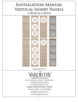
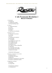
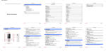
1
Guardian Easytrack System
3-Post Assembly
®
Model 93000
Installation
&
Instruction
Manual
Introduction
2
TABLE OF CONTENTS
Introduction ..........................................................................................
2
Important Safeguards ..............................................................................
3
Requirements .........................................................................................
4
Before You Begin ...................................................................................
5
Kit Contents & Part Numbers ....................................................................
6
Assembly of 3-Post System.......................................................................
6
Disassembly of 3-Post Sytem ....................................................................
9
3-Post Specifications............................................................................... 10
Maintenance .......................................................................................... 11
Troubleshooting...................................................................................... 13
Easytrack Products & Accessories .............................................................. 14
Warranty ............................................................................................... 15
This manual contains important safety and maintenance instructions. Please read
it carefully before using your Easytrack System and refer to it as often as needed
for safe and efficient use.
If you have questions regarding the safe use and/or assembly, maintenance or specifications of your
Easytrack System, you should call Customer Service at 800-333-4000, 303-218-4600 or from Canada at
800-263-3390.
For service and repair, remember your authorized Sunrise supplier is able to provide the assistance you
need.
Save this manual for future reference.
SUNRISE LISTENS
Thank you for choosing a Guardian Easytrack System. We want to hear your questions or
comments about this manual, the safety and reliability of your Easytrack System and the
service you receive from your Sunrise Medical Supplier. Please feel free to write or call us at
the address and telephone number below:
Sunrise Medical
Customer Service Department
7477 East Dry Creek Parkway
Longmont, Colorado 80503
(303) 218-4600 or (800) 333-4000
FOR ANSWERS TO YOUR QUESTIONS
Your authorized supplier knows your Easytrack System best and can answer most of your
questions about its safety, use and maintenance. For future reference, fill in the following:
Supplier: ___________________________________________________________________
Address: ____________________________________________________________________
Telephone: __________________________________________________________________
Serial #: ____________________________________________________________________
Date Purchased: _____________________________________________________________
3-Post System
Important Safeguards
3
IMPORTANT SAFEGUARDS
Do not operate this equipment without first reading and understanding this manual.
Should you be unable to understand the warnings, cautions and instructions, contact our technical support or your local dealer
before attempting to use this equipment– otherwise injury or damage may result.
Important information is highlighted by these terms:
WARNING– Notices as used in the manual apply to hazards or unsafe practices which could result in serious bodily harm.
CAUTION–
Notices as used in this manual apply to hazards or unsafe practices, which could result in minor personal injury or property
damage.
NOTES–
Highlight procedures and contain information which assist the operator in understanding the information contained in this
manual.
NOTE– The information contained in this document is subject to change without notice.
SAVE THESE INSTRUCTIONS AND KEEP WITH EASYTRACK AT ALL TIMES.
The Easytrack System and its accessories are intended to be used as an assistive device for transferring a person between the
posts. The Easytrack system is only to be used with the Guardian Voyager Portable lift.
USE ONLY AS INTENDED - This product may cause serious injury if not installed and operated according to the instruction manual.
Failure to observe warnings listed below could result in serious injury.
Before You Install the Easytrack
• Carefully inspect product upon arrival. If any pieces are missing or appear damaged, do not install. Contact your local supplier
for further instructions.
• If you are unsure of the strength or stability of your floor and/or ceiling, do not install the Easytrack System - consult you
local supplier.
• Easytrack can not be used with any type of suspended ceiling, including suspended drywall, acoustic tile, etc.
• Installation on a plaster ceiling may cause cracking. Sunrise Medical cannot be held responsible for damage.
• Do not install on a ceiling with water damage.
• Do not over-tighten ceiling plate as this may cause ceiling to crack.
• If flooring is not according to local building code standards, flooring may be damaged.
• Do not install on a sloped floor.
• Do not drop product; may cause breakage.
• Do not completely submerge in water.
• Do not attempt to over-extend the rail past the locking point.
• Do not install product if neoprene on top or bottom plate appears to be damaged or absent.
When the Easytrack is in Use
• Do not hit posts - this might cause unit to become unstable. If posts are hit, reassemble Easytrack System to ensure the
posts are straight.
• If you use a power wheel chair, use extreme care. Hitting posts may cause unit to become unstable. If posts are hit, reinstall
the Easytrack System to ensure the posts are straight.
• Do not lean against posts.
• Do not use the Easytrack System as a swing.
• Refrain from swinging user sideways of rail.
3-Post System
Requirements
4
REQUIREMENTS
Failure to meet requirements listed below could result in serious bodily harm.
Ceiling Requirements
• Install to a rigid ceiling (must have a framework above it).
• Must have a maximum of 24" (610mm) between the trusses in the ceiling.
• Ceiling must be made of wood or 1/2"(12.7mm) sheet rock or thicker.
• Ensure ceiling and floor are clear of any dust, grease, water or any foreign substance.
A build-up of nicotine, grease or water on the ceiling will affect the integrity of
the Easytrack System.
• Installing a post directly under a joist or truss is not required, but preferable.
24" max
Joists
1/2" min.
Joists
Suspended
wire or rods
Sheet rock
or tile
Sheet rock
Floor Requirements
• Ensure flooring meets local building code standards. (Termites or water damage may
affect the structure of the floor).
• Ensure floor is clear of any dust, grease, water or any foreign substance.
• Floor must not have a slope of more than 0.5 °. See drawing below to determine the
floor slope. Use a level or contact a contractor if unsure of floor slope.
X
12" (300mm)
24" (600mm)
36" (900mm)
48" (1200mm)
Y
0.10" (2.6mm)
0.21" (5.2mm)
0.31" (7.9mm)
0.42" (10.5mm)
• Ensure posts are straight using the level provided; failure to do so may cause injury.
• Every month a maintenance check should be done to ensure all posts are level. (See
"Maintenance" section in this manual).
• Make sure the padded surface of the top plate and foot plate are kept clean and are
intact.
• Protect the Easytrack System and its accessories during transport.
3-Post System
B e f o r e Yo u
Begin
5
16–18"
36"
Figure 2
Figure 1
" m
20 10 m
]
[2130 – 2746 mm]
[5
7
4
[19 .8"
00 – 1
– 3 24
16 .5"
0m
m]
[
8" 200
1. Survey the room where you plan to
install the Easytrack System. Make
sure the room meets all the specifications outlined in "Requirements".
2. Use the measurements below to
determine the best place to put the
Easytrack System:
a. Over a bed - approx. 36-40"
(915-1020 mm) from the head of
the bed (Figure 1).
b. Over a tub - approx. 16-18"
(400-460 mm ) from the end of
the tub (Figure 1).
c. Allow 36" (1000 mm) of open
area for transfer working space
(Figure 2).
d. Transfers should only take place
between the Easytrack System
posts (Figure 3).
3. Though it is not a requirement to
place the posts directly under a joist
in the ceiling, it is preferable. It
does not matter which direction the
top plate is facing (Figures 4 & 5).
84" – 108"
Read "Requirements" and
“Important Safeguards” before
attempting to assemble the
Easytrack System.
36–40"
BEFORE YOU BEGIN
]
m
8" 00 m
2
m
m
" ]
4.8 mm
20
[1
]
[
Figure 3
PREFERABLE
OK
Joists
Joists
Easytrack
post
OK
Figure 4
Sheet
rock
Easytrack
OK post
Sheet rock
Easytrack
post
Figure 5
3-Post System
Assembly of 3-Post System
6
EASYTRACK 3-POST SYSTEM
KIT CONTENTS & PART NUMBERS
(Figure 6)
Description
1 Pivoting extendable
rail w/standard trolley
2 Extendable rail
w/swivel trolley
3 Pivot post
4 Post top for pivot post
5 Standard post
6 Blue locking handle
7 Round blue cap
8 Allen key
9 Clip-on level
10 Top plate
11 Round foot plate
12 Blue plastic strips
(2/post)
13 Flat blue cap
14 C-H protector
15 Swivel trolley
16 Standard trolley
Set screw for rail
stopper (not shown)
Part #
Qty
1
900-0850
1
900-0800
??
N/A
900-0500
N/A
900-0720
900-3280
900-0600
900-0400
900-0350
1
1
4
2
3
3
1
1
3
3
900-0230
900-1050
900-0780
900-0900
900-0650
6
1
1
1
1
2
16
5
6
14
7
8
13
9
12
10
11
Figure 6
900-4580
Required:
Step ladder
Tape measure
An assistant
1. Decide where you will place your
pivot post and the other two standard posts. There must be a minimum
of 75" (1.90 m) of space between
each of the standard posts and a
minimum of 21.3"-55.1" (5401400mm) between the standard posts
and the nearest wall (Figure 3).
NOTE– Posts are not the same - see Figure 6 for
more details.
2. Remove the round blue plastic caps
from the top of each post by pulling
them away from the post (Figure 7).
3. Remove the blue plastic strips from
each side of the posts. Take one end
and pull gently (Figure 8).
4. Place one round foot plate on the
floor where you want to place the
pivot post of the Easytrack System.
3-Post System
4
15
ASSEMBLY OF 3-POST SYSTEM
Tools
•
•
•
3
Figure 7
Figure 8
Assembly of 3-Post System
5. Take the pivot post out of the box
and the post top for pivot post.
Insert the post top into the post
until it snaps into place (Figure 9).
6. Take top plate and clip-on level out
of the box. Place the clip-on level
onto the post at approximately waist
height (Figure 10).
7. Place the post onto the foot plate
and press down to tighten. Pay
attention to the shape of the post
and foot plate before pressing down
onto the foot plate.
8. Place the top plate into the top of
the post, pressing firmly and evenly
downward until the top plate "clicks"
into place (Figure 11).
9. Extend the post quickly towards the
ceiling by pulling the top portion
and holding the bottom portion.
The post should be within 3" (76
mm) of touching the ceiling. If the
top of the post is more than 3" (76
mm) from the ceiling:
a. Raise the top portion of the post
slightly (Figure 12).
b. Press in metal pin on both sides
of the post (Figure 13).
7
Figure 10
Figure 9
“Click”
Figure 11
Figure 12
Figure 13
Figure 14
CAUTION– Metal pins cannot be pressed in
when there is downward pressure on
them. Pressure must be released to
press in pin.
c. Pull top portion of post up
towards the ceiling.
d. Repeat until the top of the post
is less than 3" (76 mm) from the
ceiling.
10. Lift the blue locking handle out of
the lower portion of the post. Using
the blue piece as a handle, twist the
post as follows (Figure 14):
a. Turn the top portion counterclockwise.
b. Hold the bottom portion firmly.
11. Before the Easytrack post tightens
against the ceiling, check the clipon level to make sure the bubble is
in the center of the circle. Tilt the
post until the bubble reaches the
center of the circle (Figure 15).
Bubble
Figure 15
Make sure clip-on level is fully
attached to the post. Failure to
attach level properly could give an
incorrect reading. Level should
"click" into place.
3-Post System
Assembly of 3-Post System
8
12. Once the bubble is in the center of
the clip-on level, continue to tighten ONLY until the red zone at the
top of the post is no longer visible
(Figures 16-A & B).
Red zone must not be visible for
the post to be safely secured.
o not over-tighten the post.
Tighten only until red zone disappears. Over-tightening post may
cause damage to the ceiling.
Figure 16-A
Figure 16-B
Figure 17
Figure 18
13. Remove the level from the post by
sliding it up off the bottom portion
of the post. Slide the blue locking
handle down to fit into the bottom
part of the post to lock the post in
place (Figure 17).
14. Repeat steps 4-12 for second and
third posts.
NOTE– Once the blue locking handle is pressed
into the lower portion of the post, the
post can still be turned as a whole
except top and foot plates. This will not
lower post. The post must turn to enable
you to attach the rail.
NOTE– Make sure the three posts are far enough
away from each other to allow the rail to
attach (75" (1.90 m)).
15. Get the Extendable Rail with swivel
trolley.
16. Place the end of the rail marked
"Step 1" onto one standard post
(not the post designated to be the
'pivot' post) (Figure 18). If pins on
top of post are not facing in direction desired, place rail onto pins and
rotate post to desired direction.
17. Raise the rail slightly and extend the
rail to the second standard post (not
the post designated to be the 'pivot'
post) (Figure 19).
NOTE– Tilt the rail upward (45∞) to latch the
rail onto the post (Figure 18).
18. Latch the end of the rail marked
"Step 2" onto the second post. The
rail should "click" in place. Press up
on the rail to make sure it is locked
into place.
NOTE– Do not squeeze sides of rail together
when attempting to extend or contract
the rail. Squeezing the rail makes it more
difficult to slide.
19. Take the Pivoting Extendable Rail
with standard trolley out of the box.
a. Take the flat blue cap off of the
end of the rail (Figure 19).
3-Post System
Figure 19
Assembly of 3-Post System
b. Find the end stopper from inside
the top of the rail. The top portion is the section without the
small trolley in it (Figure 20).
c. Using the Allen key provided,
loosen the stopper in the upper
portion of the rail and slide it
out of the rail (Figure 21).
20. Place the end of the rail with the
hooks onto the pivot post (Figure 22).
NOTE– Tilt the rail upward (45°) to latch the
rail onto the post.
21. Extend the rail and thread the
wheels of the trolley through the
upper portion of the rail (Figure 23).
22. Continue to extend the rail through
the metal U-shaped attachment.
Rail should extend a minimum of
21.3-55.1" (540-1400mm) beyond
the U-shaped attachment.
23. Add the stopper to the top portion
of the rail.
a. Place the stopper in the upper
portion of the rail with the rubber "bumper" leading (Figure
24). Slide stopper so it is
approximately 1" (25 mm) from
the end of the rail.
b. Using the Allen key, tighten the
stopper in place.
c. Slowly move the rail from post to
post to make sure it moves freely.
If it does not move freely, the
rail needs to extend further out.
9
Figure 20
Figure 21
Figure 22
Figure 23
Figure 24
Figure 25
CAUTION– Make sure the stopper is snug. DO
NOT OVER-TIGHTEN.
d. Snap the flat blue cap onto the
end of the rail (Figure 19).
24. Place one round blue end cap on the
top of each post (Figure 25).
NOTE– Put the level and the Allen Key in a safe
place as you may need them in the future.
25. Slide the blue plastic strips into the
sides of the posts by pinching the
strip on each side to press it into
the grooves. Start at the bottom of
the post (Figure 26).
26. See Figure 27 for photo of assembled
3-Post Easytrack System.
Figure 26
3-Post System
Disassembly of 3-Post System
10
BEFORE USING THE EASYTRACK SYSTEM GO THROUGH THE FOLLOWING CHECKLIST:
✓
✓
✓
✓
✓
✓
✓
Make sure the red zone on top of all posts are not visible.
Make sure the posts are straight. (Did you use the clip-on level?)
Make sure the rail is locked into place (see step 15) and that it looks level.
Make sure the stopper is snug (see step 22b).
Make sure the pivoting rail slides smoothly from side to side.
Check your installation against Figure 27.
Is the blue locking handle secured down into the lower portion of both posts?
DISASSEMBLY OF 3-POST SYSTEM
Ensure no one is in the lift and remove the lift from the Easytrack before adjusting or disassembling the Easytrack System.
Tools Required:
• Step ladder
• An assistant
1. Remove plastic strips from the sides of the posts. To remove, take one end of the
strip and pull outward gently (Figure 8).
2. Remove the round blue caps from the ends of the rails by pulling them away from the
post (Figure 7).
3. Using a step ladder,
a. Remove the flat blue end cap from the end of the pivoting rail (Figure 19).
b. Take the Allen key and loosen the stopper inside the upper portion of the pivoting rail. Remove the stopper from inside the rail (Figure 24).
4. Slowly contract the rail so the 4-wheeled trolley is exposed. Once the rail is free of
the trolley, lower the rail slightly and contract the rail all the way in (Figure 23).
5. Tilt the rail (45°) and lift the other end off of the pivoting post (Figure 22).
Figure 27
Figure 28
NOTE– Do not squeeze sides of rail together when attempting to extend or contract the rail. Squeezing
the rail makes it more difficult to slide.
6. Place the stopper back into the upper portion of the pivoting rail and tighten with
the Allen key (Figure 21). Put the flat blue end cap back onto the rail.
NOTE– Place the rail in a box or bag to protect it from dust and/or other damage.
7. Using a step ladder, reach under the section of the remaining rail labeled "Step 2"
and pull the blue tab away from the post slightly to release the lock on the rail
(Figure 28).
8. Push end of rail to contract the rail and tilt the rail downward (45°). The other end
of the rail should easily be released from the post (Figure 18).
9. Place the rail in a box or bag to protect it from dust and/or other damage.
10. To remove the post, slide the blue locking device up out of the bottom part of the
post to unlock it.
11. Loosen the post by twisting as follows (Figure 29):
a. Turn top part of post to the left.
b. Hold the bottom part of post firmly.
12. Once the post is loose enough to allow you to move the post, slide the top portion
of the post down:
a. Press the blue locking device back into the bottom part of the post.
b. Raise the top portion of the post slightly (Figure 12).
c. Press in metal pin on both sides of the post (Figure 13).
d. Push top portion of post downwards.
e. Repeat until the metal pins are no longer visible and the top of the post is only
6-8" (152-200 mm) above the blue locking handle.
13. Remove the top plate from the post by pressing up evenly.
3-Post System
Figure 29
Specifications / Maintenance
11
NOTE– Metal pins cannot be pressed in when there is downward pressure on them. Pressure must be
released to press in pins.
14. Remove the post from the foot plate by stepping on both sides with your feet and
pulling the post up.
15. Place all pieces into a box or bag to protect them from dust and/or damage.
16. Repeat steps 11-16 for the second and third posts.
NOTE– Put the level and the Allen key with the rest of the Easytrack System for the next time you
need to assemble it.
SPECIFICATIONS
Item Number.................................93000
Weight Capacity .............440 lbs. (200 kg)
" m
20 10 m
]
[5
74
[19 .8"
00 – 1
–
2
Length of Rail......................74" – 124.5"
(1900-3160mm)
31 4.5
60 "
mm
]
Length of Posts ......................84" – 108"
(2130-2745mm)
[2130 – 2746 mm]
84" – 108"
Material.....................Anodized Aluminum
Weight.........................93.5 lbs. (42.5kg)
Ceiling Plate ......................20" (510 mm)
Floor Plate........................4.8" (120 mm)
[
8" 200
]
]
m
8" 00 m
2
m
m
" ]
4.8 mm
20
[1
[
MAINTENANCE
Maintenance must be performed only by qualified personnel.
Failure to follow maintenance instructions below when indicated could result in
injury or damage.
Periodic inspection should be performed by a person who is suitably and properly
qualified and well acquainted with the design, use and care of the Easytrack
System.
Inspection should be carried out both routinely (at least as often as specified)
and as necessary. All defects and damage that have lead to corrective actions
should be noted, signed and dated by the inspector. Defects and resulting actions
should be reported in writing to your supplier.
3-Post System
Maintenance
12
Upon
1.
2.
3.
4.
5.
receipt of your Easytrack System:
Make sure you received all components listed in Figure 6.
Inspect all parts for possible damage in transit.
Ensure all components are in working order.
Arrange for repair/replacement of any faulty parts.
Keep a log of any repair/replacement required.
Before each use of the Easytrack System:
1. Make sure posts are straight. If they do not appear straight, use level to check. If
posts are not straight, remove rail (see Disassembly) and re-install posts (see
Assembly).
2. Ensure that the red zone on top of the post (under the top plate) is not visible.
3. Check that the rail is secured in place. Press up on the rail to make sure that the rail
is locked onto the post.
4. Check for any appearance of damage. If there is apparent damage, do not use the
Easytrack System.
Every month:
1. Use level supplied to ensure all posts are straight.
2. Clean inside of rail with a damp cloth to ensure there is no dust or grease build-up
inside of rail.
3. Make sure the red zone is not visible. If red zone is visible, tighten posts according
to assembly instructions.
4. Check to ensure you still have all your original parts. If any parts are missing they
should be replaced before using the Easytrack again.
5. Check to make sure that the trolley in the rail moves freely. Trolley may need to be
cleaned or replaced.
6. Check for the appearance of rust. If rust is starting to appear, simply scrub the piece
clean.
7. Examine all joints and pieces for wear and fatigue. Replace any part that looks damaged or worn.
8. Document inspection and any repairs.
If equipment is moved on a regular basis:
1. Make sure all components are accounted for.
2. Check "Requirements” and “Important Safeguards" before reinstalling the Easytrack
System.
3. Make sure the padding on the foot and top plate is clear of any foreign substance
and is not damaged. If neoprene (rubber) on either top or bottom plate appears
damaged, the plate must be replaced.
4. Make sure the level is still working.
5. Look for signs of wear or breakage on all parts. Replace any parts that appear worn
or damaged.
Follow guidelines in your portable lift manual for maintenance and procedures on
the lift.
3-Post System
Tr o u b l e s h o o t i n g
13
TROUBLESHOOTING
PROBLEM
1. Trolley moves substantially on its own when
the Easytrack System is fully assembled.
CORRECTION
1. Are posts, straight? Use level (see assembly instructions step 11).
2. Are the rails secured to the posts? Press up on the rail to make sure that the rail is latched onto the
post.
3. Is the ceiling level? An uneven ceiling will make the rail uneven. See "Requirements" section in
manual.
2. Extended rail comes completely apart during
assembly.
1. Rail has been extended too quickly/forcefully. Rail was pulled past the locking device.
2. Check locking device inside rail (top of rail above the trolley) to make sure it is not damaged.
Replace trolley if damaged. See "Easytrack Kit Contents & Part Numbers" section of manual.
3. Put rail back together at a slight angle and slide together.
4. Slowly extend rail out again to make sure locking device clicks into place.
5. Slowly compress rail again.
3. Not able to push pin to assemble/disassemble post.
1. Is the post still tight against the ceiling? Release pressure on posts by unscrewing blue locking
device. See Disassembly instructions step 11.
2. Are you lifting the upper portion of the post slightly to release pressure? Raise upper portion of post
first and push the pin in. See Assembly instructions step 9 or Disassembly instructions step 12.
4. Not able to tighten post enough to hide red
zone.
1. Have you extended the post enough? Unscrew using the blue locking handle (see Disassembly
instruction step 10), slide post up one or more notches, then screw the upper portion of the post to
tighten. See Assembly instructions step 10. If the post has been "unscrewed" to the maximum and
will not turn anymore, reverse direction to shorten the post several inches, then slide the post up
another notch. See Assembly instructions steps 9-10.
2. Are you holding the bottom portion of the post firm while twisting the upper portion of the post
towards the right? See Assembly instructions step 10.
3. Is the blue locking handle up out of the lower portion of the post when turning the upper portion to
the right? See Assembly instructions step 10.
5. Posts do not appear stable.
1. Is red zone still visible? See Assembly instructions step 12 and Troubleshooting problem #4.
2. Is neoprene (rubber) on either top plate or foot plate damaged or dirty? Clean both foot plate and
ceiling plate with soap and warm water. Make sure they dry completely before reassembling post.
3. Replace foot plate(s) or top plate(s) if neoprene is damaged.
4. Is ceiling clean? Clean ceiling and/or floor. See "Requirements" section of manual.
6. Trolley does not roll in rail smoothly.
1. Is rail clean? Clean rail with damp cloth.
2. Is trolley centered in rail? Re-center trolley.
3. Is the trolley damaged? Replace trolley. See "Easytrack Kit Contents & Part Numbers".
7. Pivoting rail does not slide all the way over
to one or both sides.
1. Is the pivoting rail extended far enough beyond the other rail? Lengthen pivoting rail, by pulling further.
2. Is the pivoting post too far from the two standard post? If the pivoting rail can't reach the swivel
trolley rail, you need to decrease this distance. Follow Disassembly instructions and reassemble the 3post Easytrack. See Figure 3 for information on dimensions and layout.
3. Does the pivoting rail need to be more centered between the two standard posts (Figure 30)?
Pivoting post may need to be moved so it is more centered between the two standard posts. Follow
Disassembly instructions and reassemble 3-post Easytrack.
8. Pivoting rail seems to be at an angle and rail
slides freely towards one direction.
1. Is the ceiling level? See " Requirements" section of this manual for more information.
2. Is the pivoting rail properly attached to the pivoting post? See Figure 3make sure that the proper post
was used. The pivoting post and standard post are not the same.
3. Is the extendable rail with swivel trolley secured on the post? Push up on the rail to ensure it is
locked.
3-Post System
Easytrack Products & Accessories
14
EASYTRACK PRODUCTS & ACCESSORIES
Easytrack 2-Post System...........................................................................
92000
Easytrack 4-Post System...........................................................................
94000
Easytrack 2-Post with Tub Bracket .............................................................
92001
Easytrack 3-Post with Tub Bracket .............................................................
93001
Easytrack Portable Carry Bag.....................................................................
92341
3-Post System
Wa r r a n t y
15
WARRANTY
This warranty is extended only to the original purchaser/user of Sunrise products.
Sunrise Medical Inc. warrants its products to be free from defects in material under normal
use and service and will, within the periods stated below, from the date of purchase. If
within such warranty period any such product shall be proven to be defective, such product
shall be repaired or replaced at Sunrise Medical's option. This warranty does not include
any labor or shipping charges incurred in replacement part installation or repair of any such
product. Sunrise Medical's sole obligation and your exclusive remedy under this warranty
shall be limited to such repair and/or replacement.
Lifter including Hydraulics
Accessories on Lifter
Slings
Batteries
Easytrack System
1
1
1
3
1
year
year
year
months
year
For warranty service, please contact the provider from whom you purchased the Sunrise
Medical product. In the event that you do not receive satisfactory warranty service, please
contact Sunrise Medical customer service at 1-800-333-4000.
Do not return products to our factory without prior authorization. Sunrise Medical will issue
a Return Merchandise Authorization (RMA) Number. C.O.D. shipments will be refused; all
shipments to Sunrise Medical must be prepaid. For this warranty to be valid, the purchaser
must present its original proof of purchase at the moment of the claim. The defective unit,
assembly or part must be returned to Sunrise Medical for inspection. The part or components repaired or replaced are guaranteed for the remaining period of the initial warranty.
Limitations and Exclusions:
The above warranty does not apply to serial numbered products if the serial number has
been removed or defaced.
No warranty claim shall apply where the product or any other part thereof has been altered,
varied, modified, or damaged; either accidentally or through improper or negligent use and
storage. Warranty does not apply to products modified without Sunrise Medical's express
written consent, (including but not limited to products modified with unauthorized parts or
attachments); products damaged by reason of repairs made to any component without the
specific consent of Sunrise Medical, or to products damaged by circumstances beyond
Sunrise Medical's control. Evaluation of warranty claim will be solely determined by Sunrise
Medical. The warranty does not apply to problems arising from normal wear or failure to
adhere to the instructions in this manual. Sunrise Medical Inc. slings are void of warranty
if not laundered as per instructions on the Sling Label.
Sunrise Medical Inc. shall not be liable for damages losses or inconveniences caused by a
carrier.
This warranty replaces any other warranty expressed or implicit and constitutes Sunrise
Medical Inc.'s only obligation towards the purchaser. Sunrise Medical shall not be liable for
any consequential or incidental damages whatsoever.
3-Post System
Distributed by:
Sunrise Medical
7477 East Dry Creek Parkway
Longmont, Colorado 80503
(800) 333-4000
In Canada (800) 263-3390
Printed in Canada
© 2001 Sunrise Medical 10.01
900-0610 Rev. A