1
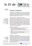
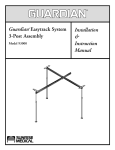
Installation Manual
Vertical Insert Panels
3 High & 4 High
Revised 05/18/2012
Yardistry - North America
Toll Free Customer Support: 1.888.509.4382
[email protected]
www.yardistrystructures.com
Yardistry / Selwood Products - Europe
Customer Support: +44 1284 852569
[email protected]
www.selwoodproducts.com
1
!Important Safety Notice!
•
Yardistry components are intended for privacy, decorative and ornamental use only. Product is NOT
INTENDED for the following:
- A safety barrier to prevent unsupervised access to pools, hot tubs, spas, or ponds.
- Safety railings for elevated platforms or decks.
- As load bearing support for a building, structure, heavy objects or swings. - Used in structures that trap
wind, rain or snow that would create extra load on the product.
•
Permanent structures may require a building permit. As the purchaser and or installer of this product you
are advised to consult local planning, zoning, and building inspection departments for guidance on applicable
building codes and or zoning requirements.
•
Wood is NOT flame retardant and will burn. Grills, fire pits and chimneys are a fire hazard if placed too
close to a Yardistry structure. Consult user’s manual of the grill, fire pit or chimney for safe distances from
combustible materials.
•
During installation, follow all safety warnings provided with your tools and use OHSA approved safety
glasses.
•
Some structures may require two or more people to install safely. Check for underground utilities
before digging or driving stakes into the ground!
General Information: Wood components are manufactured with Cedar (C. Lanceolata) which is protected with
factory applied water-based stain. Knots, small checks (cracks) and weathering are naturally occurring and do
not affect the strength of the product. Annual application of a water-based water repellent sealant or stain will help
reduce weathering and checks.
Keys to Assembly Success
Tools
Required
Warranty: Yardistry products are backed by a 5 year limited lifetime warranty from the date of original retail
purchase
for manufacturing defects
if installed as per •manufacturer’s
• Tape Measure
• #1, #2 and
& #3 Phillips
Open End Wrench installation instructions.
• 3/16” Hex Key
• Carpenters Level
• Carpenters Square
• Claw Hammer
• Standard or Cordless Drill
• Tape Measure
or Robertson Bits
(7/16”, 1/2” & 9/16”)
Patents Pending
or Screwdriver
• Adjustable Wrench
• Ratchet with extension Tools Required
• 1/8” & 3/16” Drill Bits
(1/2” & 9/16” sockets)
• Pencil
• #2 Phillips or Robertson
Bits or Screwdriver
• 8’ Step Ladder
• Safety Glasses
• Adult Helpers
• Safety Glasses
• Adjustable Wrench
Part
Identification
Key
• Carpenters
Level
• 1/8” Drill Bit
On each page, you will find the parts
and
2X A1 Post 2 x 4 x83”
• Ratchet
with extension
• Carpenters
Square
• Pencil
quantities
required
to complete the assembly
(7/16” sockets)
step illustrated on that page. Here is a sample.
• Adult Helpers
• Standard or Cordless
Drill
Symbols
• 1/4” Drill
Bit
Key Number
Part Description, Part Size
• Open End WrenchQuantity
• 8’ Step Ladder
(7/16”)
Throughout these instructions symbols are provided
as
important
reminders
for proper and safe assembly.
Keys To Assemble Success
This identifies information that requires special
attention. Improper assembly could lead to an
unsafe or dangerous condition.
Use
Help
Measure
Distance
Use
Help
Check that set or assembly is properly level
before proceeding.
Pre-drill 1/8” & 3/16” Bit
Where this is shown, 2 or 3
people are required to safely
complete the step. To avoid
injury or damage to the
assembly make sure to get help!
Check that assembly is square
before tightening bolts.
Pre-drill a pilot hole
before fastening screw
or lag to prevent
splitting of wood.
Square
Assembly
Tighten
Bolts
This indicates time to tighten bolts, but
not too tight! Do not crush the wood.
This may create splinters and cause
structural damage.
Use a measuring tape to assure
proper location.
No
CAUTION – Protrusion Hazard
Use
Level
2
Yes
If Bolt protrudes
beyond T-Nut
4 x 8 Arbor Roof Kit includes:
A Kit
Y50113-020
de
techo de
Material ListNominale
la pérgola de 4" x 8" incluye:
Kit de Toit Arbor 4 x 8 po inclus:
2" x 6"
2" x 3"
1" x 6"
(4) 2 x 6 x 13½"
B
A
Y50113-029
Y50113-034
(4) 2 x 6 x 36-13/16"
P_1
C
D
Y50113-031
Y50113-036
(2) 2 x 4
Actual
Actuel
1½" x 3½"
1" x 2½"
ǫ" x 5½"
Note: Panel assembly in this instruction is
shown as a 2 or 3 High Lattice Panel with a
1 High X Topper. Depending on kit purchased,
images may not be accurate. Please see front
cover for what your final set-up should look like.
(2) 2 x 4 x 80"
B
Nominal
Nominale
2"Actuel
x 4"
1½" x 5½"
5/4"
3"
1½" xx2½"
x 41ǩ"
(4) 2 xY50113-030
6 x 37"
C
(6) 5/4 x 3 x 54¼"
Y50113-037
4 High X Insert Panel - YM11566
(1) One High X Topper or,
S1
(4) 2 x 6 x 81Ǭ"
4 High Lattice / X Insert Panel - YM11564
(1) One High Lattice
(36)Topper
#10 x 1"or,
4 High Lattice Insert Panel - YM11565
E (1)Y50113-032
One High Faux Glass Topper
4 High Faux Glass Insert Panel - YM11666
(2) 1 x 6 x 80½"
P_3
3 High X Insert Panel - YM11668
Y50113-022
F
3 High
Lattice / X Insert Panel - YM11669
(12) 5/4
x 3 (Y70813-000)
3 High Lattice Insert Panel - YM11667
(4) 2 x 6 x 21ǫ"
3 High Faux Glass Insert Panel - YM11670
Y50113-024
(sold separately)
(4)(se
2 x 6vende
x 80ǩ" por separado)
(vendu séparément)
G
H
YP21012
4 x 4 Post Top Connector
Y50113-035
P_2
(22) 2 x 3 x 34¾"
I
Conectores superiores
de postes de 4 x 4
Attaché a Poteau 4 x 4 po.
Y50113-033
(11) 2 x 3 x 83½"
(20) 1/4"
WT
(42) 1/4" x 2"
WL
*Optional- May Not
be Included
S4
G
S1
S2
S3
(12) Panel Clips
(22) 1/4"
(44)
(4)
2 #10
x 4 xx1"12”
Gusset
(8) #8 x 1½"
(34)#8
#8 x
(8)
x 3½"
3” Wood Screw
S7
S4
S4
(64) 1/4"
YP11012
2 x 4 Beam End
2x3
Extremos de viga de 2' x 4'
Poteau d’extrémité 2 x 4 po.
2
YP11011
4 x 4 x 96" Post
(1) Two/Three High X Panel or,
Postes de 4 x 4 x 96"
Poteau 4 x 4 x 96 po.
(1) Two/Three High Lattice Panel or,
(1) Two/Three High Faux Glass Panel
3
3
S4
S5
S5
S7
#8 x 2 1/4” Wood Screw
(22) 2 x 3 (Y70813-001)
S6
S7
S7
#10 x 1” Pan Head Screw
S5
#8 x 1 1/2” Wood Screw
S5
S6
(2) Top and Bottom Rail - 20”
R
S6
Step 1- Assemble Panels
1. Remove the upper metal connectors on both sides of P_3 - Three High_Panel. Reattach the metal connectors
to P_3 by securing the bottom two holes of the metal connectors to the top two holes on P_3 so that the metal
connectors stick out from the top. Slide P_1 – One High_Topper between the two protruding metal connectors
on the top of P_3. Attach the metal connectors to P_1. (Fig. 1A)
*Ensure Panels are oriented correctly! (Fig. 1B)
2. Secure panels with a S4 - 2 1/4” Wood
Screw the location indicated by the large
arrow in the direction of the arrow.
Note P_1
orientation of keyhole.
d reattach using
n panel.
Tenga en cuenta la orientación
del agujero de la cerradura.
y vuelva a
eros
Notez l'orientation de l'encoche
en trou deserrure.
accordement et
n des deux trous
été percés à
Pilot holes to the right
Fig. 1B - Filler Strips on Bottom
of Panel!
x1
Fig. 1A
Do not remove Small Connector
P_3
No retire los conectores
Ne retirez pas les petites pièces d
raccordement.
4x
P_1
One High _Topper
4x
P_3
Three High _ Panel
4x
4
S4
#8- 2 1/4” Wood Screws
Step 2- Attach Panel Clips to posts
3 High Panel Assembly
(4 high panel Assembly instruction located on next page)
P
lflat
plpeesurface
csurface
flnflnai a
.1
1.
aain
P-.4x4
4x4Post
Poston
onits
itsside
sideand
andposi
pos
iPliC
l1elennaPost
PPnnooon
ion
tiitsisoits
ppside
dside
ddisisposition
sposition
PP44xx1.
44
-On
ccin
plpesurface
flflaannPOO
1
1.
place
its
Clips
pddnnaaeeddisissstitinnootstsooPP44xx4
1.
4-On
-On
Peecaa
caaflat
caafrfu
russtatplace
a
isnspnO
pPO
lC
4x4
.4x4
aPost
o
dnnaaeand
eand
stitinnootstsoPanel
oPanel
Clips
-POn
Peea
flat
alflat
ecsurface
caafrfruussta
place
taplace
.1
locations
1A.
Ensure
Panel
aaPPeerruuss1. nnEEO
.A
sseeru
i iddeetatindicated
didnni4x4
ie
tPost
cFigures
and1A.
1A.
EnsurePanel
Pane
tiattnaFigures
ecoeiolrirlooon
eerra1its
pp
iliC
le
nn
a
n
1Clips
ddnnaa1are
sseeroriented
glocations
iF
a
ccididnniindicated
tia
locations
indicated
in
1A.
Ensure
Panel
are
oriented
.n
A11addnflat
naa11surface
rug
giFiFnn
acciPissnd
node
oin
n
a1sand
sand
lC
leand
aPPe
erruuss
nEE.A
.A
1Clips
1
ru
ulocations
gin
iFnlocations
ni iddeetindicated
taindicated
issnnoin
oiin
tFigures
acFigures
cool l in Figure
11and
place
side
position
Panel
Clips
1.Ensure
!as
s
m
aarrggaaiD
nniDiagrams!
nnwwoohhssssaa
!as
aarrggaaiD
nniDiagrams!
nnwwoohhssssaa
shown
in
as
!sClips
m
shown
iDin
iDiagrams!
as
!ssm
shown
mshown
iD
inin
iDiagrams!
Ensure Panel
are
oriented
as shown in Diagrams!
ccaPanel
plpeebbdClips
luluoohhsshould
ssppiliC
eglbe
Pg
.2
thecentre
centreofofthe
thepost
posto
l lethe
hht trcentre
eof
tthe
epost
ccethe
hht tnleading
i idde2.
pledge
eebbd
luluoohhsshould
ssppiliC
elbe
PP.2
Clips
in
the
centre
the
leading
oppeehht tfofoeertrntneecceehht tnni idde2.
e2.
alPanel
d
sshould
lCelebe
e
gndn
daeplaced
a
eplaced
Pgn
n.i2didaaein
e
e
ro
otstsooppof
ehh
the
tfo
fopost
errtn
tneor
eor
e
n
ec2.
caPanel
alPanel
pedge
Clips
dClips
sshould
lClbe
ennaplaced
aplaced
.2 ininthe
anel
be
placed
the
the
3/8” away
or
eehht tmmoor2.
frfyyaP
aammcc5Clips
8
/of
3/3the
1the
ddlulshould
ofaotstscentre
of
3.5cm
awayfrom
fromthe
theside
sid
oor
pp3.5cm
e3.5cm
dthe
hfrom
t tm
ror
wwaaleading
m
5the
rpost
””8of
3
1the
eeb
ddlulshould
hhssppishould
libe
clcbe
eeh
o
clip
should
1tsthe
3/8”
from
the
ofccthe
as
aww
5.3.3ro
ro”should
”8of
1eebclip
b
uo
ohhssppilicbe
lbe
cein
eh1h
t3/8”
sfa
oor
ehht tfo
fof
oeaway
eaway
disiseepost
h
moothe
rf fyya
side
aside
of
m
5.3
.3post
rooedge
8/as
/3the
1of
clip
bclip
uoshould
oclip
1h1t3/8”
tf3/8”
fobe
oror13.5cm
3.5cm away from
the
2.side
nni inthe
showninin.Fig.
2.nni innwwoohhss
2
F
shown
in.Fig.
Fig.
shown
in
2.g.giF
2.
i2.
Fof
nwwoohpost
hss as shown in Fig. 2.
shown
.Fig.
2.g
.gi2.
iF
aahhtitw
crcsskkra
,e,With
nniplace,
C
nnain
PPplace,
hhtscrew
iltW
.-3.mark
Panel
place,
screwholes
holeswith
withaapen
pe
liliW
ddnscrew
aalilcicwith
nneholes
ppaa
twith
itw
h
e
ccaalplpPanel
n
i issppilClips
PPplace,
h
.mark
3
3.
With
Panel
in
place,
screw
holes
pencil
iws3.
seelolW
ohhw
weerPanel
ramm
3.
eccaalplin
pPanel
issppiliClips
lClips
Clelemark
a
lrirdd
-emark
3errppholes
n
e
with
iwsse
aa
elopencil
lo
hwweerpre-drill
and
rcand
csskkrpre-drill
rapre-drill
am
3.
m3.,With
,eWith
nwith
iC
lClips
C
enna
inain
htitW
iWbit.
.3mark
screw
ith
Clips
ahhpencil
and
holes
alel1/8”
drill
(Not
)
d
e
d
i
v
o
r
p
t
o
N
(
.
t
i
b
l
l
i
r
d
”
8
/
1
a
h
t
i
w
s
e
l
o
h
holes
with
a
1/8”
drill
bit.
(Not
provided)
)
d
e
d
i
v
o
r
p
t
o
N
(
.
t
i
b
l
l
i
r
d
”
8
/
1
a
h
t
i
w
s
e
l
o
h
holes
with
a
1/8”
drill
bit.
(Not
provided)
)
d
e
d
i
v
o
r
p
t
o
N
(
holes
.
t
i
b
l
l
i
with
r
d
”
8
a
/
1
1/8”
a
h
t
drill
i
w
s
bit.
e
l
o
h
(Not
provided)
)
d
e
d
i
v
o
r
p
t
o
N
holes
(
.
t
i
b
l
l
with
i
r
d
”
8
a
/
1
1/8”
a
h
t
drill
i
w
s
bit.
e
l
o
h
(Not
provided)
provided)
11eeru
t4.
ool lnni issppPanel
iPanel
liC
aClips
c8ce
4.S
indicatedininfigure
figure11an
an
#locations
AA11ddnnaa11in
eerfigure
eand
id
ssnnoo4.
iS7tS7a
o#8
ilPanel
aClips
cclocations
eelocations
SS.4
in
locations
indicated
in
1A
ruggfifinni iddeetataccididnni issnnooi4.
iatacSecure
cSecure
lClelennClips
aPP1e1erxu
rxin
u8
#
eS-S-7.7S
4hhtitw
iwindicated
rufigure
uggfifinni1i1ddand
eta
tacc1A
idnniwith
iwith
i4.
tacSecure
cSecure
ol#8
lnnixixss1p1p
Panel
iC
lClelennClips
aPPeerin
ruuin
.4
indicated
4. Secure Panel1/2”
Clips
locations
indicated in figure 1 and 2 with S7 - #81/2”
x 1wood
1/2”
wood
screws.
.s.in
rcrcssddooooww”2
1/2”
wood
.s.swwescrews.
1/2” wood
wood
swwescrews.
escrews.
”2/1/1
erscrews.
rccssddooooww””22/1
/1
Fig. 1
wweeiViVppooTT
Top
View
w
Top
View
weeiV
iVppooTT
Top
View
TopView
View
Top
A
B
C
D
B
D
A
D
B
A
C
C
A
B
A
B
C
C
A
B
B
A
B
A
D
A
B
D
Front
FrontView
View
wweeiV
iVtn
tnoorF
rF
””44//11(142.9cm)
6655
)m
56
(142.9cm)
)mcc99.2
.56
24411(1/4”
(1/4”
11( ( ””44//11 6655
)m
(101.6cm)
)mcc66.1.10011(( ””0044
40” (101.6cm)
40”
)m
)mcc66.1.10011( ( ””0044
(25.3cm)
(25.3cm)
)m
)mcc33.5.522( (
)m
)mcc33.5.522((
Fig. 2
1 3/8”
(3.5cm)
Pre-drill holes and secure with S7- #8 x
1 1/2” Wood Screws
4x
P
4x4 Post
12x - Panel Clips
24x S7 #8 x 1 1/2” Wood Screw
5
FrF
561/4”
1/4” (142.9
(142.
56
(101.6cm)
40” (101.6cm)
40”
(25.3cm)
(25.3cm)
Step 2- Attach Panel Clips to posts
4 High Panel Assembly
1. On a flat surface place P- 4x4 Post on its side
and position Panel Clips in locations indicated
in Figure 1. Ensure Panel Clips are oriented
as shown in Diagrams!
2. Panel Clips should be placed in the centre of
the post or the leading edge of the clip should
be 1 3/8” or 3.5cm away from the side of the
post as shown in Fig. 2.
Top View
C
A B
3. With Panel Clips in place, mark screw holes
with a pencil and pre-drill holes with a 1/8” drill
bit. (Not provided)
4. Secure Panel Clips in locations indicated
in figure 1 and 2 with S7- #8 x 1 1/2” wood
screws.
Fig. 1
Front View
75”
(190.5cm)
40”
(101.6cm)
Fig. 2
1 3/8”
(25.3cm)
(3.5cm)
Pre-drill holes and secure with S7- #8 x
1 1/2” Wood Screws
4x
P
4x4 Post
12x - Panel Clips
24x S7 #8 x 1 1/2” Wood Screw
6
D
Step 3 -Attach Panels to Posts
lace panel assemblies on posts as shown (Fig.1) allowing a 4” gap between the bottom of the post and the
nels1. Pbottom
to
Posts
edge of the bottom rail on the panel assembly. Note: Assemble with help of another adult.
2. With a 1/8” drill bit, predrill holes as shown in figure 2.
3. Fasten the panel assembles to the post and Panel Clips with a S5- 1” Pan Head Screw provided in location of
arrows. (Fig. 1)
4. Repeat for each post configuration.
STEP 3 -Attach Panels to Posts
4 High
STEP 3 -Attach Panels to Posts
Fig. 1
3 High
x1
Fig. 2. Predrill Holes and Fasten
with S5- 1” Pan Head Screw
12x
S5
4” (10.2cm)
1” Pan Head Screw
7
4” (10.2cm)