1
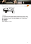
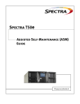
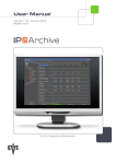
Spectra T200, T380, T680, T950, and T-Finity Drive Installation or Replacement Instructions SpectraLogic.com Copyright Copyright © 2008 – 2010 Spectra Logic Corporation. All rights reserved. This item and the information contained herein are the property of Spectra Logic Corporation. Notices Except as expressly stated herein, Spectra Logic Corporation makes its products and associated documentation on an “AS IS” BASIS, WITHOUT WARRANTY OF ANY KIND, EITHER EXPRESSED OR IMPLIED, INCLUDING BUT NOT LIMITED TO THE IMPLIED WARRANTIES OF MERCHANTABILITY OR FITNESS FOR A PARTICULAR PURPOSE, BOTH OF WHICH ARE EXPRESSLY DISCLAIMED. In no event shall Spectra Logic be liable for any loss of profits, loss of business, loss of use or data, interruption of business, or for indirect, special, incidental or consequential damages of any kind, even if Spectra Logic has been advised of the possibility of such damages arising from any defect or error. Information furnished in this manual is believed to be accurate and reliable. However, no responsibility is assumed by Spectra Logic for its use. Due to continuing research and development, Spectra Logic may revise this publication from time to time without notice, and reserves the right to change any product specification at any time without notice. Part Number Revision History 91010010 Revision B Revision Date Description A November 2008 Initial release B May 2010 Added the T‐Finity library Contacting Spectra Logic To obtain general information Spectra Logic Web Site: www.spectralogic.com United States Headquarters European Office Spectra Logic Corporation Phone: 1.800.833.1132 or 1.303.449.6400 International: 1.303.449.6400 Fax: 1.303.939.8844 Spectra Logic Europe Ltd. Phone: 44 (0) 870.112.2150 Fax: 44 (0) 870.112.2175 Spectra Logic Technical Support Web Site: www.spectralogic.com/support Knowledge Base: www.spectralogic.com/knowledgebase United States and Canada Phone: Toll free US and Canada: 1.800.227.4637 International: 1.303.449.0160 Email: [email protected] Europe, Middle East, Africa Phone: 44 (0) 870.112.2185 Email: [email protected] Deutsch sprechende Kunden Phone: 49 (0) 6028.9796.507 Email: [email protected] Mexico, Central and South America, Asia, Australia, and New Zealand Phone: 1.303.449.0160 Email: [email protected] To obtain library documentation Spectra Logic Web Site: www.spectralogic.com/documents 2 Drive Installation or Replacement Instructions 91010010 Drive Installation or Replacement Instructions This guide provides instructions for either installing an additional drive or replacing an existing drive in a Spectra T200, T380, T680, T950, or T‐Finity library (the library). Illustrations The replacement drive that you received may not look exactly like the drives shown in this document. Most of the figures in this guide show the Spectra T380 library. The relative locations of the components and the procedures are the same for the other libraries unless otherwise indicated.The differences are indicated by library type; for example: Spectra T200, T380, or T680—items indicated with this text refer to any one of these three libraries. Spectra T950 and T‐Finity—items indicated with this text refer to either of these two libraries. User Interface Updates The BlueScale interface changes as new features are added or other modifications are made between firmware revisions. Therefore, the user interface screens on your library may differ from those shown in this document. Drive Bay Assemblies Each drive is mounted on a drive sled which is installed in a drive bay assembly (DBA) in the back of the library. If there are no empty drive bays in your library, you must install a new DBA to accommodate additional drives. Backups cannot continue while you install the new DBA and drive(s). Tape Drive Support This table shows the tape drives supported by the individual libraries. Library LTO-1 LTO-2 LTO-3 LTO-4 LTO-5 T200 Y Y Y Y Y T380 Y Y Y Y Y T680 Y Y Y Y Y T950 Y Y Y Y Y T‐Finity N N N Y Y 3 Prepare for Maintenance PREPARE FOR MAINTENANCE Make sure you fulfill the prerequisites described in this section and familiarize yourself with all the sections in the document before starting. Continuing or Stopping Backups Use the following guidelines if you are installing or replacing a drive in a drive bay assembly (DBA) already in the library. Method Description QIP-attach drives (all libraries) Backups running to all other drives in the library (or partition) can safely continue while you install a new drive or replace an existing one. Direct-attach SCSI drives (Spectra T200, T380, T680) If multiple direct‐attach SCSI drives are daisy‐chained on the same SCSI bus, adding or removing a drive interrupts communications on the bus. Stop backup operations to all of the drives in the daisy chain. Spectra Logic recommends shutting down and powering off the host computer before replacing a drive. Note: Both the T950 and the T‐Finity require a QIP for direct‐attach drive configurations. Direct-attach Fibre Channel drives (Spectra T200, T380, T680) Backups running to other drives in the library (or partition) can safely continue while you install a new drive or replace an existing one, unless the drive you are replacing is the one exporting the library (that is, providing the robotic control path for the partition). If the drive you are replacing provides the control path for the robotics, stop backup operations to the partition. Note: Both the T950 and the T‐Finity require a QIP for direct‐attach drive configurations. Note: Selecting a drive to provide the robotic control path is part of configuring a partition. Refer to the individual User Guide for more information. Ensuring ESD Protection The repair environment for the library must be free of conditions that could cause electrostatic discharge (ESD). To protect the library from ESD, follow these procedures: 4 Place a static protection mat on the work surface used while removing and installing library components. Use a 1‐megaohm resistor to ground the static protection mat. Wear a static protection wrist band whenever you handle library components that have been removed from their antistatic bags. Connect this wrist band to the static protection mat or to other suitable ESD grounding. Keep all components in antistatic bags when not in use. Drive Installation or Replacement Instructions 91010010 Gathering Tools and Supplies Gathering Tools and Supplies You must have the following to complete this procedure: Item Description Supplies ESD protection equipment A Replacement Drive from Spectra Logic Fibre Channel tape drive example SCSI tape drive example IDENTIFY THE DRIVE LOCATION Note: If you are installing an additional drive, rather than replacing a drive, skip to Drive Installation Preparation on page 10. Your backup software, the library, or both may indicate a drive problem. First, identify the problem drive, then check the Drives screen on the library user interface for the drive identifier, and finally, write down the drive identifier for use in a later section. Note: If your library has multiple partitions, use your backup software and the Partition Settings screen to identify the malfunctioning drive. Drives are identified in the library’s BlueScale user interface using the format shown in the following sections. You can also access the back of the library and look for the drive sled status light that blinks amber. Status LED Drive lock Figure 1 The drive sled (SCSI drive sled shown). May 2010 Spectra T200, T380, T680, T950, or T-Finity Library 5 Identify the Drive Location Spectra T200, T380, or T680 Library The user interface nomenclature uses DBAx/Y-DRVx: DBAx is the number of the drive bay assembly (DBA) containing the drive; a DBA holds up to four drives and one Quad‐Interface Processor (QIP). Y is the drive type (LTO, for example). DRVx is the number of the drive bay in the DBA, as viewed from the back of the library. Back panel drive locations and their identifiers (T380 shown) Drive bay opening Drive 3 Drive 4 Drive 1 Drive 2 Drive 3 Drive 4 Drive 1 Drive 2 Drive 3 Drive 4 Drive 1 Drive 2 QIP 3 DBA 3 QIP 2 DBA 2 QIP 1 DBA 1 This figure shows the relationship between the DBA number and the drive locations used in the identifier. Examples 6 If this drive ... Is installed in this drive bay ... Its identifier is ... LTO‐n Drive bay 1 in DBA1 DBA1/LTO‐DRV1 LTO‐n Drive bay 2 in DBA2 DBA2/LTO‐DRV2 Drive Installation or Replacement Instructions 91010010 Gathering Tools and Supplies Spectra T950 or T-Finity Library The user interface nomenclature uses FRx/DBAx/Y-DRVx: FR is the library frame in which the drive is installed and x is the frame number; there can be up to six frames in a cascade. DBA is the drive bay assembly containing the drive, and x is the DBA number; a DBA holds up to four drives and one Quad‐Interface Processor (QIP). Y is the drive type (LTO, for example), and DRVx is the number of the drive bay in the DBA. This figure shows the relationship between the DBA number and the drive locations used in the identifier. The relationship between the DBA number and drive locations is the same for each additional drive frame. Frame 1 Back panel drive locations and their identifiers (T950 shown) Drive 3 Drive 4 Drive 1 Drive 2 Drive 3 Drive 4 Drive 1 Drive 2 Drive 3 Drive 4 Drive 1 Drive 2 Drive 3 Drive 4 Drive 1 Drive 2 Drive 3 Drive 4 Drive 1 Drive 2 Drive 3 Drive 4 Drive 1 Drive 2 DBA 6 DBA 5 DBA 4 DBA 3 DBA 2 DBA 1 QIP 6 QIP 5 QIP 4 QIP 3 QIP 2 QIP 1 Example If an LTO drive is installed in frame 1, DBA2, drive position 4, its identifier is FR1/DBA2/LTO-DRV4. May 2010 Spectra T200, T380, T680, T950, or T-Finity Library 7 Replace or Install a Drive REPLACE OR INSTALL A DRIVE This section describes how to replace an existing tape drive or install an additional tape drive, and contains these steps: Important Preparing the Library (for replacement or installation) Accessing the Drives on page 10 (for replacement or installation) Removing the Malfunctioning Drive on page 13 (for replacement only) Installing the Drive on page 14 (for replacement or installation) When replacing a drive, the new drive must be the same “type” as the one you replace. If the drive to be replaced is the only drive in the partition, the existing partition will be deleted. Preparing the Library Drive Replacement Preparation This section describes how to prepare to replace a drive in the library. Note: If you are installing an additional drive, rather than replacing a drive, skip to Drive Installation Preparation on page 10. If the malfunctioning drive contains a cartridge, attempt to use the BlueScale user interface to move the cartridge to an empty slot before performing the steps in this section. See the individual User Guide for instructions. If you are unable to remove the cartridge, continue with the replacement without removing the cartridge. After you determine which drive needs replacing, follow these steps to shut down the drive so that you can remove it from the library. 1. If the drive is attached to a QIP or if it is a direct‐attach Fibre Channel drive, skip to Step 2. If the drive a direct‐attached SCSI drive, Spectra Logic recommends shutting down and powering off the host computer before replacing the drive Caution Improperly removing a device from a SCSI bus can cause a host computer to crash. If you decide to leave the host running, Spectra Logic is not responsible for any damage to data or equipment. 2. Log into the library with superuser or administrator privileges. 8 Drive Installation or Replacement Instructions 91010010 Preparing the Library 3. Select Configuration > Drives. The Drives screen displays. Figure 2 The Drives screen. Note: The individual drive types are identified by: fLTO refers to Fibre Channel. LTO refers to SCSI. 4. Based on the drive identifier you determined in Identify the Drive Location on page 5, select Replace for the drive that you want to replace. Caution Do not select Remove. This option permanently removes the drive from the partition. When the replacement drive is installed, it will not be assigned to the partition from which the malfunctioning drive was removed. If you select Remove and the selected drive is the only drive in the partition, the partition will be deleted. A Feedback Required screen prompts you to confirm that you want to replace the drive. 5. Select OK. Another Feedback Required screen indicates that the requested drive has been successfully shut down. Important May 2010 Do not respond to the prompt in the Feedback Required screen or perform any other operations from the user interface (either locally or remotely) until you complete the replacement procedure. Responding before you replace the drive will power on and configure the drive you just powered down. Spectra T200, T380, T680, T950, or T-Finity Library 9 Replace or Install a Drive Drive Installation Preparation This section describes how to prepare to add a new drive to the library. If you are replacing a drive, follow the steps in Drive Replacement Preparation on page 8. 1. Log into the library with superuser or administrator privileges. 2. From the toolbar menu, select Configuration > Drives. The Drives screen appears. Figure 3 The Drives screen. 3. Select Add in the location where you want to add a drive. A Feedback Required screen prompts you to confirm that you want to add the drive. 4. Select OK. Important Do not respond to the prompt in the Feedback Required screen or perform any other operations from the user interface (either locally or remotely) until you complete the replacement procedure. Responding before you replace the drive will power on and configure the drive you just powered down. Accessing the Drives This section describes how to access the tape drives. Spectra T200 or T380 Remove the protective cover in order to install or replace drives. 1. From the rear of the library, locate the two knurled screws securing the bottom of the cover to either side of the chassis (Figure 4). 10 Drive Installation or Replacement Instructions 91010010 Accessing the Drives 2. Using your fingers or a #2 Phillips screwdriver, loosen the captive screws that secure the bottom of the cover to the chassis. Cover Knurled screw Figure 4 The rear panel cover and screws (T380 shown). 3. Lift the cover upward and away from the chassis to disengage the two nuts extending from the back of the cover from the holes on either side of the chassis (see Figure 5). Set the cover aside. Top cable cutout Alignment nut Figure 5 Cover alignment nuts (one on each side). Spectra T680 The T680 is shipped and installed in a rack. Access the back of the rack and open the door (Figure 6). Handle (tilt up and out to disengage) Lock Figure 6 The T680 door handle. May 2010 Spectra T200, T380, T680, T950, or T-Finity Library 11 Replace or Install a Drive Spectra T950 or T-Finity The drives are shielded by protective doors. Note: Opening the library’s rear doors causes the robotics to slow down. They resume normal speed when the doors are closed again. Operation of the rest of the library is unaffected by the opening and closing of the rear doors. 1. Locate the door lock on the back of the library. 2. Lift the lock and turn it either direction to disengage it and open the library doors. 2. Turn 1. Lift Empty drive bay Drive Figure 7 The back of the library (T950 shown). 12 Drive Installation or Replacement Instructions 91010010 Removing the Malfunctioning Drive Removing the Malfunctioning Drive Locate the drive, as described in Identify the Drive Location on page 5. Note: If you are installing an additional tape drive, skip to Installing the Drive on page 14. Follow these steps to remove a drive: 1. Ensure that you have prepared the library in Preparing the Library on page 8. 2. Make sure that the Status LED (see Figure 1 on page 5) is off, indicating that the drive is powered off. 3. If you are replacing a direct‐attach drive, carefully disconnect any cables from the drive. Important Follow this precaution if your FC tape drive has the connectors on the side, as shown Figure 8. While sliding a Fibre Channel tape drive located in the left-most location into the library, ensure that you hold the Fibre Channel cable of the adjacent Fibre Channel tape drive out of the way to prevent damaging the cable. Note: the Fibre channel connector on your tape drive may not look the same as the one shown here. Hold the cable of the adjacent Fibre Channel tape drive out of the way while removing or installing a FC tape drive. Figure 8 Releasing the drive lock. Notes: May 2010 Label the cables before you disconnect them so you can reconnect them to the same locations on the new drive. Both the T950 and the T‐Finity require a QIP for direct‐attach drive configurations. Your tape drive may look slightly different than the tape drives shown in this document. Spectra T200, T380, T680, T950, or T-Finity Library 13 Replace or Install a Drive 4. Unlock the drive by pushing the drive lock inward. Note: Depending on the type of drive, the drive lock may look different from the one shown in Figure 9. Remove drive Unlock drive Figure 9 Releasing the drive lock and removing the drive. 5. While supporting the bottom of the drive sled, pull outward on the drive sled handle to remove the drive from the library (Figure 9). Caution The drive sled weighs approximately 15 lb. (7 kg). Be careful not to drop it. When removing the drive, be careful not to damage or dislodge any cables connected to adjacent drives. 6. Set the drive aside for return to Spectra Logic. See Return the Component on page 22. Installing the Drive Follow the steps in this section to install a tape drive in your library. Note: If you plan to use more than one “generation” of drive in the library (LTO‐4 and LTO‐5, for example), grouping each generation simplifies the configuration. 1. Refer to Identify the Drive Location on page 5 to determine where to install each drive. 14 If the library includes QIPs or bus expansion modules—a drive must be installed the same DBA as the QIP or bus expansion module that will connect it to the network (or SCSI bus). If the library uses direct‐attach Fibre Channel drives—installing the drives sequentially, beginning with the next available drive bay simplifies the configuration. For example, if drive 1 is in drive bay 1, install drive 2 in drive bay 2, and so forth. The T950 and T‐Finity libraries do not allow direct‐attach drive configurations. Drive Installation or Replacement Instructions 91010010 Installing the Drive 2. Remove the drive from its protective packaging. Important If you are installing a replacement drive, install the new drive in the same location as the old drive. 3. While supporting the bottom of the drive sled, slide the new drive into the empty drive bay (Figure 11). Push the drive in until an audible click indicates that it has locked into place. Important Follow this precaution if your FC tape drive has the connectors on the side, as shown Figure 10. While sliding a Fibre Channel tape drive located in the left-most location into the library, ensure that you hold the Fibre Channel cable of the adjacent Fibre Channel tape drive out of the way to prevent damaging the cable. Note: the Fibre channel connector on your tape drive may not look the same as the one shown here. Hold the cable of the adjacent Fibre Channel tape drive out of the way while removing or installing a FC tape drive. Figure 10 Installing a Fibre Channel drive. Caution May 2010 The drive sled weighs approximately 15 lb. (7 kg). Be careful not to drop it. Be careful not to damage or dislodge any cables connected to adjacent drives. Spectra T200, T380, T680, T950, or T-Finity Library 15 Replace or Install a Drive Figure 11 Installing the drive sled into the library. Notes: Both the T950 and the T‐Finity require a QIP for direct‐attach drive configurations. Your tape drive may look slightly different than the tape drives shown in this document. 4. Return to the Feedback Required screen displayed on the user interface (see Step 4 on page 10 for a replacement drive or Step 5 on page 9 for a new drive) and select OK. The process depends on whether you are installing a new drive or replacing a drive. 16 Replacement drive—The library powers on the new drive and begins the process of configuring it. A window displays showing the progress. New drive—If you installed a new drive, you need to add the new drive to a partition before it can be used (see Adding the Drive to a Partition on page 21). Drive Installation or Replacement Instructions 91010010 Connecting the Cables When the configuration is complete, the Drives screen refreshes to show the status of the newly installed drive. Figure 12 The Drives screen after adding a drive. 5. Repeat Step 2 through Step 4 for each additional drive. COMPLETE THE PROCEDURE Follow the steps in this section to complete the installation or replacement procedure. Connecting the Cables Connect the cables according to the guidelines in this section. If you... Connect the cables... Replaced a drive to the same positions they were in on the old drive Installed a new drive according to your system’s requirements Daisy-Chain Direct-Attach SCSI Drives This section provides an overview of daisy‐chaining direct‐attach SCSI drives. Notes: May 2010 If your library configuration does not use direct‐attach SCSI drives or if you are not planning to daisy‐chain multiple direct‐attach SCSI drives on the same SCSI bus, proceed to Testing the Drive on page 21. Both the T950 and the T‐Finity require a QIP for direct‐attach drive configurations. Spectra T200, T380, T680, T950, or T-Finity Library 17 Complete the Procedure Overview Drives can be daisy‐chained together to add multiple drives to a partition. If your library configuration includes direct‐attach SCSI drives and you plan to daisy‐chain two or more drives in a DBA on a single SCSI bus, you must connect the drives and the bus expansion module before you begin configuring partitions. Read the individual User Guides to learn more about the bus expansion module and the role it plays in the library. Note: Do not connect the bus expansion module to the host until after you finish configuring the partitions. Single SCSI BUS Configuration Up to four drives in a single DBA can be daisy‐chained on a single SCSI bus. Keep in mind that each drive increases the total length of the SCSI bus. Daisy chaining all four drives in a DBA results in an internal bus length of approximately 20 feet (6 meters), which must be subtracted from the maximum allowed length of 39 feet (12 meters) for an LVD SCSI bus. Note: A maximum of 16 devices, including the four drives in a DBA, can be connected to a single wide LVD SCSI bus. Attaching more than two devices to a single SCSI bus can potentially have a negative impact on the performance of all devices on the bus. Figure 13 illustrates daisy chaining all four drives in a DBA on a single SCSI bus and connecting them to one host. Drive Bay Assembly Bus expansion module Drive 3 Drive 4 Drive 1 Drive 2 Internal SCSI connection (DBA to drive) LVD SCSI cable External SCSI connector (Bus expansion module or drive) Internal SCSI connector (DBA to drive) SCSI terminator Figure 13 Daisy-chaining direct-attach SCSI drives in a DBA on a single SCSI bus. 18 Drive Installation or Replacement Instructions 91010010 Connecting the Cables Two SCSI Bus Configuration Figure 14 illustrates daisy chaining the four drives in a DBA on two separate SCSI buses and connecting them to two hosts. This type of cabling is used when multiple hosts will be sharing the library resources. The library is typically divided into partitions, as described in the library’s User Guide. Each partition is dedicated to a different host. Note: Always make sure that the SCSI bus is terminated by installing a terminator either on the drive or on the bus expansion module. Bus expansion module Drive Bay Assembly Drive 3 Drive 4 Drive 1 Drive 2 Internal SCSI connection (DBA to drive) LVD SCSI cable External SCSI connector (Bus expansion module or drive) Internal SCSI connector (DBA to drive) SCSI terminator Figure 14 Daisy-chaining direct-attach SCSI drives in a DBA on two SCSI buses. May 2010 Spectra T200, T380, T680, T950, or T-Finity Library 19 Complete the Procedure Connect the SCSI Cables Determine which drives in the DBA you want to daisy‐chain on the same SCSI bus, then follow these steps to connect the drives to each other: 1. Remove the SCSI terminator from each drive (see Figure 15). Terminator Figure 15 The SCSI terminator on a SCSI drive sled. 2. Refer to the cabling examples on page 18 and page 19, then use SCSI cables to connect the drives together, as appropriate for your desired configuration. Use the shortest possible cable that does not require making tight bends in the cable. 3. Install a SCSI terminator to the appropriate SCSI connector on the bus expansion module (refer to the cabling examples on page 18 and page 19). Connect the Fibre Channel Cables This section only applies to LTO‐3 and LTO‐4 Fibre Channel drives. 1. Remove the protective plugs from the Fibre Channel port(s) on the drive. Protective plug Figure 16 Remove the Fibre Channel protective plugs. 2. Connect a fiber optic cable to Port A on the drive. If your drive has dual Fibre Channel ports, you can connect a second cable to Port B for fail‐ over. To use the second port for fail‐over, refer to the individual User Guides for instructions and important information. 20 Drive Installation or Replacement Instructions 91010010 Installing the Cover or Securing the Rear Door Testing the Drive 1. Power on and restart the host computer, if you powered it off. 2. Determine whether your backup software and drive are communicating properly. a. Use the software to write several megabytes of data using the newly installed drive. b. Perform a comparison check on the backup data to confirm that it was written correctly. Installing the Cover or Securing the Rear Door Spectra T200 or T380 Replace the protective cover after you complete the installation. 1. Lift the cover and align it so that the two nuts extending from the back of the cover fit into the corresponding holes on either side of the chassis (Figure 5). If the cables to the drives and QIPs installed in the library are routed from the: Caution top of the library, make sure that they fit into the cutout in the top of the cover. bottom of the library, make sure that they fit into the cutout in the bottom of the cover. Make sure that cables are not pinched between the cover and the chassis. 2. Using your fingers or a #2 Phillips screwdriver, tighten the two screws to secure the bottom of the cover to the chassis (see Figure 4 on page 11). Spectra T680 Close and lock the protective door on the back of the library rack (see Figure 6 on page 11). Spectra T950 or T-Finity Close and lock the protective doors on the back of the library (see Figure 7 on page 12). Adding the Drive to a Partition May 2010 Replacement drive—If you replaced a drive, the new drive is automatically added to the partition of the old drive. New drive—If you installed an additional (new) drive, you need to add it to a partition before you can begin using it for backup operations. Refer to the individual User Guide for instructions. Spectra T200, T380, T680, T950, or T-Finity Library 21 Return the Component Restarting Backups Use your backup software to restart any backup processes that had been running to the replaced drive. This restart ensures that the software recognizes the drive as working and available. RETURN THE COMPONENT Return Guidelines Unless Spectra Logic Technical Support informs you otherwise, return the defective component to Spectra Logic following the guidelines in the next section. If Spectra Logic Technical Support informs you that the component does not need to be returned, dispose of it in a manner appropriate for your company guidelines. Return Procedures After you complete the replacement procedure, return the defective component using ALL the packaging that the replacement component arrived in (including any anti‐static bags or foam inserts). Caution Severe damage can occur if the component is not packaged correctly, and you may be invoiced if it is received with damage due to improper or insufficient packaging. Use the return label and instructions that were included with the replacement component when preparing to ship the replacement part. If you cannot locate these, contact Spectra Logic for another copy (see Contacting Spectra Logic on page 2). The return label and RMA printed on it are used to associate the returned part with your account. To avoid being invoiced for failure to return the part, do not ship the part back without the RMA return label. 22 Drive Installation or Replacement Instructions 91010010