1
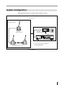
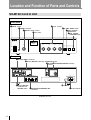
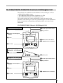
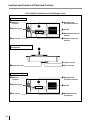
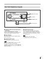
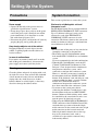
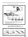
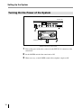
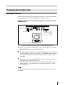
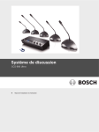
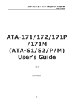
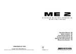
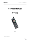
3-759-749-14 (1)
Conference System
Model:
SX-M100 Control Unit
SX-C100A/SX-C150 Chairman’s Unit
SX-D100A/SX-D150 Delegate’s Unit
SX-T100 Telephone Coupler
Operating Instructions
Before operating the unit, please read this manual thoroughly
and retain it for future reference.
© 1994 by Sony Corporation
Owner’s Record
The model and serial numbers are located on the rear of
the SX-M100 and on the bottom of the SX-C100A/
D100A/T100. Record the serial numbers in the spaces
provided below. Refer to them whenever you call upon
your Sony dealer regarding these products.
Model No. SX-M100
Model No. SX-C100A/C150
Model No. SX-D100A/D150
Model No. SX-T100
Serial No.______________
Serial No.______________
Serial No.______________
Serial No.______________
WARNING
To prevent fire or shock hazard, do not
expose the unit to rain or moisture.
For the customers in the U.S.A.
communications. Operation of this equipment in a
residential area is likely to cause harmful interference in
which case the user will be required to correct the
interference at his own expense.
You are cautioned that any changes or modifications not
expressly approved in this manual could void your
authority to operate this equipment.
The shielded interface cable recommended in this
manual must be used with this equipment in order to
comply with the limits for a digital device pursuant to
Subpart B of Part 15 of FCC Rules.
For the customers in Canada
This Class A digital apparatus complies with Canadian
ICES-003.
Pour les utilisateurs au Canada
Cet appareil numérique de la classe A est conforme à la
norme NMB-003 du Canada.
NOTICE FOR THE CUSTOMERS IN
THE UNITED KINGDOM
WARNING
THIS APPARATUS MUST BE EARTHED
This symbol is intended to alert the
user to the presence of uninsulated
"dangerous voltage" within the
product's enclosure that may be of
sufficient magnitude to constitute a risk
of electric shock to persons.
This symbol is intended to alert the
user to the presence of important
operating and maintenance (servicing)
instructions in the literature
accompanying the appliance.
WARNING
This equipment has been tested and found to comply
with the limits for a Class A digital device, pursuant to
Part 15 of the FCC Rules. These limits are designed to
provide reasonable protection against harmful
interference when the equipment is operated in a
commercial environment. This equipment generates,
uses, and can radiate radio frequency energy and, if not
installed and used in accordance with the instruction
manual, may cause harmful interference to radio
2
IMPORTANT
The wires in this mains lead are coloured in accordance
with the following code:
Green-and-yellow: Earth
Blue:
Neutral
Brown:
Live
As the colours of the wires in the mains lead of this
apparatus may not correspond with the coloured
markings identifying the terminals in your plug proceed
as follows:
The wire which is coloured green-and-yellow must be
connected to the terminal in the plug which is marked by
the letter E or by the safety earth symbol Yor coloured
green or green-and-yellow.
The wire which is coloured blue must be connected to
the terminal which is marked with the letter N or coloured
black.
The wire which is coloured brown must be connected to
the terminal which is marked with the letter L or coloured
red.
VORSICHT
Um Feuergefahr und die Gefahr eines elektrischen
Schlages zu vermeiden, darf das Gerät weder Regen
noch Feuchtigkeit ausgesetzt werden.
Für Kunden in Deutschland
Dieses Produkt kann im kommerziellen und in
begrenztem Maße auch im Industriellen Bereich
eingesetzt werden. Dies ist eine Einrichtung, welche die
Funk-Entstörung nach Klasse B besitzt.
Table of Contents
Outline .......................................................................................................... 4
Features .................................................................................................... 4
System Configuration .............................................................................. 5
Location and Function of Parts and Controls .......................................... 6
SX-M100 Control Unit ............................................................................ 6
SX-C100A/C150/SX-D100A/D150 Chairman’s Unit/Delegate’s Unit .. 9
SX-T100 Telephone Coupler ................................................................. 13
Setting Up the System ............................................................................... 14
Precautions ............................................................................................. 14
System Connection ................................................................................ 14
Turning On the Power of the System ..................................................... 16
Preparing the Control Unit ..................................................................... 17
Operation During a Conference .............................................................. 19
Operation Performed by the Chairman and Delegates .......................... 19
Taking Part in a Conference via a Telephone ........................................ 20
Troubleshooting Guide ............................................................................. 21
Specifications ............................................................................................. 22
3
Outline
Features
The SX-M100 conference system is a flexible discussion system that can be
configured with the versatile units introduced below.
The standard system supports a conference of up to 60 delegates. Connecting the
SX-E120 Expansion Unit (not supplied) allows the system to support up to 120
delegates. The SX-T100 Telephone Coupler (not supplied) allows the use of a
telephone line during a conference. By using the telephone, a person not actually in
the conference hall can also take part in the conference.
The standard system consists of the following units.
• SX-M100 Control Unit
This unit controls the conference system.
The control unit can be mounted in a 19-inch rack.
• Chairman’s Unit/Delegate’s Unit
– SX-C100A/SX-D100A Chairman’s Unit/Delegate’s Unit: Desktop
type. You can move these units freely in the conference room.
– SX-C150/SX-D150 Chairman’s Unit/Delegate’s Unit: Desk-mounted type.
These units are fixed to the desks.
These units feature both a microphone and speaker.
Use the above combination of the chairman’s unit and delegate’s unit.
• SX-T100 Telephone Coupler
This coupler is used to connect the control unit to a telephone line. Using this
coupler allows a person to take part in a conference from a remote location, even
from overseas.
In addition to the units described above, the following optional units are available.
SXA-120 Expansion Board
The board is designed to allow the expansion of the system’s functions. Installing
this board in the control unit allows the following function expansion units to be
connected.
• SX-E120 Expansion Unit
• SX-8300/SX-S100 Microphone Control Panel
Used to enable or disable delegates’ microphones.
When multiple SX-8300 microphone control panels are used, the power interface
unit is required.
When the SX-S100 microphone control panels are used, they are connected using
only the connecting cables.
For detailed information on the power interface unit, contact your Sony dealer.
• Personal computer
For details of the SXA-120 Expansion Board, refer to the manual supplied with the
expansion board.
4
System Configuration
The figure below shows an example of the conference system.
Conference hall
Conference seats
Operator section
SX-C100A
Chairman’s Unit a)
SX-T100
Telephone Coupler
SX-M100 Control Unit
ORIGINAL
VU
MONITOR
MIC/LINE 1
POWER
I
MIC/LINE 2
D/C UNIT MIC
D/C UNIT SP
MONITOR
4
ON
5
4
6
3
5
4
6
3
7
5
4
6
3
7
5
4
6
3
7
5
MIC/LIMIT
ON/OFF
6
3
7
DIRECT ACCESS
ON/OFF
SEAT ASIGN
START/END
7
PHONES
8
2
O
SX-D100A Delegate’s Unit a)
OFF
9
1
MIN
MAX
8
2
9
1
0
10
8
2
9
1
0
10
8
2
9
1
0
10
8
2
9
1
0
10
a) You can also use other combination of
the SX-C150/SX-D150.
System configuration
5
Location and Function of Parts and Controls
SX-M100 Control Unit
Front panel
1POWER
5Volume
switch
controls
6MIC
2PHONES connector
3MONITOR volume control
4Level meter
LIMIT ON/OFF button
7DIRECT
ACCESS
ON/OFF button
8SEAT
ASSIGN
START/END button
ORIGINAL
VU
MONITOR
MIC/LINE 1
POWER
I
D/C UNIT MIC
MIC/LINE 2
D/C UNIT SP
MONITOR
5
4
ON
4
6
3
7
5
4
6
3
5
3
7
4
6
5
3
7
4
6
5
MIC/LIMIT
ON/OFF
6
3
7
DIRECT ACCESS
ON/OFF
SEAT ASIGN
START/END
7
PHONES
8
2
O
2
9
1
OFF
MIN
8
9
1
MAX
0
10
8
2
9
1
0
8
2
9
1
10
0
10
8
2
9
1
0
10
Rear panel
9EXT UNIT IN/OUT connectors
0EXT IN-1 MIC/LINE connectors and MIC/LINE switch
!¡LINE OUT !™TELEPHONE COUPLER connector
connector
EXT UNIT
OUT
LINE OUT
EXT IN-1
IN
1
EXT IN-2
MIC
MIC
@TELEPHONE COUPLER
MIC
LINE
LINE
LINE
MIC
2
LINE
AC IN
DELEGATE'S/CHAIRMAN'S UNIT
4
3
2
1
!£EXT IN-2 MIC/LINE
connectors and
MIC/LINE switch
!∞y terminal
!¢DELEGATE’S/CHAIRMAN’S UNIT
connectors
SX-M100 Control Unit
6
!§AC IN connector
1 POWER switch
Setting the switch to ON (1 ) turns the power on.
The level meter will light.
Setting the switch to OFF (o) turns the power off.
2 PHONES connector (stereo phone jack)
Connect 8-ohm stereo or monaural headphones.
Note that the output is monaural even when stereo
headphones are connected.
3 MONITOR volume control
Adjusts the volume of the headphones.
4 Level meter
Indicates the level of the audio signal output to the
LINE OUT !¡, TELEPHONE COUPLER !™ and
DELEGATE’S/CHAIRMAN’S UNIT !¢
connectors.
5 Volume controls
Used to adjust the level of the following sound.
D/C UNIT SP volume control: Adjusts the level
of the audio signal output to the chairman’s
unit/delegate’s unit.
D/C UNIT MIC volume control: Adjusts the
input level of the audio signal sent from the
microphones on the chairman’s units and
delegate’s units.
MIC/LINE 1 volume control: Adjusts the input
level of the signal input through the EXT IN-1
MIC or LINE connector.
MIC/LINE 2 volume control: Adjusts the input
level of the signal input through the EXT IN-2
MIC or LINE connector.
When the MIC/LINE switch of the EXT IN-1 or
EXT IN-2 connector is set to LINE, the input level
of the signal input through the LINE connector can
be adjusted.
When the MIC/LINE switch of the EXT IN-1 or
EXT IN-2 connector is set to MIC, the input level
of the signal input through the MIC connector can
be adjusted.
6 MIC (microphone mode) LIMIT ON/OFF
button
Selects the microphone mode for the delegate’s
units.
The microphone of the chairman’s unit remains
live regardless of the setting of this button.
MIC (microphone) LIMIT ON: Press this button
to set the microphone to the speaker’s number
limitation mode. The button indicator lights.
Setting this mode allows the microphones of up
to five delegate’s units to be live at the same
time.
MIC (microphone) LIMIT OFF: Press the button
again to set the microphone to the speaker’s
number unlimitation mode. The button
indicator goes out. Setting this mode allows the
microphones of all delegate’s units to be live at
the same time.
7 DIRECT ACCESS ON/OFF button
This button is effective only when the SXA-120
Expansion Board (not supplied) is installed and the
SX-8300/SX-S100 Microphone Control Panel is
connected to the control unit.
While the SX-8300 is not connected, this button
indicator lights, even though it is not operative.
The button indicator does not go out even if you
press this button.
8 SEAT ASSIGN START/END button
This button is effective only when the SXA-120
Expansion Board (not supplied) is installed and the
SX-8300/SX-S100 Microphone Control Panel is
connected to the control unit for performing seat
assignment.
While the SX-8300 Microphone Control Panel is
not connected, the button indicator does not light
even if you press the button.
For details of the functions and how to use the DIRECT
ACCESS ON/OFF and SEAT ASSIGN START/END
buttons, refer to the manuals supplied with the SXA-120
Expansion Board.
9 EXT UNIT IN/OUT (external unit input/
output) connectors (phone jack)
Connect to the howling suppressor unit or filter
unit (not supplied).
Notes
• Be sure to connect both the IN and OUT
connectors. Connecting only one of the two
connectors results in incorrect operation of the
unit.
• When it is not necessary to use the howling
suppressor or filter unit, disconnect cables from
both connectors.
7
Location and Function of Parts and Controls
0 EXT IN-1 MIC/LINE (external 1 microphone/
line signal input) connectors and MIC/LINE
switch
EXT IN-1 MIC/LINE connectors
Accept an external audio signal.
MIC connector (XLR type): Connect a rostrum
or conference hall microphone.
Note
When you use a connecting cable with an XLR
connector, pin No.1 and the case (metal part) of
which are connected, noise may be picked up.
LINE connector (phono jack): Connect to
external equipment such as audio equipment.
MIC/LINE switch
Selects the signal input to the EXT IN-1 connector.
MIC: Set the switch to this position when a
microphone is connected.
LINE: Set the switch to this position when an item
of audio equipment is connected.
! ¡LINE OUT (line output) connectors
(phono jacks)
Supply the signal from the chairman’s unit/
delegate’s unit, that from the rostrum or conference
hall microphone. There are two connectors. Use
these connectors when recording the output to a
tape recorder or when sending the line output to
the monitor system transmitter by means of an
infrared or induction-based system.
!™ TELEPHONE COUPLER connector (6-pin
multi-connector)
Connect to the SX-T100 telephone coupler (not
supplied).
!£ EXT IN-2 MIC/LINE (external 2 microphone/
line signal input) connectors and MIC/
LINE (microphone/line signal select)
switch
EXT IN-2 MIC/LINE connectors
Input an external audio signal.
MIC connector (phone jack): Connect a rostrum
or conference hall microphone.
LINE connector (phono jack): Connect to
external equipment such as audio equipment.
MIC/LINE switch
Selects the signal input to the EXT IN-2 connector.
MIC: Set the switch to this position when a
microphone is connected.
LINE: Set the switch to this position when an item
of audio equipment is connected.
8
!¢ DELEGATE’S/CHAIRMAN’S UNIT
connectors (20-pin multi-connectors)
Connect to the SX-C100A/SX-C150/SX-D100A/
SX-D150 Chairman’s Unit/Delegate’s Unit. The
same signal is output from four connectors. Up to
15 SX-C100A/D100A units can be connected to
each of the four connectors. Thus, up to 60 SXC100A/SX-C150/SX-D100A/SX-D150 units can
be connected.
!∞ y (signal ground) terminal
Ground if necessary.
!§AC IN (AC power input) connector
Connect the unit to an AC power source by means
of the supplied AC power cord.
SX-C100A/C150/SX-D100A/D150 Chairman’s Unit/Delegate’s Unit
The following two combinations of the chairman’s unit and delegate’s unit are
available for use with the system.
• SX-C100A/SX-D100A Chairman’s Unit/Delegate’s Unit
• SX-C150/SX-D150 Chairman’s Unit/Delegate’s Unit
This section explains the location and function of parts and controls of the
chairman’s unit and delegate’s unit. The explanation applies to both combinations.
Read the explanation corresponding to the numbered parts and controls in the
illustration.
SX-C100A/SX-D100A Chairman’s Unit/Delegate’s Unit
Chairman’unit front panel
1Output connector
2Microphone
5Cable
with 20-pin multi-connector
6Voting
connector
and microphone
indicator
3Speaker
7PRIORITY
button and indicator
8MIC ON/OFF button and indicator
PRIORITY
4VOL
control
MIC ON/OFF
VOL 4
Chairman’s unit/
delegate’s unit side panel
9REC
OUT connector
!ºEarphone
Delegate’s unit front panel
1Output
5Cable
jacks
with 20-pin multi-connector
connector
6Voting
2Microphone
connector
and microphone
indicator
3Speaker
8MIC
ON/OFF button and indicator
MIC ON/OFF
4VOL
control
VOL 4
9
Location and Function of Parts and Controls
SX-C150/SX-D150 Chairman’s Unit/Delegate’s Unit
Chairman’unit top
2 Microphone and
9 REC OUT
connector
microphone indicator
†
! ºEarphone jacks
PRIORITY MIC ON/OFF
3 Speaker
8 MIC ON/OFF button and
indicator
4 VOL control
7 PRIORITY button and
indicator
Chairman’unit/delegate’s
unit bottom
6 Voting connector
1 Output connector
5 Input connector
Delegate’s unit top
2 Microphone and
9 REC OUT
connector
microphone indicator
†
! ºEarphone jacks
4 VOL control
MIC ON/OFF
3 Speaker
8 MIC ON/OFF button
and indicator
10
The explanations given here apply to both units,
unless noted otherwise, with the exception of
PRIORITY button 7.
1 Output connector
For SX-C100A/SX-D100A (20-pin multiconnector)
Connect the cable with a 20-pin multi-connector of
the chairman’s unit/delegate’s unit placed opposite
the SX-M100 Control Unit and the next
chairman’s unit/delegate’s unit.
For SX-C150/SX-D150 (D-sub 15-pin)
Connect to the input connector on the next
chairman’s unit and delegate’s unit.
2 Microphone and microphone indicator
The microphone can be rotated freely. The
microphone operation depends on the setting of the
MIC ON/OFF button 8.
For details, see the explanation of the MIC ON/OFF
button 8.
3 Speaker
The sound is heard through this speaker when the
microphone is not being used and when an
earphone is not plugged into the earphone jack.
The speaker’s volume is adjusted from the
SX-M100 Control Unit. To prevent howling,
nothing is output from the speaker when the
microphone of the chairman’s/delegate’s unit is
enabled. Also at the same time, the speaker volume
of the units on either sides of the unit is
automatically reduced.
4 VOL (volume) control
Adjusts the volume of the earphone. Even if the
VOLUME control is turned fully
counterclockwise, the earphone volume cannot be
turned off. (The speaker volume is not affected by
this control.)
5 Cable with 20-pin multi-connector (for
the SX-D100A/SX-C100A only)
Connect to the DELEGATE’S/CHAIRMAN’S
UNIT connector of the SX-M100 Control Unit,
SX-E120 Expansion Board (not supplied) or the
output connector of another chairman’s unit/
delegate’s unit.
5 Input connector (D-sub 15-pin) (for SXC150/SX-D150 only)
Connect to the DELEGATE’S/CHAIRMAN’S
UNIT connector of the SX-M100 Control Unit,
SX-E120 Expansion Board (not supplied) or the
output connector of another chairman’s unit/
delegate’s unit.
6 Voting connector
Connect to the SX-CV10/SX-DV10 voting unit
(not supplied).
For details, contact your Sony dealer.
7 PRIORITY button and indicator (for the
SX-C100A/SX-C150 only)
Press this button to disconnect the microphones of
the delegate’s units and enable the use of only the
microphone of the chairman’s unit.
Holding down this button turns on the microphone
of the chairman’s unit.
8 MIC ON/OFF button and indicator
SX-C100A/SX-C150: Pressing this button turns
the microphone on. The MIC ON/OFF button
indicator and microphone indicator 2light.
Pressing this button again turns the microphone
off. The indicators go out.
SX-D100A/SX-D150: When the MIC LIMIT ON/
OFF button on the control unit is set to OFF
(the MIC LIMIT ON/OFF button indicator does
not light), pressing this button turns the
microphone on. The MIC ON/OFF button
indicator and microphone indicator 2light. In
this mode, since the number of speakers is not
limited, the microphones of all the delegate’s
units are enabled.
When the MIC LIMIT ON/OFF button on the
control unit is set to ON (the MIC LIMIT ON/
OFF button indicator is lit), the number of
speakers is limited. Thus, when the MIC ON/
OFF buttons of more than six delegate’s units
are pressed at the same time, the indicator of
the sixth delegate’s unit blinks (for about 3
seconds) to tell the user that the microphone
cannot be enabled since the number of units
whose MIC ON/OFF button is pressed exceeds
six.
11
Location and Function of Parts and Controls
When the MIC ON/OFF button of the
delegate’s unit is pressed under the condition
where the PRIORITY button of the chairman’s
unit is held down, the MIC ON/OFF button
indicator and microphone indicator blink for
about 3 seconds to tell the user that the
microphone cannot be enabled.
9 REC OUT (recording output) connector
(minijack)
Connect to the input connector of the tape recorder
to record the monitor sound.
Note
Use a connecting cable with a terminating resistor
(RK-G64 and so on) to connect the unit to the
microphone input connector of a tape recorder.
Use a connecting cable without a terminating
register (RK-G69 and so on) to connect the unit to
the line input connector of a tape recorder.
! ºEarphone jacks (minijack)
Connect an earphone to monitor the signal from
the interpreter’s unit or the original signal.
12
SX-T100 Telephone Coupler
1CONTROL
2Power
UNIT connector
indicator
3POWER
ON/OFF switch
Movable part A
4Handset-securing
tape
SX-T100 Telephone Coupler
1 CONTROL UNIT connector (6-pin multiconnector)
Connect to the TELEPHONE COUPLER
connector of the SX-M100 Control Unit, using the
connecting cord supplied with the SX-T100.
2 Power indicator
This indicator lights when the telephone coupler
power is turned on.
4 Handset-securing tape
After being connected to other party telephone,
place your handset on the telephone coupler and
secure it with the handset-securing tape. Adjust the
movable part A in the above illustration, to fit the
handset being used.
Note
If the handset is not secured firmly,
communication may not be satisfactory.
3 POWER ON/OFF switch
Turns the telephone coupler power on or off .
Note
When the POWER ON/OFF switch is set to ON,
howling or noise may arise because the
microphone and the speaker are enabled. When the
telephone coupler is not used, set the POWER ON/
OFF switch to OFF.
13
Setting Up the System
Precautions
Safety precautions
This section explains how to connect the system.
Power supply
• Operate the unit only with a power source as
specified in “Specifications” section.
• Do not drop or place heavy objects on the power
cord. If the power cord is damaged, turn off the
power immediately. It is dangerous to use the
unit with a damaged power cord.
• Disconnect the power cord from the AC outlet by
grasping the plug, not by pulling the cord.
Chairman’s unit/delegate’s unit and
interpreter’s unit
The SX-M100 Control Unit is provided with four
DELEGATE’S/CHAIRMAN’S UNIT connectors.
Up to 15 chairman’s/delegate’s units can be
connected to each of the DELEGATE’S/
CHAIRMAN’S UNIT connectors in serial
connection. The distance between the control unit
and the last chairman’s/delegate’s unit should not
exceed 60 meters (196.8 feet).
Keep foreign objects out of the cabinet
Dropping flammable or metal objects into the
cabinet, or spilling liquids onto the cabinet can
lead to accidents.
In case of malfunctions
If you notice any unusual sound, smell or smoke,
turn off the power immediately, disconnect the
power supply and contact your Sony dealer.
Cleaning
Clean the cabinet and panels by wiping with a soft,
dry cloth. For severe stains, moisten the cloth with
a small amount of neutral solvent, and finish by
wiping with a dry cloth. Do not use alcohol,
benzine, thinner or volatile liquids, as these may
discolor or damage the cabinet surface.
14
System Connection
Notes
• Be sure to turn off the power of any units before
attempting connection or disconnection.
• The desktop type SX-C100A/D100A and the
desk-mounted SX-C150/D150 are used with this
system.
It is not recommended to mix both combinations.
• When the SX-C100A/D100A is used, the SXC700A/C750/D700A/D750 Chairman’s Unit/
Delegate’s Unit, designed for the simultaneous
interpretation conference system, can be
connected to configure this conference system.
However, after the system power is turned on,
the microphone indicator and MIC ON/OFF
buttons of the chairman’s unit and delegate’s unit
continue to blink for about 3 seconds to inform
that the SX-C700A/D700A units for
simultaneous interpretation conference system
have been connected to the conference system.
• If you turn on the system power before
connecting the chairman’s unit/delegate’s unit,
the microphone indicators and MIC ON/OFF
buttons continue to blink and these units cannot
be controlled by the control unit. In such a case,
turn the power off, then back on again.
• When using the DELEGATE’S/CHAIRMAN’S
UNIT connectors of the SX-M100 Control Unit,
attach the dust caps removed from the 20-pin
multi-connectors on the control unit to the 20-pin
multi-connectors on the last unit connected.
If the 20-pin multi-connector has no dust cap,
keep it away from metal tools, such as
screwdrivers to prevent the connector being
inadvertently shorted.
The figure below shows an connection example.
Other party
Telephone line
SX-T100
CONTROL UNIT
Connecting cord
(supplied with SX-T100)
TELEPHONE COUPLER
LINE OUT
EXT IN-1
EXT UNIT
OUT
IN
MIC
@TELEPHONE COUPLER
MIC
1
EXT IN-2
MIC
LINE
LINE
LINE
MIC
2
LINE
AC IN
DELEGATE'S/CHAIRMAN'S UNIT
4
3
2
AC IN
1
to AC power source
DELEGATE’S/CHAIRMAN’S UNIT a)
Cable with 20-pin
multi-connector b)
AC power cord
(supplied with SX-M100)
to output
connector a)
SX-C100A c)
SX-D100A c) (Up to 15 units of SX-C100A and
SX-D100A can be connected to one line.)
a) For details of connecting cables, see “How to connect cables” shown below.
b) You can extend the distance between units by using the RK-1710/1713 connecting cable (not supplied).
c) The desk-mounted SX-C150/SX-D150 can also be used in this system. Up to 15 desk-mounted SXC150 and SX-D150 units can be connected to one line.
The specially designed cables are used to connect these units to the system.
For details, contact your Sony dealer.
System connection example
How to connect cables of the SX-C100A/SX-D100A
The figure below shows how to connect and disconnect the 20-pin multiconnectors of the chairman’s/delegate’s unit and RK-1710/1713 connecting
cables.
When connecting
When disconnecting
When disconnecting
White mark
White mark
With the white mark on the 20-pin
multi-connector facing up, push the
connector home until it clicks.
When connecting
Grasp the knurled part of the
connector and pull it towards
you.
Meet the white marks on each
connector and push the
connectors each other until they
click.
Grasp the knurled part
of the connector and
pull it towards you.
15
Setting Up the System
Turning On the Power of the System
Control unit
ORIGINAL
VU
MONITOR
MIC/LINE 1
POWER
I
MIC/LINE 2
D/C UNIT MIC
D/C UNIT SP
MONITOR
4
ON
5
4
6
3
5
3
7
4
6
5
3
7
4
6
5
4
6
3
7
7
5
MIC/LIMIT
ON/OFF
6
3
7
1
9
DIRECT ACCESS
ON/OFF
SEAT ASIGN
START/END
PHONES
8
2
O
OFF
9
1
MIN
MAX
8
2
9
1
0
10
8
2
9
1
0
10
8
2
9
1
0
8
2
10
0
10
2
Telephone coupler
3
Turning on the power of the system
16
1
Turn on the power of the units connected to the EXT IN-1/2 connectors of the
control unit.
2
3
Set the POWER switch of the control unit to ON.
When necessary, set the POWER switch of the telephone coupler to ON.
Preparing the Control Unit
Adjusting the audio level
Adjust the audio signal output to the chairman’s/delegate’s unit and input from the
external equipment connected to EXT IN-1/2 before the conference.
Adjusting the output level of the audio signal to the chairman’s unit/
delegate’s unit
ORIGINAL
VU
Level meter
MIC/LINE 1
MONITOR
POWER
I
MIC/LINE 2
D/C UNIT MIC
D/C UNIT SP
MONITOR
4
ON
5
4
6
3
5
4
6
3
7
5
4
6
3
7
5
4
6
3
7
7
5
MIC/LIMIT
ON/OFF
6
3
7
1
9
DIRECT ACCESS
ON/OFF
SEAT ASIGN
START/END
PHONES
8
2
O
OFF
9
1
MIN
8
2
9
1
MAX
0
10
8
2
9
1
0
10
8
2
9
1
0
10
8
2
0
Control unit
10
3
2
MIC ON/OFF
VOL 4
1
Chairman’s unit/delegate’s unit
Output level adjustment of the audio signal to the chairman’s unit/delegate’s unit
1
Select several chairman’s units/delegate’s units placed in the hall and set their
MIC ON/OFF buttons to turn on their indicators.
2
Adjust the speaker volume on the chairman’s units/delegate’s units so that the
level meter indicates around 0 VU using the D/C UNIT MIC volume control on
the control unit, while an assistant in the conference hall is speaking into the
microphone.
3
If howling occurs, rotate the D/C UNIT SP volume control counterclockwise to
reduce the volume until the howling stops.
If howling does not stop even if you rotate the D/C UNIT SP volume control
counterclockwise, it is recommended to use the howling suppressor or filter
unit (not supplied).
Note
The person speaking into the microphone should bring his/her mouth close to the
microphone.
17
Setting Up the System
Adjusting the input level of the audio signal from equipment
connected to EXT IN-1/2 connectors
1
Rear of the control unit
EXT UNIT
OUT
LINE OUT
EXT IN-1
MIC
IN
1
EXT IN-2
MIC
MIC
@TELEPHONE COUPLER
LINE
LINE
LINE
MIC
2
LINE
AC IN
DELEGATE'S/CHAIRMAN'S UNIT
4
3
2
1
Level meter
ORIGINAL
VU
MONITOR
MIC/LINE 1
POWER
I
MIC/LINE 2
D/C UNIT MIC
D/C UNIT SP
MONITOR
4
ON
5
4
6
3
7
5
4
6
3
5
3
7
4
6
5
4
6
3
7
5
MIC/LIMIT
ON/OFF
6
3
7
DIRECT ACCESS
ON/OFF
SEAT ASIGN
START/END
7
PHONES
8
2
O
OFF
9
1
MIN
MAX
8
2
9
1
0
8
2
9
1
10
0
10
8
2
9
1
0
10
8
2
9
1
0
10
Front of the control unit
2
Input level adjustment of the audio signal from external equipment
1
• To adjust the output of the conference microphone, set the MIC/LINE switch
of the EXT IN connector, to which the conference microphone to be adjusted
is connected, to MIC.
• To adjust the output of external equipment, set the MIC/LINE switch of the
EXT IN connector, to which the external equipment to be adjusted is
connected, to LINE.
2
Adjust either MIC/LINE 1 or MIC/LINE 2, corresponding to the equipment to
be adjusted, so that the level meter pointer indicates about 0 VU.
Note
In this case, do not rotate the MASTER control because it has already been
adjusted as described in “Adjusting the output level of the audio signal to the
chairman’s unit/delegate’s unit” (previous page).
To select the microphone mode of the chairman’s unit/delegate’s units
Select the microphone mode (whether the number of speakers is limited) according
to the conference type.
To limit the number of speakers to five: Press the MIC LIMIT ON/OFF button
such that the button indicator lights.
Note
When the power of the control unit is turned off, the MIC LIMIT ON/OFF button
is automatically reset to OFF even if it has been set to ON.
To set the mode to limit the number of speakers to five after the power of the
control unit is turned on again, press the MIC LIMIT ON/OFF button such that the
button indicator lights.
To allow all speakers to participate freely: Press the MIC LIMIT ON/OFF
button such that the button indicator goes out.
18
Operation During a Conference
Operations Performed by the Chairman and Delegates
Operations common to both the chairman and delegates
The chairman and delegates can both talk and listen by using their individual unit.
The operations are the same.
To speak
Press the MIC ON/OFF button of the unit.
The button indicator and the microphone indicator light. The microphone is
enabled.
When the MIC ON/OFF button indicator and microphone indicator blink
(delegate’s unit)
The microphone mode is set such that only five person can speak at any one time.
Currently, the microphones of five units are already turned on. In this case, the
indicators blink for about 3 seconds, then go out.
The MIC ON/OFF button indicator and microphone indicator blink for about 3
seconds, then go out, when the PRIORITY button of the chairman’unit is held
down.
Note
When a delegate’s microphone is enabled, the volume level of his or her earphone
is automatically reduced. When a delegate is listening through the speaker, the
speaker is turned off and the volume levels of the speakers of the units on both
sides of the unit are also automatically reduced while the microphone is enabled.
Upon finishing speaking
Upon finishing speaking, press the MIC ON/OFF button again.
The MIC ON/OFF button indicator and the microphone indicator go out and the
microphone is disabled.
To listen the sound through the earphone
The sound can be monitored through the earphone. Connecting an earphone to the
earphone jack mutes the speaker of the unit.
Set the CH selector to the channel corresponding to the desired target language.
Note
The speaker volume is controlled from the control unit. It cannot be adjusted from
each chairman’s unit/delegate’s unit.
Chairman’s operations
The chairman can interrupt a delegate and take control of the conference at any
time.
To take control of the conference
Press and hold down the PRIORITY button. While the PRIORITY button is held
down, the PRIORITY button and the microphone indicator are lit and the
microphone of the chairman’s unit is enabled. On the other hand, the microphones
of the delegates’ units are disabled.
19
Operation During a Conference
Taking Part in a Conference via a Telephone
A person can take part in a conference from a remote location by using the
SX-T100 Telephone Coupler .
1
Telephone coupler
3
Taking part in a conference via the telephone
1
2
Set the POWER ON/OFF switch of the telephone coupler to ON.
3
Place the handset on the telephone coupler after the other party answers the
phone. The handset catch part is movable. Adjust the coupler to the handset
size and secure the handset with the handset-securing tape.
The called person can now take part in the conference.
Set up a telephone connection with the party who will take part in the
conference.
Notes
• Orient the handset correctly.
• If the handset is not adjusted to the coupler, the satisfactory communication may
not be possible.
20
Troubleshooting Guide
Should a problem arise in your system, check the system while referring to the
instructions in the table below. If the system continues to malfunction after
applying the following checks and remedies, contact your nearest Sony dealer.
The system indicates the problem by lighting the microphone indicator and MIC
ON/OFF button of chairman’s/delegate’s units.
Lighting of the
microphone indicator
and MIC ON/OFF button
of the chairman’s unit/
delegate’s unit
The indicator and button
blink for a few seconds
when the POWER
switch of the control unit
is set to ON.
The indicator and button
of the chairman’s/
delegate’s units
continue to blink, after
the power switch of the
control unit is set to ON.
Possible cause
Remedies
The chairman’s unit/
delegate’s units for a
conference system, SXC100A/D100A/SX-C150/
D150, and those for a
simultaneous
interpretation conference
system, SX-C700A/
D700A/SX-C750/D750,
have been connected.
The units whose indicator
and button are blinking
cannot be controlled by
the control unit and cannot
be used in this system.
The SX-C700A/D700A/SX-C750/D750 can be used.
However, same sound is output from channel 1 to channel 6.
After the unit has been
operated for a while
after the power is turned
on, the unit’s indicator
and button start blinking
and do not go out, even
after a few seconds.
A communication error
has occurred.
The volume of the
earphone cannot be
adjusted by using the
VOL control.
The indicator and button
blink and the
microphone is disabled
even if the MIC ON/OFF
button is pressed.
The earphone may be
disconnected.
• The mode is that where
the number of speakers
is limited.
• The PRIORITY button is
held down by the
chairman.
• When the indicator and button of units subsequent to the
16th unit of the units connected to one DELEGATE’S/
CHAIRMAN’S connector of the control unit blink:
– More than 16 units cannot be connected to one
DELEGATE’S/CHAIRMAN’S connector in series.
Disconnect the 16th unit and subsequent units.
• Even though the number of connected units is less than 16,
the indicators of some of the connected units blink:
– The first unit whose indicator and button are blinking may
be defective, or the connecting cable may be broken.
Disconnect the first unit of those whose indicator and
button are blinking. When the indicator and button of the
subsequent units stop blinking and go out, it indicates
that the disconnected unit was defective. Remove it from
the system or replace it with a functioning unit.
When the indicator and button continue to blink even
after removing the first unit, the connecting cable is
probably broken. Replace the connecting cable linking
the first unit whose indicator and button are blinking and
the unit immediately prior to that unit.
• Even though the number of connected units is less than 16,
the indicator and button of some of the connected units
blink:
– The unit whose indicator and button blink is defective.
Disconnect it from the system or replace it with a
functioning unit.
Briefly turn the power off, then back on again.
If the unit subsequently operates normally, communication is
resumed.
If this problem occurs frequently, contact your nearest Sony
dealer.
If the indicator and button continue to blink just after the
power is turned on again, a problem described above may
have occurred. Proceed as described above.
Insert the earphone plug into the earphone jack surely.
• Wait until the speaker finishes speaking. Press the MIC
ON/OFF button again.
• Wait until the chairman releases the PRIORITY button.
21
Specifications
SX-M100 Control Unit
Input/output connectors
DELEGATE’S /CHAIRMAN’S
UNIT (20-pin multi-connector) ×4
TELEPHONE COUPLER (6-pin
multi connector ) ×1
Input
EXT IN-1/EXT IN-2
MIC (XLR 3-pin connector) ×1
Balanced type, input level 0.77
mV (–60dBs), for microphone
having low impedance
MIC (phone jack) ×1
Unbalanced type, input level
0.77 mV (–60dBs), for
microphone having low
impedance
LINE (phono jack) ×2
Balanced type, input level 250
mV (–10dBs), input impedance
10 kilohms
AC IN (3-pin) ×1
for AC power input
Output
LINE OUT (phono jack) ×2
Output level 250 mV (–10dBs),
load impedance 10 kilohms or
more
PHONES (stereo phone jack) ×1
Power requirements
USA model:120 V, 60Hz
European model: 230 V, 50/60Hz
Power consumption
USA model: 1.06A
European model: 90W
Dimensions
424 × 98 × 378 mm (w/h/d)
(16 3⁄4 × 3 7⁄8 × 15 inches)
Mass
6.2 kg (13 lb 10 oz)
Accessories supplied
AC power cord (1)
Operating instructions (1)
22
SX-C100A/SX-C150 Chairman’s Unit
SX-D100A/SX-D150 Delegate’s Unit
Output
Earphone output (minijack) ×2
REC OUT (minijack)×1
Output level 250 mV (–10dBs),
load impedance 47 kilohms
Power requirements
24 V (supplied with the 20-pin
multi-connector)
Power consumption
45 mA
Dimensions
SX-C100A/SX-D100A:
134 × 401 × 152 mm (w/h/d)
(6 3⁄4 × 15 7⁄8 × 6 inches)
SX-C150/SX-D150:
245 × 372.5a) × 100 mm (w/h/d)
(9 3⁄4 × 14 3⁄4 × 4 inches)
a) This does not include the part
under the desk.
The part under the desk is 40 mm.
Mass
SX-C100A/SX-D100A:
0.7 kg (1 lb 9 oz)
SX-C150/SX-D150:
0.65 kg (1 lb 7 oz)
SX-T100 Telephone Coupler
Input/output CONTROL UNIT (6-pin multi
connector) ×1
250 mV (–10 dBs)
Power consumption
18 mA
Dimensions
90 × 74.5 × 213 mm (w/h/d)
(3 5⁄8 × 3 × 8 1⁄2 inches)
Mass
0.6 kg (1 lb 5 oz)
Accessory supplied
Connecting cord (1)
Design and specifications are subject to change
without notice.
23
Sony Corporation
Printed in Japan