1
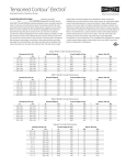
Table of Contents
1. IMPORTANT SAFETY INSTRUCTIONS ................................................................................. 4
2. COOKTOP MEASUREMENTS ............................................................................................... 5
3. POSITIONING THE COOKTOP AND LOCATION REQUIREMENTS .................................... 6
3.1 Gas supply requirements ................................................................................................................................ 8
3.2 Electrical requirements .................................................................................................................................... 9
4. INSTALLING THE COOKTOP ............................................................................................... 11
5. CHECKING OPERATION ...................................................................................................... 14
6. WIRING DIAGRAMS ............................................................................................................. 15
INSTRUCTIONS FOR THE INSTALLER: these are intended for the qualified engineer who is able to
install, commission and test the appliance
3
Important Safety Instruction
1. IMPORTANT SAFETY INSTRUCTIONS
READ AND SAVE THESE INSTRUCTIONS – Your Safety And the Safety of Others Are Very Important.
We have provided many important safety messages throughout this manual and on your appliance.
Read all instructions before using your appliance and always obey all safety messages.
RECOGNIZE SAFETY INFORMATION
This is a safety alert symbol. This symbol alerts you to potential hazards that can kill or hurt you and
others.
UNDERSTAND SIGNAL WORDS
A signal word – DANGER, WARNING, or CAUTION – is used with the safety-alert symbol. DANGER
identifies the most serious hazards. It means you can be killed or seriously injured if you do not
immediately follow instructions. WARNING means you can be killed or seriously injured if you do not
follow instructions. CAUTION indicates a potentially hazardous situation which, if not avoided, may
result in minor or moderate injury.
All safety messages will inform you as to potential hazards, inform you on how to reduce the risk of
injury and as to what can occur if the instructions are not followed.
IMPORTANT: Observe all government codes and ordinances.
WARNING: For your safety, the information in this manual must be followed to minimize the risk
of fire or explosion, or to prevent property damage, personal injury or death.
Do not store or use gasoline or other flammable vapors and liquids in the vicinity of this or any
other appliance.
WHAT TO DO IF YOU SMELL GAS
•
Do not attempt to switch on any appliances.
•
Do not touch any electrical switches.
•
Do not use any phones in your building.
•
Immediately call your gas supplier from a neighbor's phone. Follow the gas supplier's instructions.
•
lf you cannot reach your gas supplier, call the fire department.
•
Installation and service must be performed by a qualified installer, service agency or the gas
supplier.
NOTE: This cooktop is manufactured for use with Natural gas. To convert to LP/Propane gas, see
instructions in the Gas Conversion Kit provided in the literature package.
Proper gas supply connection must be available. See "Gas supply requirements”.
In the State of Massachussets, the following installation instructions apply:
- Installations and repairs must be performed by a qualified or licensed contractor, plumber, or gasfitter
qualified or licensed by the State of Massachusstets.
- If using a Ball valve, it shall be T-handle type.
- A flexible gas connector, when used, must not exceed 3 feet.
4
Instructions for the Installer
2. COOKTOP MEASUREMENTS
5
Instructions for the Installer
3. POSITIONING THE COOKTOP AND LOCATION REQUIREMENTS
NOTE: The following operation requires building and/or carpentry work and must therefore be carried
out by a competent technician.
Installation can be carried out on various material, such as masonry, metal, solid wood, plastic laminated
wood etc. As long as they are heat resistant (T = 90°C - 194° F).
Observe all governing codes and ordinances. Do not obstruct flow or combustion and ventilation air.
-
It is the installer’s responsibility to comply with installations guidelines specified on the model/serial
rating plate. The model/serial rating plate is located on the underside of the cooktop burner box.
-
The cooktop should be installed in a location away from strong draft areas, such as windows, doors
and strong heating vents or fans.
-
All openings in the wall or floor where cooktops is to be installed must be sealed.
-
Cabinet opening dimensions that are shown must be used. Given dimensions are minimum
clearances.
-
Grounded electrical supply is required. See “Electrical Requirements” section. Proper gas supply
connection must be available. See “Gas Supply Requirements” section
To prevent accidents or ruining the mobile components of the appliance, the following steps must be
taken before performing the procedures described below:
1 Remove all packaging parts (e.g. crate, carton, polystyrene and metal hooks). Do not eliminate this
manual as it is an integral part of the appliance and it should be kept handy for easy reference
whenever needed.
2 Temporarily remove all removable parts from the cooktop that could fall and cause personal injury or
damage to objects (burners, crowns and flame caps) during the attachment procedures These parts
must be refitted before using the appliance.
The measurements supplied in the tables referring to the figure below must be followed when attaching
the appliance to the support structure.
6
Instructions for the Installer
Cooktop
widht
MINIMUM DISTANCE
B
C
D
E
22” - 22 /16”
18 /8”- 19”
1
8 / 4”
3
3 /8”
7
1 /16”
13/16” - 1 /16”
23 5/8”
600 mm
560 - 570 mm
478 - 482 mm
210 mm
86 mm
36 mm
20 - 40 mm
600 mm
27 1/2”
22” - 22 7/16”
18 7/8”- 19”
8 1/ 4”
3 3/8”
1 7/16”
700 mm
560 - 570 mm
478 - 482 mm
210 mm
86 mm
36 mm
20 - 40 mm
700 mm
39 3/8”
33 11/16” - 33 7/8”
19 1/10” - 19 3/10”
8 1/ 4”
4 7/16”
1 7/16”
13/16” - 1 9/16”
39 3/8”
1000 mm
855 - 860 mm
485 - 490 mm
210 mm
112 mm
36 mm
20 - 40 mm
1000 mm
5
23 /8”
A
7
7
F
G
9
13
/16” - 1 9/16”
27 1/2”
Gas line opening
Wall: everywhere, 5” (12.7 cm) below underside of countertop.
Cabinet base: everywhere, within 6” (15.2 cm) from rear wall is recommended.
Grounded outlet
Locate within 24” (61 cm) from the right rear corner of the cut out drawer.
7
Instructions for the Installer
3.1 Gas supply requirements
EXPLOSION HAZARD
WARNING
-
Use a new AGA- or CSA-approved gas supply line.
-
Install a shut-off valve.
-
Securely tighten all gas connections.
-
lf connected to LP, have a qualified technician ensure that gas pressure
does not exceed a 14" water column.
-
Examples of qualified technicians include licensed heating personnel,
authorized gas company personnel, and authorized service personnel.
-
Failure to do so can result in death, explosion, or fire.
NOTE:
- observe all government codes and ordinances.
- The cooktop must be connected to a regular gas supply.
1)
This installation must conform to local codes and ordinances. In the absence of local codes, installations
must conform to American National Standards, National Fuel Gas Code ANSI Z223.1 - latest edition** or
CANI 13149.1 or 2**.
2)
If local codes permit, a flexible metal appliance connector with the new AGA- or CSAcertified design, 4-5
feet (1.2-1.5 m) long, 1/2" or 3/4" I.D., is recommended for connecting this cooktop to the gas supply line.
Do not bend or damage the flexible connector when moving the cooktop. The pressure regulator has 3/8
female pipe threads. You will need to determine the fittings required, depending on the size of your gas
supply line, the flexible metal connector and the shut-off valve.
The supply line shall be equipped with an approved shut-off valve.
This valve should be located in the same room as the cooktop and
should be in a location that allows for easy opening and closing.
Do not block access to the shut-off valve. The valve is necessary for
turning the gas to the appliance on or off.
3)
8
Instructions for the Installer
4)
The regulator must be checked at
a minimum water column of at
least 1” (2.5 cm) above the set
pressure. The inlet pressure to
the regulator should be as follows
for operation and monitoring of
the regulator setting:
- NATURAL GAS: Set pressure at
6” (15.2 cm). Supply pressure 714” (17.8 cm to 35.5 cm)
maximum
- LP GAS: Minimum pressure of
10” (25.4 cm). Supply pressure
14“ (35.5 cm).
5)
Line pressure testing: Testing above 112 PSI (3.5 kPa), with water column of 14” (35.6 cm) (gauge).
The cooktop and its individual shut-off valve must be disconnected from the gas supply piping system
during any pressure testing of that system at test pressures greater than 1/2 psig (3.5 kPa).
Testing below 112 PSI (3.5 kPa) with a water column of 14” (35.6 cm) (gauge) or lower.
The cooktop must be isolated from the gas supply piping system by closing the respective manual shutoff valve during any pressure testing of the gas supply piping system at test pressures equal to or less
than 1/2 psig (3.5 kPa).
If the appliance is installed on an oven, the gas pipe must not pass
along the back of the oven, as this may cause overheating.
6)
3.2 Electrical requirements
ELECTRICAL SHOCK HAZARD
WARNING
-
Plug into a grounded 3-prong outlet.
-
Do not remove ground prong.
-
Do not use an adapter.
-
Do not use an extension cord.
-
Failure to follow these instructions can result in death, fire, or electrical
shock.
-
lf codes permit and a separate ground wire is used, it is recommended that a qualified electrician
checks that the ground path is adequate.
-
Check with a qualified electrician if you are not sure whether the cooktop is properly grounded. Do
not ground to a gas pipe.
-
A 120-volt, 60-Hz, AC-only, 15-ampere, fused electrical supply is required. A time-delay fuse or circuit
breaker is recommended. It is recommended that a separate circuit serving only this appliance be
provided.
9
Instructions for the Installer
3.2.1 Recommended Grounding Method
For your personal safety, this cooktop must be grounded. This cooktop is equipped with a 3-prong
ground plug. To minimize possible shock hazard, the cord must be plugged into a mating 3-prong
ground-type outlet, grounded in accordance with the National ANSI/NFPA 70 Electrical Code (latest
edition*) or the Canadian Electrical Code (CSA)** and local codes and ordinances. lf a mating outlet is
not available, it is the personal responsibility and obligation of the customer to have a properly polarized
and grounded, 3-prong outlet installed by a qualified electrician.
Copies of the standards listed above may be obtained from:
* National Fire Protection Association One Batterymarch Park, Quincy, Massachusetts 02269
** CSA International 850,1 East Pleasant Valley Rd., Cleveland OH 44131-5575
10
Instructions for the Installer
4. INSTALLING THE COOKTOP
1)
Remove the upper polystyrene guard and the side guards.
2)
Remove the grids, the nylon sheet serving to protect the cooktop
during shipping and the burner crowns. These parts could make
product assembly more difficult.
Connection to the gas mains may be made with a flexible metal
pipe and conforming to the provisions defined by current standard
regulations in force. USE A SOAPY SOLUTION TO CHECK FOR
PROPER TIGHTNESS.
NEVER USE A FLAME.
3)
The following procedures must be performed to adjust the gas
supply pressure for LP operation of the cooktop:
1 Unscrew cap A on the pressure regulator
2 Turn it to the part where LP is printed
3 Re-tighten it and lock the pins in the slots provided.
4 There is an arrow printed on the back of the energy regulator.
The tip of the arrow indicates the end to be connected to the
cooktop connector.
4)
Carefully position the insulation gasket (supplied) on the external perimeter of the hole found on the top
surface (see figures below) and try to make it stick to the entire surface by applying light pressure with
your hands. Refer to the distances shown in the figure for the model to be installed, keeping in mind that
for both models the long front side has to skim the hole.
A
B
C
D
5/16”
2 11/16”
9/16”
2 15/16”
8 mm
68 mm
15 mm
75 mm
11
Instructions for the Installer
5)
Secure the cooktop to the counter with brackets A (supplied).
Carefully trim any excess from edge B on the gasket. The
distances in the following drawing refer to the hole on the inner
side of the gasket.
The diagram below shows the exact positions of the holes to be used for clamping the hob to the top by
the brackets correctly.
NOTE: Use all of the brackets supplied with the appliance to fasten it to the support structure.
6)
12
Use pipe-joint compound made for use with NATURAL and L.P.
gas. lf flexible metal connector is used, be certain tubing is not
kinked.
Instructions for the Installer
Always use pipe-joint compound made for use with NATURAL
GAS and L.P. GAS between pressure regulator D and adaptator C
and between pressure regulator D and pipe E. If flexible metal
conductor is used, be certain tubing is not kinked.
7)
Use only pipes (E) conforming to standard regulations in force,
inserting gasket B (supplied) between fitting A adaptator C.
The adaptor C must be fitted on the gas connection A before fixing
the hob.
Always place a suitable sealing medium (such as Teflon tape)
between pressure regulator D and adaptator C and between
pressure regulator D and pipe E.
8)
Plug power supply cord into grounded outlet.
13
Instructions for the Installer
5. CHECKING OPERATION
After having fastened the top to the support structure, some simple procedures are required to check for
proper operation.
1)
Check for any gas leaks in the vicinity of the cooktop connector, the pressure regulator and the safety
valve.
FIRE HAZARD
WARNING
-
Use a soapy solution to check for proper tightness.
-
Never test for gas leaks with a match or other flames.
-
Failure to follow this instruction can result in death or fire
NOTE: The regulator Is fitted with a checkpoint outlet gas pressure to check the exact pressure supplied
to the appliance.
Refit the crowns, flame caps and grids on the cooktop in the
following order:
1 Fit the crowns, ensuring that they are perfectly locked into their
housing on the cooktop.
2 Fit the flame caps on the crowns, ensuring that the edges
match perfectly.
2)
3 Fit the grids, making sure to fasten the side spokes in the
special “A” seats found on the cooktop.
These procedures must be repeated for each burner on the
cooktop.
CAUTION: refit all flame caps in the same points from which they were removed. In fact, the flame
cap positions cannot be changed. After refitting them, ensure that they are fitted perfectly and
that there is no clearance between the top and the flame caps.
The cooktop's electrical circuit can be checked for proper operation
only after top assembly has been completed as described in step
2) and you have checked to ensure that all parts have been fitted
properly:
1 a spark must light on all burners when the knobs on the top are
pressed
3)
2 when each knob on the cooktop is pressed and turned to the
min flame symbol ( ), the entire crown should light.
3 lf burners do not light properly, turn the control knob to the
"OFF" position . Check that burner caps and crowns are in
the proper position. Check that the power supply cord is
plugged in and that circuit breaker or house fuse has not blown.
Check that the shut-off valve is in the "ON" position. Check
operation again. lf a burner does not light at this point, contact
your dealer for assistance.
14
Instructions for the Installer
6. WIRING DIAGRAMS
The power cord on this appliance is equipped with a threee pronge polarized plug (grounding) which
mates with standard three pronged (grounding) wall receptacles.
WARNING
Label all wires prior to disconnection when servicing controls.
Wiring errors can cause improper and dangerous operation.
Verify proper operation after servicing.
15
Instructions for the Installer
The power cord on this appliance is equipped with a threee pronge polarized plug (grounding) which
mates with standard three pronged (grounding) wall receptacles.
WARNING
16
Label all wires prior to disconnection when servicing controls.
Wiring errors can cause improper and dangerous operation.
Verify proper operation after servicing.
Instructions for the Installer
The power cord on this appliance is equipped with a threee pronge polarized plug (grounding) which
mates with standard three pronged (grounding) wall receptacles.
WARNING
Label all wires prior to disconnection when servicing controls.
Wiring errors can cause improper and dangerous operation.
Verify proper operation after servicing.
17