1
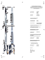
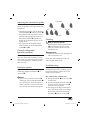
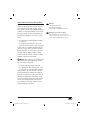
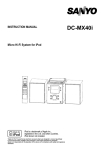
RADIO SET 6 KH 2130 Radio Set Operating instructions KOMPERNASS GMBH BURGSTRASSE 21 ⋅ D-44867 BOCHUM www.kompernass.com ID-Nr.: KH 2130-06/09-V3 CV_KH2130_DT35269_LB6.indd 1 01.09.2009 10:05:05 Uhr KH 2130 Konformitätserklärung gemäß dem Gesetz über Funkanlagen und Telekommunikationsendeinrichtungen (FTEG) und der Richtlinie 1999/5/EG (R&TTE) Declaration of Conformity in accordarice with the Radio and Telecommunications Terminal Equipment Act (FTEG) and Directive 1999/5/EC (R&TTE Directive) Hersteller / Verantwortliche Person Manufacturer / responsible person Kompernaß GmbH Burgstraße 21 44867 Bochum erklärt, dass das Produkt declares that the product Funkübertragungs-Set Radio Transmission Set Type (ggf. Anlagenkonfiguration mit Angabe der Module): KH 2130 Type (if applicable, configuration including the modules) Telekommunikations(Tk-)endeinrichtung Telecommunicätions ternlinal equiprrient 5 Funkanlage Radio equipment Verwendungszweck / lntended purpose Übertragung von Audio und Video Signalen Transmission of audio and video signals bei bestimmungsgemäßer Verwendung den grundlegenden Anforderungen des § 3 und den übrigen einschlägigen Bestimmungen des FTEG (Artikel 3 der R&TTE) entspricht. complies with the essential requirements of §3 and the other relevant provisions of the FTEG (Article 3 of the R&TTE Directive), when used for its intended purpose. Gesundheit und Sicherheit gemäß § 3 (1) 1. (Artikel 3 (1) a)) Health and safety requirements pursuant to § 3 (1) 1. (Article 3 (1) a)) angewendete harmonisierte Normen Harmonised Standards applied EN 60065: 2002 + A1: 2006 Schutzanforderungen in Bezug auf die elektromagnetische Verträglichkeit (§ 3 (1) 2, Artikel 3 (1) b) Protection requirements concerning electromagnetic compatibility § 3(1)(2), (Article 3(1) b)) angewendete harmonisierte Normen Harmonised Standards applied EN 301 489-1 V1.6.1 EN 301 489-3 V1.4.1 Maßnahmen zur effizienten Nutzung des Funkfrequenzspektrums Measures for the efficient use of the radio frequency spectrum 5 Luftschnittstelle bei Funkanlagen gemäß § 3(2) (Artikel 3(2) Air interface of the radio systems pursuant to § 3(2) (Article 3(2) Angewendete harmonisierte Normen Harmonised standards applied EN 300 220-3 V1.1.1 EN 300 440-2 V1.1.2 Bochum, 29.07.2009 Hans Kompernaß Geschäftsführer CV_KH2130_DT35269_LB6.indd 2 01.09.2009 10:05:19 Uhr CONTENT PAGE Intended Use 2 Contents 2 Technical data 3 Safety instructions 3 The device components 6 Putting the device into use 6 Connecting the transmitter 6 Connecting the receiver 8 Switching on 8 Improving the transmission quality 9 Channel configuration (parallel operation) 9 Expansion options 9 Cleaning 9 Troubleshooting 9 Disposal 10 Importer 10 Important warranty information 11 Read these operating instructions carefully before using the device for the first time and preserve this booklet for later reference. Pass this booklet on to whoever might acquire the device at a future date. -1- IB_KH2130_DT35269_LB6.indb 1 04.09.2009 13:11:46 Uhr Intended Use Contents The device inintended exclusively for private, non-commercial use. The radio transmission set is suitable for audio and video equipment, such as: 1 Radio transmission set (1 x transmitter, 1 x receiver) 2 Wall plug transformers (9 V /300 mA) 1 SCART—CINCH adapter IN 1 SCART—CINCH adapter OUT 2 CINCH—Jacks 3,5 mm cable, 3 core 1 CINCH—CINCH cable, 3 core 1 Infrared cable (infrared transmission diode cable for the remote control signals to be transmitted) 3 Adhesive pads for the infrared transmitter diodes 1 AUDIO adapter 3,5 mm stereo jack on CINCH sockets 1 Operating manual • • • • • Televisions SAT receiver/set top boxes DVD/CD players PCs etc. The equipment must have the appropriate AV inputs/outputs. The radio transmission set is intended for: • Wireless transmission of audio, video and infrared signals: (Transmission distances outdoors are possible up to approx. 100 metres!). No warranty is provided for damages resulting from improper use of the device! -2- IB_KH2130_DT35269_LB6.indb 2 04.09.2009 13:11:46 Uhr Technical data Safety instructions Power supply: Transmitter 9 V / 300 mA Receiver 9 V / 300 mA Manufacturer HON-KWANG ELECTRIC CO., LTD Model number: HKA-0930EC-230K Input: 230 V ~/ 50 Hz, 35 mA, 9 W Output : 9 V , 300mA 2,7 VA Protection class: II / • Please read the following information carefully. • The operating manual must be stored safely and passed on to any future owners of the radio transmission set. • Only use the product for the intended purpose as described in this operating manual. Risk of electric shocks! • Set up the radio transmission set outside of the reach of children. Never allow children to play with the radio transmission set without supervision. Children could attempt to insert foreign objects into the openings in the device housing. • Only connect the devices to a socket with a mains voltage of 230 V ~ /50 Hz using the supplied mains adapters. • Only plug the mains power adapter (wall plug transformer) in the designated 9 V connection socket of the respective device. • Protect the device from moisture. Use it only in dry rooms, do not use it outdoors or close to liquids. • Make sure that neither the device nor the mains adapter becomes wet or damp or sustains any other damage during use. • When a storm and/or thunderstorm with the risk of lightening threatens, disconnect the mains adapter from the mains power. • Never allow any fluids to enter into the housings of the radio transmission sets. • Never submerse the device in water. Wipe it only with a slightly damp cloth. Transmitter connections: • 9 V Supply voltage • 2 x Audio/Video IN (jacks 3,5 mm) • 1 x TV output (jack 3,5 mm) • Infrared socket (IR) Receiver connections: • 9 V Supply voltage • Audio R/L and Video OUT (CINCH) Operating temperature: Humidity: +5 ~ +35°C 5 ~ 90 % (no condensation) Dimensions: Transmitter/Receiver unit: 135 x 55 x 145 mm Weight : • Receiver approx. 170 g • Transmitter approx. 185 g • Mains power adapter approx. 202 g Video signal: 1 Vss Audio signal: 1 Vss (type) Transmission power: 10 mW Open space range: up to 100 m Within enclosed buildings or other locations, transmission disruptions (reflections) may arise that strongly impair the image and sound quality. -3- IB_KH2130_DT35269_LB6.indb 3 04.09.2009 13:11:46 Uhr • Do not operate the device if a mains adapter, the adapter's power cable or the device itself is damaged. Arrange for a defective mains adapter to be repaired or replaced as soon as possible by Customer Services. • You are not permitted to open the housing of the radio transmission set or to modify it in any way. Otherwise, the warranty becomes void. adapter can cause a fire or electric shock. Check the mains adapter from time to time. Should it become damaged, contact your nearest authorised customer service centre or your dealer to have it replaced. Risk of fire! • Avoid plugging in the wall plug transformer immediately after moving the radio transmission set from a cold environment to a warm one. The temperature change could result in condensation that could damage the radio transmission set. Once the radio transmission set has reached room temperature, it can be safely put into operation. • Do not place any open fire sources, such as candles, directly next to or on the device. • Do not place any objects filled with liquid (e.g. vases) on the device. • The wall plug transformer must not be covered because it becomes very warm during operation. Notice regarding power disconnection: • To completely disconnect the device from mains power, the mains adapter must be unplugged from the wall socket. For this reason, the device must be used in a location where unobstructed access to the power socket is always assured so that you are able to immediately pull out the power plug in the event of an emergency. To eliminate the risk of fire, prevent unintended activation and save energy costs, the mains adapter must be unplugged from the wall socket when the device is not in use. • Always grasp the mains adapter directly when you wish to unplug it. Do not pull on the cable and never touch the mains adapter with wet hands, this could result in a short circuit or you receiving an electric shock. Do not place furniture or other objects on the cable of the mains adapter, and ensure that it cannot become trapped. Never make a knot in the power cable and do not bind it together with other cables. Run the mains adapter cable as well as any CINCH or infrared cable so that no one will step on it or trip over it. A damaged mains Risk of suffocation! • Do not leave packaging material lying unattended. Plastic foils and bags and pieces of styropor etc. are not toys, they can be dangerous for small children. -4- IB_KH2130_DT35269_LB6.indb 4 04.09.2009 13:11:46 Uhr Danger from radio signals! • Do not operate the device in a hospital, a hospital operations room or in the vicinity of medical electronic systems. The transmitted radio waves could impair the function of sensitive devices. Keep the device at least 20 cm away from pacemakers since the proper functioning of the pacemaker could be impaired by radio waves. The transmitted radio waves can cause interference noises in audio equipment. Do not bring the device into the vicinity of flammable gases or an explosive environment (e.g. paint shop) while the radio components are switched on since the transmitted radio waves could trigger an explosion or a fire. The range of the radio waves depends on ambient and environmental conditions. Risk of accidents and injury! • This device is not intended for use by individuals (including children) with restricted physical, physiological or intellectual abilities or deficiences in experience and/or knowledge unless they are supervised by a person responsible for their safety or receive from this person instruction in how the device is to be used. Children must be supervised to ensure that they do not play with the device. Damage to the device • Do not expose the radio transmission set to high temperatures, direct sunlight, severe vibrations or high mechanical loads. • Do not use any aggressive chemical substances for cleaning. -5- IB_KH2130_DT35269_LB6.indb 5 04.09.2009 13:11:46 Uhr The device components Putting the device into use First take all device components from the packaging and remove all packing foil and tape. Fig. A: The transmitter: q Transmitter w LED status indicator e Switch ROOM 1 r Switch ROOM 2 t Infrared connection socket (IR) y Output for a TV u AV input 2 i AV input 1 o Connection socket a Transmitter's on/off switch s Transmitter channel toggle switch (on the underside of the device) Important notice: Even when the system (transmitter + receiver) is switched off, the manufacturer still recommends disconnecting the wall plug transformer from the mains power or using a power strip with a shut-off switch. Only in this way is complete switch off assured thus contributing to economical consumer attitude. Connecting the transmitter Fig. B: The receiver: d Receiver f Infrared receiver g LED operating indicator h Audio/Video CINCH outputs j Connection socket for the supply voltage k Receiver's on/off switch l Reception channel switch (bottom of device) 1( Wall plug transformer (2 pieces) 2) CINCH—3,5mm jacks cables (2 pieces) 2! SCART—CINCH adapter "IN" 2@ SCART—CINCH adapter "OUT" 2# Infrared cable with 3 transmit diodes 2$ AUDIO adapter 3.5 mm mini-stereo to CINCH female 2% CINCH—CINCH cable Note: You can connect two signal sources. The signal to be transmitted can be selected via a switch on the front panel of the transmitter. Thereby the radio transmission set can transmit the image and sound signals of every device that emits a sound and/or video signal via a suitable connection: • DVD Player / CD Player • VCR • Television • SAT receiver/set top box • Video camera • Computer video card, etc. Connecting signal sources to the transmitter: • On devices with cinch outputs for the audio and video signals you connect these via one of the supplied CINCH— 3,5mm jack cables 2) to the socket "AV IN 1" i on the rear panel of the transmitter q. -6- IB_KH2130_DT35269_LB6.indb 6 04.09.2009 13:11:46 Uhr • For this you connect the supplied infrared cable 2# to the transmitter's infrared connection socket t. • Remove the protective foil from one of the supplied adhesive pads and attach the pad to the rounded off side of one of the infrared cable's 2# transmission diodes. • Now remove the 2 protective foils from the adhesive pad and attach the transmission diode to the infrared receiver of your signal source. Note: Observe the colour coding: > The white CINCH plug carries the left audio channel signal and belongs in the white CINCH socket. > The red CINCH plug carries the right audio channel signal and belongs in the red CINCH socket. > The yellow CINCH plug carries the video signal and belongs in the yellow CINCH socket. • If required you can connect a second device as well, with the transmitter and for this select the socket "AV IN 2" u. • If the signal source of your signal is available via a SCART connection, you can use the supplied SCART— CINCH adapter "OUT" 2@ between the device and the CINCH—3,5mm jack cable 2). • The A/V output of your signal source is now occupied. If you, nevertheless, want to connect the signal source to a TV, connect the TV via the socket "OUTPUT TO TV" y to the transmitter q. For this you can use either one of the supplied CINCH—3,5mm jack cables 2) or, if both are already occupied, an equivalent cable from your local dealer. Note: Avoid attaching the full length of the transmission diode to the infrared receiver of the signal source. Otherwise it is possible that direct remote control commands will no longer be received. • Proceed in the same manner to connect further signal sources and/or other devices that you want to control with the radio transmission set. • Insert the cable plug of one of the supplied wall plug transformers 1( into the connection socket for the supply voltage o. • Insert the wall plug transformer 1( into a properly connected 230 V~/ 50 Hz mains power socket. Infrared connection Using a computer as the signal source You can control the signal source via the remote control even if you are not in the same room. The receiver d picks up the signal and sends it back to the transmitter q which then redirects the signal via the infrared cable 2# to the signal source. You can also transmit the video signal of a computer if the computer's video card has a VIDEO output available. -7- IB_KH2130_DT35269_LB6.indb 7 04.09.2009 13:11:46 Uhr Switching on For the sound transmissions use, if necessary, the AUDIO adapter 3,5 mm jack on CINCH sockets 2$, which you connect to the output of the sound card if this has no cinch output. The yellow plug of the CINCH—3,5mm jack cable 2) you connect to the video card's video output. • Move the ON/OFF switch a and k of the transmitter and receiver to the "ON" position to switch them both on. • Switch the signal source on and, if necessary, start playback. • Switch the TV (target device) on and activate the A/V inputs to which you have connected the receiver. • Select on the transmitter and on the receiver, via the CHANNEL switch s and l, implicitly in each case the same transmission channel. The radio transmission should now function. Tips: The video card must have an FBAS output available. Make sure that the computer is correctly configured for outputting video on the video card. Note: The data/signals sent from the transmitter are not encrypted. This means that compatible devices within the reception range are capable of eavesdropping on the signal. The radio transmission set uses an "open standard". Connecting the receiver • Connect the Audio/Video CINCH outputs h of the receiver d to the A/V inputs on the target device, probably a television set. For this you use the supplied three core CINCH cable 2%. If necessary, with the aid of the supplied SCART—CINCH adapter "IN" 2!. • To switch the signal source AV 1 and/ or 2 for a TV connected to the transmitter q press the button "ROOM 1" e (= the room in which the transmitter is located). • To switch the signal source AV 1 and/ or 2 for a TV connected to the receiver d press the button "ROOM 2" r (= the room in which the receiver is located). • Point the remote control of the signal source to the infrared receiver f of the receiver d. The commands are sent to your signal source. Note: Be sure to match the colours correctly. • Insert the cable plug of the second supplied wall plug transformer 1( into the connection socket for the supply voltage j. • Insert the wall plug transformer 1( into a properly connected 230 V~/ 50 Hz mains power socket. Important! Try, if required, to operate the receiver d in various locations to avoid cancellation effects and interference and thus improve the transmission quality. -8- IB_KH2130_DT35269_LB6.indb 8 04.09.2009 13:11:46 Uhr Improving the transmission quality Transmitter You can try the following measures to improve the quality in event of transmission disruptions: • Change the position and/or direction of the transmitter q and/or receiver d. • For problems with the remote control signal quality change the position of the infrared cable's 2# transmission diodes to the infrared receiver of the signal source. • Try setting one of the other 4 transmission channels via the CHANNEL switch s and l. Receiver Cleaning Risk of electric shock! Disconnect the wall plug transformer (1() from the mains power socket when you want to clean the radio transmission set. Channel configuration (parallel operation) Important! Chemical cleansers may damage the radio transmission set. You can operate up to 4 radio transmission sets within close proximity of each other. Then you select, for each set, their own channel from the 4 different available channels. Clean the radio transmission set only with a slightly damp cloth. Troubleshooting Expansion options If a problem arises, please check the following table first. If the problem cannot be resolved please contact one of the listed service locations. Expand the radio transmission set by connecting multiple transmitters q or receivers d. No audio/video transmission > Are the transmitter q and receiver d switched on? > Are the transmitter channel switch s and the receiver channel switch l set to the same channel? > The range of the radio transmission set is reduced by walls and ceilings. Reduce the distance between the transmitter q and the receiver d. Note: If you want to control a receiver d selectively with several transmitters q you should never have several transmitters switched on at the same time. This prevents transmission disruptions. -9- IB_KH2130_DT35269_LB6.indb 9 04.09.2009 13:11:47 Uhr > Check the CINCH and AV connections on the connected devices as well as on the transmitter q and the receiver d. > If you are using other radio devices (same frequency), this may result in disruptions. It may also affect the range of the radio transmission set. > The signal source must be switched on (i.e. DVD player) and playback started. Poor transmission quality > Change the direction of the transmitter q and the receiver d. > Change the channel setting s/l on both components. Make sure that the transmitter q and the receiver d have the same setting. > If you are using other radio devices (same frequency), this may result in disruptions. It may also affect the range of the radio transmission set. Disruptions in remote control commands > Point your remote control directly at the infrared receiver f. Otherwise the commands cannot be executed. > Fasten the infrared transmission diodes of the infrared cable 2# slightly offset to the infrared receiver of the signal source. > If you are using other radio devices (same frequency), this may result in disruptions. It may also affect the range of the radio transmission set. Disposal Do not dispose of the device in your normal domestic waste. This product is subject to the provisions of European Directive 2002/96/EC. • Arrange for the product, or parts of it, to be disposed of by a professional disposal company or by your communal waste facility. • Observe the currently applicable regulations. In case of doubt, please contact your waste disposal centre. Dispose of packaging materials in an environmentally responsible manner. Importer KOMPERNASS GMBH BURGSTRASSE 21 44867 BOCHUM, GERMANY www.kompernass.com - 10 - IB_KH2130_DT35269_LB6.indb 10 04.09.2009 13:11:47 Uhr Important warranty information DES Ltd Tel.: 0870/787-6177 Fax: 0870/787-6168 e-mail: [email protected] You receive a 3-year warranty for this device as of the purchase date. Should you, in spite of our high quality standards, have grounds for complaint please contact our Service Hotline. In the event that processing of your complaint is not possible by telephone, here you will receive Kompernass Service Ireland Tel.: 1850 930 412 (0,082 EUR/Min.) Standard call rates apply. Mobile operators may vary. e-mail: [email protected] • a processing number (RMA number) as well as • an address to which you can send your device for repair under warranty. In the case of a mail-in shipment please enclose a copy of the purchase receipt (sales slip). The device must be securely packed and the RMA number clearly visible. Products sent in without an RMA number cannot be processed. Note: The warranty provisions cover only material or manufacturing defects. The warranty is not valid; • to parts subject to wear and tear • for damage to breakable parts, such as switches or rechargeable batteries. This product is for private use only and is not intended for commercial applications. The warranty is void in the case of abusive and improper handling, use of force and internal tampering not carried out by our authorized service branch. Your statutory warranty claims are not restricted by this warranty. - 11 - IB_KH2130_DT35269_LB6.indb 11 04.09.2009 13:11:47 Uhr - 12 - IB_KH2130_DT35269_LB6.indb 12 04.09.2009 13:11:47 Uhr