1
Foriii
1 141
w
1
Re. 2ol)
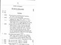
SINGER
SERVICE MANUAL
Class 269w
I
SINGLE NEEDLE
LOCK STITCH
THE SINGER MANUFACTURING COMPAN
Y
Copyright () 1963 by The Singer Manufacturin
g Company
Copyright Under International Copyright Union
All Rniht Reserved under Inter-American Copyri
ght Union
*A Trodernc,lr ci THE SINGER MANUFACT
URING COMPANY
Printed in U. 5. A.
TABLE OF CONTENTS
DESCRIPTION OF MACI-f INES
OPERATION
ADJUSTMENT
11
12-79
80-841
INSTRUCTIONS FOR ORDERING
PARTS LIST
NUMERICAL LIST
3
3-6
6-10
.
.
iNDEX
—
Accessories
Adjusting Device
Arch Clamp
Arm Shaft
End Play Removal
Barring
Buttonholes
Pockets
Bell Crank
Belt Guard
Belt Loop Tacking
Bell Tension
Bobbin
Removal
Winding
Bobbin Case
Removal
Replacement
Threading
Bobbin Thread Tension
Bobbie Winder,...,,,
.ents
A
Bow Fas..ning
Brake Installation
Brake Lining Care
Button Clamp
Button Sewers
Cam
Timing
Clamp Lifting Mechanism
Cleaning
Clearance under Clamp
Covers
Description of Machines
Driving Arm
Adjustment
End Play Removal (Arm Shaft)
Engaging Arm
Adjustment
Fastening ows
Feed Cam See Cam)
Feed Plate Carrier Bar
Feed Plate Positioning
Flat Bed Work Plate
Gauge 239369
interlocking Arm
Knife Bar
Knife Holder
Knife Thread Holder
Knives
Adjustment
Lateral Rock Shaft
Length of Tack Adjustment
Lifting Arm
58-79
36
12, 40-44, 52, 56
14
8
3
42, 52
46, 50
8, 22, 52
18, 58
3, 56
9
24
4
5
24
4
5
5
6
32
5, 6
3, 42
10
10
34
3, 36-38
3, 38-52,56
8
3, 22
4
3
18, 36
3
20
7
8
28
9
3, 42
,
12, 36, 40, 56
7
3, 54, 79
6, 7
26
16
42
38
18, 42
8
20, 36
7
6
Line Tack
Link Arm Adjustment
Longitudinal Rock Shaft
Lubrication and Cleaning
Machine Pulley
Driving Accessories
Pulley (loose), Packing
hine
Mac
Needle
Setting
Sizes
Needle Bar
Height Setting
Stroke
Needle Bar Crank
Needle Thread Tension,
Oiling
Oscillating Shafts
Recoil Absorbing Mechanism
Sewing Straps
Shoe Tacking
Size of Needles
Shuttle
Timing
Shuttle Driver Adjustment
Space behind Needle
Speed
Split Feet
Starting Lever
Adjustments
Stop Motion, Broke
Installation
Stop Motion Timing
Tacking Adjustments
Tacking Belt Loops
Tension
Regulation
Tension Position Guide
Adjustment
Thread Cutter on Face Plate
Thread Guide
Threading
Thread Retainers
Thread Wiper
Throat Plate
Tripping Mechanism Adjustment
Tripping Points
Timing
Twist of Thread
Uneven Winding, Correction for
“V” Belt Tension Adjustment
Vertical Drive Shaft
Width of Tack Adjustment
20,
3,
74,
3, 4, 36,
48,
3
7
36
4
14
76
4
40,
6G
4
22
6
3
14
6
4
16
9, 26
3, 44
3, 40, 48
4
24, 36
7
/
3
3
44
26
9
26
10
10
7
3, 56
28
6
22, 23
6
3, 18
5, 28
5
5, 28, 36, 42
22, 36, 44,52, 56
.
.
18, 36, 40, 42
8
3, 38.50
10
5
9
7
.3
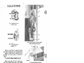
DESCRIPTION OF MACHINES
Machine 269w8 is designed for barring pockets on
clothing and general barring and tacking opera
tions.
Single needle, lock stitch.
Needle, Catalog 1628 (68x5).
Link take-up. Short bealc, central bobbin, ad
justable oscillating shuttle.
Manually operated thread cutter.
Automatic stop and clutching device.
Two-piece machine pulley (tight) and (loose);
“V” belt groove 2-1/4 inches outside diameter.
Needle bar stroke, 1-9/16 inches.
Clearance under clamp, 5/8 inch.
Space behind needle, 8 inches.
Bor pattern 1/8 to 5/8 inch long and 1/16 to
5/’32 inch wide; consists of 42 stitches (12 stay
ing, 27 covering and 3 tying stitches).
Cylinder bed. Flat bed type work plate fur
nished on request.
Other varieties of Machines of Class 269w are
similar to Machine 269w8, with the following ex
CptionS
-
Machine 269w12 for barring pockets and for other
bar tacking operations.
Bar pattern 1/8 to 5/8 inch long and 1/16 to
5/32 inch wide; consists of 36 stitches (12 staying,
21 covering and 3 tying stitches).
Needle, Catalog 1628 (68x5).
-
Machine 269w14 for tacking shoes.
Tack pattern 1/8 to 5/8 inch long; consists of
21 stitches including 5 overlapping stitches.
Needle, Catalog 3072 (16x100).
.
Machine 269w17 similar to Machine 269w5, ex
cept for cam which produces a tack consisting of
16 stitches (6 parallel, 1 cross-over, 6 parallel and
3 tying stitches).
Needle, Catalog 1627 (68x3).
-
Machine 269w26 for barring pockets on clothing
and other general barring and tacking operations.
Bar pattern 1/8 to 5/8 inch long and 1/16 to
5/32 inch wide; consisting of 28 stitches (8 staying,
17 covering and 3 tying stitches).
Needle, Catalog 1628 (68x5).
-
Machine 269w38 for barring buttonholes in clothing.
Bar pattern 1/8 to 1/4 inch long and 1/16 to
5/32 inch wide; consists of 21 stitches (7 staying,
11 covering and 3 tying stitches).
Regularly fitted with flat bed type work plate
and a clamp for contracting the cut edges of the
buttonholes.
Clearance under clamp, 13/32 inch.
Space behind needle, 7-3/4 inches.
Needle, Catalog 1628 (68x5).
-
Machine 269w5
for stitching 2 or 4 hole buttons
with 21 stitches (18 cross and 3 tying stitches).
Regularly fitted with button clamp for 14 to 50
ligne buttons. If specified on order, machine will
be fitted with clamp for 14 to 50 ligne thin buttons.
Space behind needle, 7 inches.
Needle, Catalog 1627 (68x3).
-
Machine 269w7 for tacking shoes. Tack pattern
1/8 to 3/8 inch long, with 18 stitches (no tying
stitches).
Needle, Catalog 3072 (16x100).
-
Machine 269w9 for barring buttonholes, fastening
bows and other ornaments on shoes and garments.
Bar pattern 1/8 to 5/16 inch long; consists of
21 stitches (7 staying, 11 covering and 3 tying
stitches).
Needle, Catalog 1628 (68x5).
Machine 269w39 for tacking belt loops on trousers,
slacks, sportswear, shirts, etc.
Line tack 1/8 to 1/2 inch long; consists of 28
stitches (including 3 tying stitches).
Regularly fitted with flat bed type work plate.
Needle, Catalog 1628 (68x5).
-
-
Machine 269w11 for general barring and for sew
ing straps on underwear, etc.
Bar pattern 3/8 to 7/8 inch long and 1/16 to
/32 inch wide; consists of 42 stitches (7 staying,
.2 covering and 3 tying stitches).
Needle, Catalog 1628 (68x5).
-
SPEED
The maximum speed recommended for all ma
chines of this Class (except the button sewers) is
2000 R. P. M.
Button sewing Machines 269w5 and 269w17 are
designed to run at a maximum speed of 1850 R.P.M.
The maximum efficient speed for any particular
machine is determined by the material being sewn,
the thread used and the operation performed.
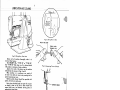
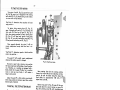
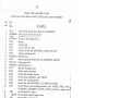
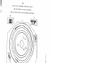
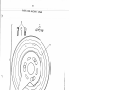
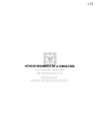
LUBRICATION AND CLEANING
,—
Fig. 3. Oiling Point in Rear
Fig. 2. Oiling Parts, Front View
Clean and oil machine thoroughly when it is
received from factory.
Use SINGERk OIL, “TYPE B” or “TYPE D”.
Use ‘‘TYPE D” OIL when an oil is desired which
will produce a minimum of stain on fabrics.
Apply oil at each of the places on the machine
indicated by the arrows in Figs. 2 and 3.
When machine is in continuous use, apply oil
at least twice daily to insure easy running and to
prevent unnecessary wear.
Machine pulley (loose) should be repacked with
grease, at least once each year.
Using short bristled brush (not point of scissors
or shears), clean out all lint or other waste from
around hook area, and between moving parts on
underside of throat plate.
Close all covers after oiling and cleaning. Wipe
off excess oil from surfaces of machine that may
come in contact with material.
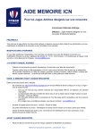
NEEDLES
Use SINGER* needles
Catalog 1627 (68x3), for Machines 269w5
and 269w17.
Catalog 3072 (16x100), for Machines 269w7
and 269w14.
Catalog 1628 (68x5), for all other varieties
of Class 269w Machines.
Size of needle is determined by weight of thread
and type of material being sewn.
-
-
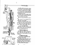
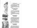
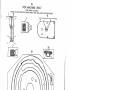
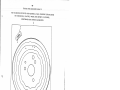
Fig. 4. Determining Twist of Thread
LOOSEN SCREW
LONG
INSERT NEEDLE UP
AS FAR AS POSSIBLE
AND TIGHTEN SCREW
-
THREAD
Use only left twist thread in needle. Either
right or left twist thread can be used in bobbin.
To determine twist, hold thread as shown in
Fig. 4. Then twirl thread over toward you if strands
of thread tighten, thread is left twist; if strands
unwind, thread is right twist.
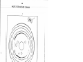
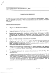
TO SET THE NEEDLE
Set the needle, as instructed in Fig. 5.
Long groove of needle should face operator,
with eye of needle directly in line with cylinder
bed of machine.
-
Fig. 5. Setting the Needle
RELEASE
LATCH
BOBBIN
2. HOLD LATCH AND
PULL CASE FROM SHUTTLE
DROPS
OUT
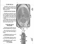
Fig. 6.
Removing Bobbin Case
Fig. 7. Removing Bobbi9
TO REMOVE THE BOBBIN
Remove bobbin case and bobbin as instructe.
in Figs. 6 and 7.
.:
5
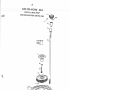
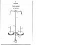
TO WIND THE BOBBIN
Place bobbin on bobbin winder spindle, as shown
in Fig. 8 and push it up closely against shoulder,
having small pin in shoulder enter slot in bobbin.
Pass the thread from the unwinder through the
threading parts shown in Fig. 8. Wind thread clock.
wise around bobbin a few times.
Push bobbin winder lever to bring bobbin winder
pulley in firm contact with machine driving belt.
See page 6 for adiustment of this contact.
Bobbins can be wound, while machine is stitch
ing.
Bobbin winder will stop automatically when
sufficient thread is wound on bobbin.
If thread does not wind evenly on bobbin, loosen
thread guide screw A, Fig. 8 on tension control at
top of machine and move thread guide forward or
back, as required. Securely retighten screw A.
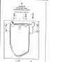
TO THREAD BOBBIN CASE
Hold bobbin so that thread will unwind on top
from left to right as shown in Fig. 9 and thread
bobbin case as instructed in Figs. 9 toll.
TO REPLACE BOBBIN CASE
Replace bobbin case in shuttle, as instructed in
Fig. 12, making certain that position finger on
bobbin case slips into notch provided for it at top
of shuttle race.
TO THREAD THE MACHINE
Fig. 8. Winding the Bobbin
1. PULL THREAD
INTO SLOT
Pass needle thread from unwinder through thread.
ing points shown in Figs. 13 and 14.
Note: Threading for upper thread retainer used
only on Machines 269w5, 269w9 and 269w17 in place
of thread eyelet, as shown in inset at top of Fig. 13.
Lower thread retainer, shown in Fig. 13, does not
exist on Machines 269w5, 269w9 and 269w17.
UPPER
THREAD RETAINER
FOR 269W5, 269W9
AND 269W17 ONLY
2. DRAW THREAD DOWN
AND UNDER SPRING
4. HOLDING LATCH,
REPLACE BOBBIN CASE
ON STUD’
Fig. 10.
3. TURN BOBBIN CASE
OVER AND DRAW
THREAD UP INTO
POSITION
FINGER
Fig. 11.
5. RELEASE LATCH
PRESS BACK UNTIL LATCH
CATCHES GROOVE IN STUD
Fig. 12.
LOWER THREAD RETAINER
ON ALL MACHINES EXCEPT
269W5, 269W9 AND 269W17
Fig. 13. Threading
the Machine
Draw about two inches of
thread through eye of needle
with which to start sewing.
Fig. 14. Threading
the Needle
()
TO REGULATE THE T[NSIONS
-
_.c
MORE TENSION
B
LESS
I
TENSION
g. 15. RegLilciti nq i
on Needle Thread
a
Si Oil
MORE TENSION
LESS TENSION
—F
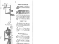
Fig. 17. Adjusting Contact of Bobbin Winder
Pulley with Machine Driving Belt.
Fig. 16. Regulating Tension
on Bobbin Thread
T2
2732
Tension on needle thread is regulated by thumb
nut in front of tension discs, as instructed in Fig.15.
Tension on bobbin thread is regulated by screw
on bobbin case tension spring, as instructed in
Fig. 16.
TO ADJUST BOBBIN WINDER PULLEY
Bobbin winder pulley B, Fig. 17 should press
firmly upon machine driving belt C when winding
bobbin. (See instructions on page 5.) To adjust,
engage bobbin winder for winding operation and,
with links D and E in locked position, loosen screw
F. Move pulley, as required and securely retighten
screw F.
7Q4
Fig. 18. Checking Needle Bar Height
(Using Gauge 239369)
TO SET THE NEEDLE BAR
AT THE CORRECT HEIGHT
Turn machine pulley until needle bar
down to its lowest point. With needle bar
positian, needle bar depth-hole K, Fig. 18
be about 27/32 inch above the top surface
throat plate, as shown in Fig. 18.
moves
in this
should
of the
To adjust, loosen needle bar clamping screw
Fig. 19 and move needle bar up or down in connec
tion stud P, as required. Securely retighten screw M.
TO ADJUST THE TENSION POSITION GUIDE
Remove arm side cover plate and loosen pinch
screw G (see inset, Fig. 19) on lifting arm H. Re
move face plate. Raise presser bar until first radius
of tension position guide S2, Fig. 19 touches ten
sion pin. Tighten lifting arm pinch screw G.
E26B7
Fig. 19. Setting Needle Bar at Correct Heighi
7
TO TIME THE SHUTTLE
Turn machine pulley until needle bar moves
down to its lowest point. Loosen pinch screw 350606
in shuttle driver. (See pages 24 and 25).
Insert gauge as shown in Fig. 20, bring shuttle
point against gauge. Then, tighten socket screw in
shuttle driver.
--*
TO ADJUST SHUTTLE DRIVER AND
NEEDLE GUARD
To adjust shuttle in relation to needle, loosen
set screw T2, Fig. 18, and, using two screwdrivers
as wedges, move shuttle race bushing to desired
position. Tighten screw T2.
To adjust needle guard, loosen screw U2, Fig. 21
and move needle guard in or out as required. Tighten
screw U2.
Fig. 20. Timing the Shuttle
(Using Gauge 239369)
TO ADJUST WIDTH OF TACK
(ALONG THE BED)
a
I
F-
1
[
r
Needle Guard Adjustment
.
4
Fig. 22. Adjusting Width of Tack
and Positioning Feed Plate
Ear5eE
S
Fig. 23. Adjusting Length of Tack
To adjust width of tack, loosen nut Q, Fig. 22
(reached through back opening in base of machine).
To make a wider tack (along the bed), slide the nut
over to the right. To make a narrower tack, slide the
nut over to the left. Tighten screw Q.
After adjusting width of tack, it may be neces
sary to adlust position of feed plate in relation to
needle. Loosen socket screw R, Fig. 22 and move
feed plate central with needle. Tighten socket
screw R.
ADJUST LENGTH OF TACK
(ACROSS THE BED)
Remove the cover plate from the base of the
machine, as shown in Fig. 23. Through the opening,
loosen nut S, Fig. 23. To make a longer tack (across
the bed), slide nut S over to right. To make a shorter
tack, slide nut S over to left. Tighten nut S.
After adjusting length of tack, it may be neces
sary to adjust position of feed plate in relation to
needle. Loosen socket pinch screws T, Fig. 22
and V2, Fig. 24 and set feed plate central with
needle. Set driving arm and link arm parallel as
shown in Fig. 23. Tighten screw V2, Fig. 24. At
face plate end of machine, move feed plate to right
so that left end of feed plate slot is 1/8 inch from
needle hole. Tighten screw T, Fig. 22.
Fig. 24. Driving Arm and Link
Arm Adjustment
H
TO TIME THE FEED CAM
Tip machine bock, loosen the three feed corn
screws U, Fig. 25 ond turn caril clockwise for slower
feeding or counterclockwise for faster feedin g.
Tighten the three screws U.
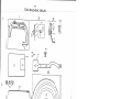
TO REMOVE AND REPLACE THE KNIVES
Tip machine bock orid remove the two screws
G2, Fig. 26. Remove knife rack F2 by sliding it
up out of engagement with knife holder pinion E2.
This causes pinion E2 to rotate so that screw Q3
is accessible. Remove screw Q3. Remove knives
C2 and D2.
To reassemble, position knives C2 and D2 and
replace screw Q3. Mesh first tooth of knife rack
F2 with first tooth of pinion E2. Slide rack down
along driving bar and replace screws G2.
TO ADJUST KNIFE POSITION
AND KNIFE PINION
Fig. 26 shows knife C2 (shuttle thread knife)
and knife D2 (needle thread knife) in stop position.
Teeth in knife holder pinion E2 and knife rack
F2 must be properly meshed without binding or
looseness.
To eliminate binding, loosen the two screws G2
and screw H2. Slide adjusting block J2 down.
To eliminate looseness, loosen the two screws
G2 and screw H2. Slide adjusting block J2 up.
‘
After adjustment, tighten screw H2, reposition
knife rack F2 and tighten screws G2.
J2”;
TO TIME THE KNIFE
To time
knife roller.
knife action,
Tighten nut
‘7.
the knife, loosen nut V. Fig. 25, on
Move knife roller toward left for faster
or toward right for slower knife action.
V.
Q3
Fig. 26. Adjustment
of Knives
TO REMOVE ARM SHAFT END PLAY
1(32”
Before any adjustment is made on the stop mech
anism first check for arm shaft end ploy. End play
should be at a minimum without binding. To remove
end play, loosen arm shaft bushing set screw Q2,
Fig. 31, page 9 and turn hex support screw X2,
Fig. 27 inward. Tighten bushing set screw Q2,
Fig. 31. Recheck for a minimum of end piay with
out binding.
a
K3 !!N3
X2*
J
TO ADJUST THE TRIPPING MECHANISM
(For one or two-notch starting bell crank)
The tripping mechanism
locks starting lever
F3, Fig. 27 into running position by means of bell
crank pawl A2, Fig. 28 and bell crank B2, Fig. 28.
Before adjusting, make sure rock shaft D3, Fig.
28 is free from binding, particularly at upper support
E3, Fig. 29, page 9.
To adjust starting pawl and tripping mechanism,
first loosen socket screw Z, Fig. 28. Set tripping
arm A3, Fig. 25 to trip point X, Fig. 25 and leave
approximately .010” between bell crank B2, Fig. 28
and bell crank paw! A2. Tighten socket screw
Fig. 28.
I
1.
W2
Fig. 27. Removing End Play
z
A?
.011)
TO ADJUST THE STARTING LEVER
132:u
Starting lever F3, Fig. 27, page 8 carries en
gaging arm K2, Fig. 31 and all the recoil absorbing
mechaniSm.
I
C3
With the bell crank pawl A2, in catch C3, Fig.
28, there should be approximately 1/32 inch space
between high point of comminy face of fixed pulley
N3, and interlocking arm K3, as shown in Fig. 27.
D3
To obtain this setting, loosen swivel lock nut
63, Fig. 29 and remove hinge screw H3. Turn swivel
in or out as required. (Each full turn of swivel
equals approximately 1/32 inch of adjustment.)
Replace hinge screw 113 and tighten swivel lock
nut 63.
I
[I
TO ADJUST ‘IV” BELT
Keep belt tension only heavy enough to drive
machine without slipping. Excessive belt tension
will cause erratic stopping, shortening life of belt
and loose pulley bearing.
/
Fig. 28, Tripping Mechanism
With machine in an idle position, adjust belt
tightener, which carries motor, to obtain a distance
of 1-7/8 inches when belt is compressed as shown
in Fig. 30.
TO ADJUST THE ENGAGING ARM
Engaging arm K2, Fig. 31 drives idler pulley
N2 forward and forces “V” belt M2 forward and up
the face of fixed pulley, thereby driving the machine.
I
4
ing Lever Adjustment
With machine in operation, “V” belt M2 must
raise off bottom of idler pulley 1/32 inch, as shown
in Fig. 31.
ro adjust, loosen pinch screw W2 and tap arm
K2 in against engaging button Y2 until “V” belt
raises 1/32 inch when machine is operated. Tighten
screw W2.
WARNING A raise greater than 1/32 inch will
cause excessive belt tension.
-
N2
rims,
Fig. 30. Correct Belt Tension
I
:‘8’7i
Fig. 31. Adjusting the Engaging Arm
I I)
TO TIME THE STOP MOTION
Trip points X and W, Fig. 25, page 8 force powl
A2, Fig. 28, page 9 out of engagement with stcirtirig
bII crank B2, Fig. 28, thereby bring recoil mechan
sm into action to stop machine.
Trip Point X
)
1
sf0
position
—
determines when machine will enter
—
To adjust, bring starting lever F3, Fig. 27,
8 forward until powl A2, Fig. 28 drops into
first catch C3. Then set trip point X, Fig. 25 so
that, when rotating machine by hand, starting lever
F3, Fig. 27 will drop back against fixed pulley
N3, Fig. 27 just after interlocking notch M3, Fig.
27 has possed interlocking arm K3, Fig. 27.
page
Once properly adjusted, trip point X will not
require readjustment except when feed cam is re
timed.
Trip Point W determines speed at which machine
enters stop position
—
Trip point W will usually require readjustment
whenever the machine speed is changed.
F’g. 32. Stop Motion Brake
Excessive speed when entering stop position
will cause rapid wear and breakage of recoil mechan
ism. Therefore, on a machine not equipped with a
brake, check the trip point W often, for as machine
wears in and runs more freely, it will require a
longer coast period.
Adjust trip point W so that machine consistently
enters stop position at minimum speed when sewing
heaviest part of material.
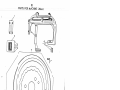
TO INSTALL THE STOP MOTION BRAKE
Remove starting rod adjusting screw H3, Fig. 29,
page 9. Position brake bracket E4 as shown in
Fig. 32 and secure bracket to starting rod with
screw A4. Insert small end of spring support B4 into
small end of spring C4. Insert screw D4 through
bracket until it enters spring support B4. Continue
to turn in screw D4 until tension is applied to spring
C4.
Move starting lever G4 into running position.
Loosen lock screw 114 and turn adjusting stud (ec
centric) J4 until the brake lining K4 clears the
fixed pulley by approximately 1/32 inch. T
tighten lock screw 114.
L
Remove trip point W, Fig. 25, page 8. Run ma
chine and adjust for correct tension on spring C4,
Fig. 32 by turning screw D4 until interlocking arm
K3, Fig. 27, page 8 enters the stop notch quietly.
Then tighten lock screw F4, Fig. 32.
NOTE: As the brake surface becomes glazed
by use, it may be necessary to readjust the tension
on spring C4.
CAUTION: Brake lining must be kept free of oil.
11
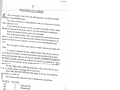
INSTRUC’l’RDNS
When
Vi
FOR
ORDERING
un from Ihu lis
’
1
ts on t;hr follow
ing
[he SVCONI) Co
lumn.
use ONLY the
PART
ito uuuuinlucr stam
ped on a Sewing
.J
c single
Machine Part is
ofii
the
pail. only.
in every case the
number
tvery couiui)llIa lie
u of parl:s sent
out as such has
althou g.h not. sta in
its specific num
ped eu the pa rts
ber, which,
, must be used w
hen orde rin
I a:rti.cwi ar att euiti
g the combinatio
on shoe id be give
n.
n to the following
Wlitui o:i-deriiig
:—
pa i-ts where ther
e is any uncerta
nurube rs, state the
inty concerning
iunctions of the
the correct
parts and the Cl
machine for whi
as
s
and Variety num
ch they arc requ
ber of the
ired, to ensure a
or d er.
cor rect under sta
nding of your
This rut t applie
s as well to parts
that are ordered
mitted.
made as per sam
ple sub
‘l’o siuuiplJy recogn
ition of parts, ex
ploded views of
the mechanism ar
the various sectio
c shown in the sa
ns of
m
e
ill
ustration as the
Facing each illus
ass ernbly of thos
tration page is a
e
pa
rts.
list of parts with
THE FIRST COLU
KEY REFEREN
MN to indicate th
CE NUMBERS IN
e
lo
ca
tion of each part
key numbers are
in the illustratio
foi. reference in
n. These
this manual only
ordering parts.
and are NOT TO
BE USED when
The three digit nu
mber within the
parentheses, af
bers, is a CODE
ter some of the
number, indicatin
part num
g
sty
le
of finish only.
These codes MUS
T BE USED whe
n they appear in
nar.t number, as
the list, and AFT
in the list.
ER the
The following code
s indicate the sty
le of finish used
on listed Parts:
NEW CODE
OLD CODE
803
C
Hardened Only
804
D
Polished Only
805
E
Soft, Not Polished
806
F
Hardened and Po
lished
809
J
Nickel Plated Onl
y
813
R
Phosphate Coatin
g Formed on Surfa
816
ce of Iron and St
U
Zinc Plated
eel
819
X
Black Oxide, for
830
Iron and Steel
A. L.
Heat Treated for
To
833
ughness
A. L. X.
Heat Treated for
Toughness and Bl
850
ack Oxide
X. C.
Hardened and Bl
ack Oxide, for
869
Iro
n
and Steel
Commercial Fini
sh on Allen Type
Screws
this series:
1 to 1500, 50001
to 51500, 140001
to 142000, 200001
1500 are Screw
to Z01500 and 3500
Numbers
01 to
1501 to 1800, 5150
1 to 51800 and 20
1501 to 201800 ar
51801 to 52000,
e Nut Numbers
201801 to 202000
and 351801 to 35
ZOOl to 50000, 52
2000 are Roller
001 to 140000, 14
Numbers
2001 to 190000 an
.ving Machine Pa
d 202001 to 3500
rts
00 are
The figures in the
first column refe
r only to the plat
1 are NOT TO BE
es, illustrating th
USED in ordering.
e parts,
Parts prefixed w
ith a diamond ()
are furnish
:he factory.
ed only when repa
irs are made
-- -
12
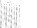
P.A1.TS
A.RCI I C
Ref.
No.
239203
239202
68721
202(819)
239205
239204
68723
3
4
5
6
7
8
9
10
11
12
13
14
15
16
17
18
19
20
21
22
23
24
25
26
27
28
239201
350132(819)
239207
239209
239206
141575(803)
20171 1(803)
350605(869)
Z39Z08
68729
239248
201526(805)
350602(819)
239473
691(819)
239250
23926Z
239501
350645(805)
239474
29
239249
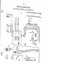
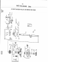
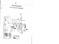
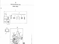
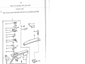
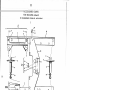
MACIJINI;
269 WH
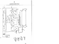
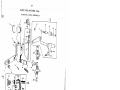
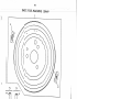
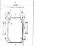
A MP AN]) FEE]) PLATE CARRIER BAR
Pi vt
No.
239210
2
FOR
Description
Arch Clamp complete, Nos. 68729, 201
526(805), 239201., 239203,
239205, 239207, 239209, 239248, +239
249, 239473, 350602(819),
350605(869), two each 201711(803),
239206,andfive 350132(850)
Arch Clamp Foot Shank (left) 239202
with 202(819) and 68721
Foot Shank (left)
Foot (left)
Foot Screw (2)
Arch Clarnp Foot Shank (right) 2392
04 with 202(819) and 68723
Foot Shank (right)
Foot (right)
Foot Retaining Plate
Screw (5)
Frame (universal) with two 239208
Rubbing Block
Spring (medium) (2)
Spring Adjusting Screw (2)
Spring Adjusting Screw Lock Nut (2)
Frame Screw
Frame Dowel Pin (2)
Feed Plate
Plate Carrier Bar with 350645(805)
P.late Nut
Driving Block Screw
Cover Plate (top)
Cover Plate Screw (6)
Stud
Carrier Bar Connecting Arm
Driving Block Pin
Feed Plate Screw Stud
Feed Plate Carrier Bar and Cylinder Cov
er Plate (top) complete,
Nos. Z39Z48, +239249, Z39473 and 35060Z(8
19)
(for repairs only)
Feed Plate Carrier Bar Driving
Block with 239501
.1
I
pz
r=
c-I
c_I
>
2
L
>
>
7.
‘C
rn
z
n
z
>
0
H
U,
-v
>
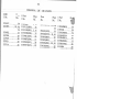
14
iAi’IS
Ak M
Nn.
I
IA Ii,
Na.
401’IS
50650(81)3)
:3
4
5
6
7
8
9
10
11
239:385
239khz
239331
239)30
12166
249915
239143
200363(830)
23477
12
13
14
15
16
17
18
18
19
20
21
22
23
24
25
26
27
28
29
30
31
32
33
34
1065(830)
858(830)
1258(830)
1036(830)
203172
239228
223847
223847
239229
239227
239224
239314
239347
201220(833)
200382(833)
167012
202299
239374
141 l8(833)
239383
200325(803)
53618(805)
239486
167013
35
36
37
38
39
40
41
42
239315
239318
239317
239322
239382
239526
239525
239524
I’C).R
:f’A.Acil1NI;
269 W8
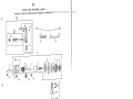
MA(;I IINV PU I J i;y ANI) NI;I:DLI; BAR CRANK
Description
Needle 13d .r C meeting Link
I ,inI’ C;ij) Sc l(V’
1h.ri;id T.i k(—up C rank
TSr (‘ad Tak (‘— [[p Leve camp I ete, No s Z39 330 and 23933 1
Lever Link
Li k — UI) LeV( r
Lever I-huge Pin
Lever I i nk I-tinge Pin with 239143
Lever Link I-huge Pin Oil Packing (wick)
Lever Link I—hinge Pin Set Screw
Needle Bar Crank with 858(830), 1036(830), 1065(830) and 1258(830)
(for Agents only)
Crank Posit [on Screw
Crank Set Screw
Take—up Crank Set Screw
Take-up Crank Position Screw
Friction Washer
Bushing (front)
Bushing (center) Oil Packing (wick)
Bushing (front) Oil Packing (wick)
Bushing Oi.1 Tube (2)
Bushing (center) (for Agents only)
Arm Shaft
Machine Pulley (tight) Key
Vertical Drive Shaft Worm with 200382(833) and 2012Z0(833)
Worm Position Screw
Worm Set Screw
Arm Shaft Bushing (back) (for Agents only)
Bushing (back) Oil Packing (wick)
Machine Pulley (tight) Needle Thrust Bearing
Bushing (back) Support Screw
Washer (2)
Bushing (back) Set Screw
Bushing (back) Support Screw Lock Nut
Machine Pulley (tight)
Arm Shaft Bushing (back) 167012 with 53618(805), 141128(833),
202299, 239374 and two 239383
Machine Pulley Retaining Ring (2)
Machine Pulley (loose) 239317 with 239322
Machine Pulley (loose)
Machine Pulley (loose) Needle Bearing
Machine Pulley (loose) Starting Cap Thrust Plate
Machine Pulley (loose) Starting Cap Thrust Bail Bearing
Machine Pulley (loose) Starting Cap Thrust Button
Machine Pulley (loose) Starting Cap
‘
Q%
C••4
LIJ
U
o
H
z
U
-
z
-4
U
F
ID
0
A
UI
F— Z
I-
7
.1
/
-
I6
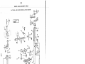
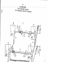
PARTS [‘0 R MACIl IN I
269 W8
I< NI .I’V BAR AN I) OSCI Ii .A’[ [NO ShAFT ASSFMh3LTE
S
Ref.
i.’ci
.
0
1
2
3
4
5
6
7
8
9
10
11
12
13
14
15
16
17
18
19
20
21
22
Z3
24
25
26
27
28
29
30
31
32
33
34
35
35
36
37
38
39
40
41
42
I
ri.
N>.
239251
239253
239261
239260
1
IJcs
t
ioi
cri
i
Rn.iv Bar
239253 with 239260,
Kiiii e Ba r
Adjusting Block
Knife Bar Rack
Scre\V Washer (4)
239261,
three each 202603 arid
3501 32(81
202603
350132(819) Screw (4)
239284
Bushing (front—outer) with 201472(803)
201472(803) Bushing (front—inner) Set Screw
200333(830) Bushing (front—outer) Set Screw
239283
Bushing (front—inner)
239550
Oscillating Shaft
239282
Bushing (back)
239145
Oscillating Shaft Crank complete, Nos. 1636(805), 24050
and 239551
24050
Slide Block complete, Nos. 226(809), 1035(803), 12424 and
19448
226(809) Crank Slide Block Cap Screw
[2424
Crank Slide Block Cap Screw Washer
19448
C rank Slide Block
1035(803) Slide Block Screw Stud
239551
Oscillating Shaft Crank
23955Z
Crank Pin
1636(805) Screw Stud Nut
13275
Oi.l Pad (felt)
39653
Oscillating Rock Shaft
201749(805) Hinge Screw Nut
239280
Oscillating Rock Shaft Hinge Pin 239279 with
23421 and 222583
239279
Hinge Pin
222583
1-Tinge Pin Oil Packing (wick)
23421
Hinge Pin Oil Hole Plug (leather)
200394(803) Hinge Pin Set Screw
908(803) Rod Hinge Screw
20197
Crank Connecting Rod with 125044 and two
896(803) (for Agents only)
896(803)
Rod Cap Screw (2)
125044
Rod Oil Pad (felt)
201083(803) Knife Actuating Lever Screw
213484
Knife Bar Connection Stud Slide Block
213484
Knife Bar Driving Slide Block
200689(803) Slide Block Screw
350447(804) Connection Screw (2)
239257
Knife Bar Connection with 213484 and +2392
58
239251
Knife Actuating Lever
239252
Knife Actuating Lever Link
239146
Oscillating Shaft 239550 with 239145 and 239552
239553
Oscillating Shaft 239550 with 239551 and 239552 (for Agents only)
+239258
Knife Bar Connection Stud
L
17
PARTS FOR MACI-IINF 269w8
1N I I’E I A I A NI.) OSCII JAi’TN(
STIA Ii’ .ASSI M I I IES
31
()
jo
39-
I35—
Li2Ij
3
B
t3rR36
30
-Z6
2
41
13
8
9
20-
to
8
I ‘.AIi
KNlV)
II
No.
2
3
4
3
6
7
8
9
10
11
12
13
14
15
16
17
18
19
20
21
22
23
24
25
26
27
28
29
30
31
32
33
34
35
36
37
38
I ‘i .rt
No.
1 6/009
Z0008’I(8] 9)
239339
239338
1208(809)
5325
239337
5001 8(806)
239368
1198(803)
206133
239372
55459
17825
17830
17826
7298
17827
17828
201711(803)
239367
200138(805)
239236
691(806)
200004(805)
141577(803)
204235
239233
Z00294(81 9)
350618(803)
239234
239221
200582(819)
239223
200064(819)
201 072(805)
167262
1053(806)
+Z39230
$239231
+239220
I’()1.
IvIAC1 lINT;
29W8
tvl-C1llANI()tJS (0V11’S AN)) i’Tl1()A’[ .Pli\’TJ;
1•
I_)vscril)tiou
A:rin CoVer (Iront) with 1053(806) and 167262
CV(W (4)
Throat Plate with 1198(803), 55459, 2001 38(805), 206133, 239367
and 239372
Throat Plate 239337 with 55325 arid two 1208(809)
Needle I lole Bushing Screw (2)
Needle Hole Bushing (46 needle hole)
Throat Plate
Pinion Stud Bracket Screw
Knife Holder complete, Nos. 1198(803), 17825, 55459, 206133 and
239372 (for Agents only)
Screw
Wahr
Knife (Needle Thread)
Knife (Shuttle Thread)
Knife Holder with 17826, 17830 and two 7298
Position Pin
P4 n ion
Pinion Dowe.l Pin (2)
Pinion Stud
Knife Holder Pinion Stud Bracket with 17827
Stud Bracket Screw Nut
Knife (stationary)
Knife (stationary) Screw
Oil Stop Pad (felt)
Screw (4)
Screw (5)
Belt Guard Lock Spring Screw Stud
Position Pin (4)
Cylinder Cover (bottom)
Cylinder Cover (bottom) Screw (2)
Locating Screw (4)
Cylinder Cover (side)
Arm Cover (center)
Arm Cover (center) Screw (2)
Arm Cover (side)
Arm Cover (side) Screw (4)
Cylinder Base Locking Screw
Arm Cover (front) Thread Cutter Knife
Knife Screw
Cylinder
Cylinder Base with 200364(803) and 239361
Arm with two 239229
/
V
(‘4
‘V
\
I?
1-
_;
---
-
3
(‘4
r3
—I,
;—-
I::
1
//
>
-
>
2s)
iL
LU
ihi.
No.
I
2
3
4
5
6
7
8
9
10
11
12
13
14
15
16
17
18
19
20
21
22
23
24
25
26
27
28
29
30
31
32
33
34
35
36
37
38
39
40
41
42
43
44
45
46
47
48
49
I
No.
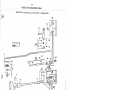
l.All.- VOl< vlA(,IllNl; 2(-)wK
LA[’f;RAI. i\ND lONC;.ll:Ul)INAL ROHK Sl[A11
.$
I )‘ ci.- ipl.i (Hi
01 P;I(:IciIiI (wek) (2,)
I)i’.iv(’ii /\iiii I IiiiI’(’ StII(I \‘itl 2,02<123 (2)
SLl: Serew (2)
I’u(k iii;iJl. ).riven i\.riii (2)
23957<1
I)rfviii Arili Scrt’’,v iI:iid (juide 13[c)clc. (2)
231)2.69
I )riv:i ii A:rin SCrew Stud (2)
239268
1)riv iii A. rin with 350604(809)
:35060.1(869
.15 neli Screw (2)
210805
Waihtr (2)
201652(805) Nut (2)
268072
(3o1 I ar w ttli tWO 200386(803 ) (2
200386( 803) Set Screw (4)
239384
Lo
i
5
tticlijia
n 1 Rock Shaft
51946
RoLler and Stud with 1655(803) and.37310 (2)
200545(803) Link Screw
239266
Lateral Rock Shaft Driven Arm Driving Link
239263
Lateral Pivot Driving Arm with 350600(869)
350600(869) Pinch Screw
201518(805) Link Screw Nut
239264
Lateral Rock Shaft
37310
Washer (2)
1655(803) Nut (2)
239343
Tripping Rock Shaft Lever Arm
200082(805) S c r
239340
Tripping Rock Shaft
239361
Arm Hinge Stud
200364(803) Set Screw
239240
Link Hinge Stud
239241
Link Retaining Ring
239239
Link
239238
Cam and Knife Follower Arm with 239Z39 and 239240
201539(819) Roller Screw Stud Nut
225837
Roller Screw Stud Washer
351886
Knife Arm Roller 201896 with 350634
201896
Arm Roller
350634
Roller Screw Stud
239255
Knife Bar Actuating Rock Shaft
239256
Rock Shaft Bracket
201256(803) Bracket Screw (2)
239363
Bracket Locating Pin
239259-001
Knife Bar Driving Lever with 200034(803)
200034(803) Pinch Screw
234813
Collar with two 201052(833)
201052(833) Set Screw (2)
239344
Tripping Rock Shaft Support
200378(803) Set Screw
239341
Tripping Rock Shaft Connection with 3 50606(869)
350606(869) Pinch Screw
239144
Longitudinal Rock Shaft 239384 with 51946
202’l 2,
)Z(7
1
2i
2003 i5(H0)
2:9205
j
(0
/
C’,
H
0
z
H
b
z
C..
z
C)
0
(I)
—
>
‘I’S
I’( )R
MA (liii N I;
2( W 8
11 ‘I’I 1 I’ IA I A NJ I) A L(1 I C I ,A MP I il’’FINC kOCK SI1i\.I.’’’i’ ASSI’ivlB I ,y
III’’
No.
2.
7
H
1)
10
11
1 2.
13
14
15
16
17
18
19
20
-
21
22
23
24
2.5
26
27
Z8
29
30
31
32
33
34
35
36
37
38
39
40
41
42
43
44
45
No.
2392.
200I .;0(830
Description
iit:1
]‘oclc ;1i1t; \k’I]I 200’130(8_30)
Link Connection Sc:rvw
Nt ud ( I hi r B ii shing (per
9) .1 ressuru Rt’gtilatin Screw
2392 Ii
-;J)J ng
239217
1fti ug Link
I iii 511)11 Release Rod
2392] 3
Posi tin ii Guide with 200072(803), 239Z 17 and 23951 5
7.39 5 1!)
Li ILl ug Link lii nge Pin
21)0072(803
Pinch Screw
2392.76
Connecting Stud 239275-001 with 200086(833) and 239277
2.39275-001
Connecting Stud
200086(833) Stud Pinch Screw
239271
Stud Oi.1 Packing (wick)
239218
Lifting Link Connection
239212
Lifting Bar Bushing (lower)
239211
Arch Clamp Lifting Bar with 176(819)
239273
Needle Bar Bushing (lower)
Z39 272
Needle Bar with 200125(833), 201143(819) and 239376
239390
Thread Wiper (quick acting) complete, Nos. 330(809), 39453, 63837(
141574(803), 200308(803), 239336, 239387 to 239389 (for Agents only,
63837
Arch Clamp Foot Lifter
330(809) Thread Wiper Body Finger Screw
39453
Thread Wiper Body Finger
176(819) Screw
239376
Needle Bar Thread Guide
201 143(8 19) Guide Screw
200125(833) Needle Set Screw
239389
Thread Wiper Body Wire (adjustable)
239336
Wire Clamping Plate
141574(803) Wire Clamping Plate Screw
239387
Thread Wiper Body
200308(803) Body Hinge Screw
239388
Body Support
200337(803) Body Support Set Screw
239487
Starting Lever Lifting Rod
Z3921 6
Lifting Arm with 201256(803)
201256(803) Lifting Arm Pinch Screw
167143
Starting Bell Crank
1 67 144
Crank 167143 with 51657(805), 53617(805), 167154 and 167155
53617(805) Swivel Stud Lock Nut
46
Z39294
Starting Bell Crank F
141065(803) Hinge Screw
47
239295
Pawl Return Spring
239299
Lifting Rod
48
239342
Connection Rod
167154
Starting Rod
49
20 1083(803)
Pawl Hinge Screw
167155
Starting Rod Adjustor
50
259470
Collar with 201188(803)
51657(805) Rod Lock Nut
51
Z01188(803)
Collar Set Screw
(_.liiiii_>
i.itiiig
tiitiflJ
23
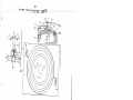
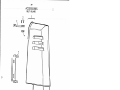
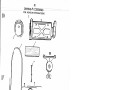
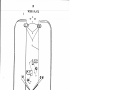
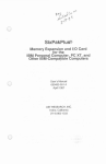
PARTS OR MACHINE 269w8
NEEDIF BAR AND ARCI-I CLAMP LIFTING ROCK SHAFT ASSEMBLY
3)
50
36
r Lf
8
ZJL
‘F;
I
4
I7
ii
3
I NCHS
34
19
20
(4l
32
7
c:ç
293w
24
/28
22—.
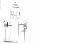
Needle:
Catalog
1628
(68x5)
Size 18
23
-
24
I A R IS
Sit ill’ iJ
1f.
No.
I’. I
No.
2
3
‘1
5
6
7
8
9
10
1 5141
15140
2973
2974
592(805)
2975
224842
591(806)
43725
11
12
13
23500
40028-002
239292
14
15
16
1.7
18
19
20
21
22
23
239290
23928
201148(819)
51381(806)
239291
239289
239365
51403(869)
262061
350606(869)
IOfl
MACi IN 1
!‘,OKKiN AN!) RAC1
269 W8
.ASSIMBLiIS
Dt s(: ri.pI:io fl
ShoW e, 1—11/16 in. cliam.
NTos. 23500, 40028—002 and 43725
Iii ige, Nos. 2973, 2974 and 1 5140
at.ch
I a I.cli I (Ve 1
Latch Lever Lii cr urn Pin
I .aI;c1i Stop Sc rew
Latch Spring
Tci sion Spring
Regulating Screw
Shuttle Bobbin Case with 591(806), 592(805), 2975, 15141 and
224842
Shuttle Bobbin
Shuttle Body
Shuttle Race complete, Nos. 239285, 239289, 239290, two each
51381(806),201148(819) and 239291
Race Ring
Case Position Plate
Case Position Plate Screw
Ring Spring Screw (2)
Ring Spring’(Z)
Body with 239365
Body Oiling Felt
Body Screw (2)
Shuttle Driver (central bobbin) with 350606(869)
(central bobbin) Pinch Screw
,
25
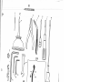
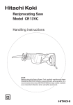
PARTS FOR MAC[1IN 269
w8
SIll 11,1 LE BO1IHIN
AND RACE ASSEM
BLIES
34I
/
I
22{23
1
[F
i
[NCHES
‘21
‘
I ‘A
I
i’’( 1 lviJ\ ( I I I’ 2(e) \‘V 8
SIA II’IN
IJ;v I’I \;I;ftiIjJ,y
Ne.
1
2
3
‘1
5
6
7
8
9
10
11
12
13
14
15
16
17
18
19
20
21
22
23
24
25
26
27
28
29
30
31
32
33
34
35
36
37
38
39
40
41
42
43
44
45
Ne.
235)2’5)6
I
r
ii )t:
C)
S
L[
ii.iiig I
with 2003b1(81)3)
23) ;o•i
I fling .i ng
350 [12(80’)) SJ)1ing Screw Stud upper) (2)
(
2 [4()53
Spring (2)
201442
Ik
tion Sen w 1 in
167158
Step Rod BCII1Ip(r SCpa ratiu
’ Washer (8)
1
239303
Operating I cver A r fli
201 422(80:3) Arm Stud Screw
Z0[356(805) Scr iw Stud (lower)
239301
Bushing
200364(803) Set Screw
239133
Starting Lever Arm and Rock Shaft (adjust
able) with 423(830),l650(8C
20135(803), 201442(803), 201525(805),
228810, 228812 and 232837
201525(805) Spring Stud Nut
228810
Spring Screw Stud
228812
Tension Pulley
232837
Tension Pulley Retaining Screw Washer
201135(803) Tension Pulley Retaining Screw
239159
Interlocking Arm
239517
Interlocking Arm Stop Rod
202342
Stop Rod Hinge Pin Tension Spring
239518
Stop Rod Hinge Pin
131022
Stop Rod Bumper (rubber) (4)
239310
Stop Rod Swivel
228032
Stop Rod Swivel Washer
1518(805) Nut (2)
239549
Stop Motion Brake complete, Nos. 167229, 200428(803), 20]. 075(80
6),
223812, 239511 to 239513, 239557 and 350676(850) (for Agents
only)
239557
Brake Shoe Support 239554, 239556 and two 239555 with 239508
239554
Stop Motion Brake Shoe
239556
Brake Shoe Support
201075(806) Support Hinge Screw
223812
Support Spring
239511
Support Bracket with 200110(804) and 350411(803)
350676(850) Bracket Hinge Screw
239513
Support Bracket Stud (eccentric)
200110(804) Support Bracket Stud Screw
167229
Support Bracket Pressure Spring
239512
Pressure Spring Sleeve
35041 1(803) Pressure Spring Adjusting Screw Pinch Screw
200428(803) Pressure Spring Adjusting Screw
239519
Stop Cam Interlocking Arm Stop Rod Hinge Pin Retainer
239520
Interlocking Arm complete, Nos. 202342 and 239517 to 239519
201527(803) Swivel Nut
423(830) Starting Lever Arm and Rock Shaft Stop Screw
1650(805) Stop Screw Lock Nut
239555
Brake Shoe Rivet (2)
S
—
N
N
N
N
N
d
i
N
N
‘
\
>
>
(••)
-
rn
<
20
H
>
H
ZLfl
1ARr;
I:N A( IN A 3M,
i’013
MACi1IN1
ii 1k VAD GUIDI;,
3o)
W5
11 I;’I’AIN I135 AND
‘I I;Nb I(N (([v1 UI
N.
I i
Nu.
—‘:3
I
/,39.6
3
(
‘/
13
9
10
11
12
13
1i
15
16
1.7
18
19
-t
20
21
22
23
24
25
26
27
28
2.9
30
31
32
33
00 3 / /(1W 3)
082
2/02/b
].‘i I 5/ (80.
2102
32572
2103
1 bbO(803
239328
200366(1319)
200442(803)
210954
200582(819)
270080
350559(819)
271018
223711
223710
200397(833)
200582(819)
2.10993
223844
21 0957
210958
239381
Z39379
239320
239321
350600(869)
239380
201747(819)
N
Disc r.plioii
1560(803), 2103, 32572, 5Z08Z,
141 57(803), 210278, 270281 ;iiicl two 2102
uI,I.or with 201) 377(803)
1
:J) rfl) R&’
l(Ju;ion Stud $tt Set-ew
r(;I (I F1 IIj) Spriu8
[‘cii H Oil I-i (i Hi Ii Piii
ion
IliHioli Disc (2)
‘F i.ii siou .Ri1 casing Di sc
1(11 jo ii S p ru i g
Tension Thuiiib Nut
jension Thread Guard
‘[‘crision Thread Guard Set Screw
Thread Take—up Spring Regulator Set Screw
Thread Guide
Thread Guide Screw
Thr cad Retain ci- (front)
Thread Retainer Screw (2)
Thread Retainer (back)
Thread Retainer (lower) complete, Nos. 210957, 210958,
210993, 223710 and 223844
Thread Retainer (lower) with 200397(833)
Retainer Stud Set Screw
Retainer Screw (2)
Sic eve
Spring
Stud
Stud Collar
Machine Pulley (loose) Engaging Arm 239379 with 239380
Engaging Arm with 239320, 239321 and 350600(869)
Wear Block
Wear Block Pin
Pinch Screw
Machine Pulley (loose) Engaging Arm Stud with 201747(819)
I’enHJuI) corn i.[vte,
Lock Nut
[‘los.
(I
C
-D
LIJ
0
-
-4
H
LZ
LI
N
ID
C%J
A
0
Di
w
‘I.,
-
Di
\ \\
.31)
PARiS
V I; k ‘1’ [CA I
lOR
MACI tIN I;
269W8
I )k 1 V I; Si IA 1”[ A Ni) F V V 1)—A Ni)—KNJFE—1)RTVING CAM
-
Re[.
No.
1
2
3
4
5
6
7
8
9
10
11
12
13
14
15
16
17
.1 ;i rt;
No.
239348
200362(803)
200354(830)
239346
239364
2393’iS
239523
202005
350627(869)
239522
239245
239237
239247
200064(803)
350601(803)
210805
350600(869)
Dcsc ription
Worni Gear with 200354(830) and 200362(803)
Worn (x.ear Set: Screw
Worm Gear Pcsition Screw
Bu.sli:ing (upper)
B u shing (lower)
Vtrticai.Dr ive Shaft
Bracket
Bracket; Scr evv Washer
Bracket Scrcw
Supporting Gear with 239245
Locating Pin
Feed and Knife Driving Cam with 200064(803) and 239247
Tripping Point
Tripping Point Screw
Supporting Gear Screw
Mounting Screw Washer (3)
Mounting Screw
(
Cr)
UJ;r
I’A1’I
l(>F<
(
RH.
No.
No.
1
228800
2
167292
3
4
5
462(8.30)
228798
200084(850)
6
7
268122
5989
8
9
10
11
12
13
14
418(804)
2455
10141
1562(819)
228792
350238(804)
239158
15
16
172
228793
200436(803)
228795
249716
201 256(803)
239157
228796
50628(809)
225459
225458
50356(804)
1620(819)
202478
200056(805)
225444
200299(819)
228794
239558
18
19
21
22
23
24
25
26
27
28
29
30
31
32
)K
N4A(:iiIN;
IN
269V8
VV IN )I R
I )sc .I.iI)tiU1)
I iglil: and I’()bbill \‘Viiider .[hi’v;i ci Tens ion AcIjttstiru Stud
B racket 1 67292 w:ith 5989, 228/98 and 268122
I ght nicI 13oIbin W:incler ‘[h.read ‘1 ciision Adjusl:irig Stud
Bracket wit:li 462(830)
1eiisicjti Adjusting Stud Set Screw
‘I ens ion Adjusting Stud
Light and Bobbin Winder Thread Tension Adjusting Stud
Bracket Set Screw
Tension Guide
Bobbin Winder Thread Tens ion complete, Nos. 418(804),
1562(819), 10141 and two 2455
Tension Stud
Tension Disc (2)
Tension Spring
Tension Thumb Nut
Brake (leather)
Brake Screw (2)
Bobbin Winder complete, Nos. 1620(819), 50356(804),
50628(809), 200056(805), 200299(819), 202478, 225444,
2Z8793 to 228796, 239157, 249716 and two 225459
Pulley with 200436(803)
Pulley Set Screw
Spindle Housing
Spindle I-lousing Spring
Bracket Screw
Bracket
Stop Latch Thumb Lever Plate
Stop Latch Thumb Lever Plate Screw
Joint Stud (2)
Stop Latch Thumb Lever
Spindle Housing Screw
Spindle Housing Screw Nut
Stop Latch Trip Lever
Stop Latch Screw
Stop Latch
Stop Latch Trip Lever Hinge Screw
Spindle with 239558
Bobbin Winder Bobbin Locating Pin
22547.
33
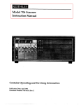
PARTS EOR MACHINE
269w8
EOi3fIN WINDER
7
/
urnnJu
3
1/
‘4
H,,\gIL;
Si\ M V AS /\ 0(1
R’.
Nt.
I ii.
No.
()
/\
21’)\VS
ANT)
Z69v]7
I’d JIlON C LAML
Mi’ UN M A H TINT; 269 W8 W Jill Ill I; FOIl OWING IX( vPi 0 )NS
‘
2 9I 2l
2
3
4
5
(H
IA(Hi1NI;g
6 591$
i 3659’)
Ii I 91)
I 36 (,00
1 5 3 /9
7
8
9
10
11
12
13
14
15
I 36601
1366(32
136603
124732
17710
1176(1319)
6 87 99
124733
16
17
18
19
20
zi
22
23
24
25
26
27
28
29
30
31
32
33
34
35
36
37
38
39
40
41
124734
124735
239123
50117(809)
1484(809)
99(813)
39241
239572
1177(819)
17714
1178(819)
39335
39242
136608
124737
124738
1182(809)
17718
124739
50237(810)
17719
1181(819)
63742
17720
63741
1199(819)
/28(8 19)
l)escriptioii
(11]]1 (‘Ilpiete, Nos. 99(1313), 1181(809), 1183(809), I 199(81’
1771’), 39242, 50237(810), 63741, 124732, 1 24733, 124734, 1 Z473?
I 24738, 1 24739, 136 599, 1 36602, 1 36608, two (tch 1175(805),
17718 a,id four 1182(809), i P
C ç,f 239210
1
i’,iittoii
110 tt( Hi CIiiip (hit.) with 17723, 45329 and three 36696
1, i ti i
CIoiip (left) 136598 with 228(819) and 136600
(H LIlflj) ILC1 1ui (6)
( I LI] p (I eft) Spring
ring l()SitiO]l lin (2)
Spring Screw (2.)
11’ittou Clamp (right) with 17723, 45329 and three 36696
ut toli Clamp (right) 136601 with 228(819) and 136603
C Ia top (right) Spring
CI LLO113 Arm with 17714 and 68799
Arm I--Tinge Plate
Arm Hinge Plate Screw
.Arni F-Took
Clamp Opening Lever
Opning LLver Bracket
Openmg Lever Contact Piece
Contact Piece Arm
Contact Piece Arm Screw
Contact Piece Screw
Opening Lever Hinge Screw
Clamp Pre
Spring
Spring Bracket
Bracket Screw
Spring Guide Block
Spring Screw
Spring Screw Plate
Clamp Spreader
Clamp Stop with 17720 and 63742
Spreader Lever
Spreader Lever Adjusting Plate
Screw (4)
Washer (3)
Spreader Lever Stop
Stop Position Screw
Spreader Spring
Spring Screw Stud
Spreader Steady Pin (long)
Spreader Steady Pin (short)
42
Spreader Thumb Plate
43
Thumb Plate Screw
44
(
ssure
—
1183(819)
17723
1175(819)
Stop Screw
Clamp Stud (2)
Clamp Hinge Scre
zm
0
H
C
2
‘1
z
>
2
>
>
>
-r
-D
>
2
>
>
LI
I
-‘I)
-,
PARTS FOJ. MACIT1N[;S 2.69W
1 AND 269 W17
10k STII.CI1ING 2 011 4 IIOLL BUTTONS
SAMV AS MACIIINI; Zb)W8 WiTH T1TV FOLLOWING l;XC1;PTIONS:
Rel.
No.
1
2
3
4
5
6
7
8
9
10
11
12
13
14
15
16
17
18
19
20
21
22
23
24
25
26
27
28
29
30
31
32
I >;i r
Nu.
239537
/
Description
l)evic V complete, with graduations and two external hand
operated I (VI r s for quick adjusting of the lateral and longitudinal
nuchanisro, Nus. 1654(803), 141550(830), 239533, 239534,
239535, 2.39536, two each 1620(805), 141545(830), 194328,
2.00362(803), 201783(803) and three each 202248 and 20262.2..
239533
Cylinder Cover (side), in place of 239234
2.39534
Late i-al Adj us t::i rig Lever
1415115(830) Hinge Screw (2)
1620(805) Hinge Screw Nut (2)
239583
Lateral Rock Shaft Driven Arm
Longitudina.1 Adj usting Lever
239535
239536
Lon gitudinal Adj U sting Lever Handle
141550(830) Lever 1-linge Screw
1654(803) Hinge Screw Nut
167287
Longitudinal Feed Plate Carrier Bar Positioner
202248
Hinge Spring Washer (3)
202.622
1-linge Screw Washer (3)
201783(803) Screw Stud Nut (2)
200362(803) Screw Stud Locking Screw (2)
194328
Screw Stud Washer (2)
2.39586
Feed Plate, in place of 68729
239573
Feed Plate Carrier Bar with 141560(805), in place of 239248
1654(803) Feed Plate Nut, in place of 201526(805)
141560(805) Feed Plate Screw Stud, in place of 350645(805)
239151
Shuttle Race Body with 239365, in place of 239289
210993
Thread Retainer Sleeve
272208
Thread Retainer Spring
210957
Thread Retainer Stud, in place of 270080
210958
Thread Retainer Stud Collar
239121
Thread Wiper Body Support 124777 with 1207(803)
124777
Thread Wiper Body Support, in place of 239388
1207(803) Thread Wiper Body Hinge Screw, in place of 200308(803)
200084
Cylinder Cover (side) Screw (2)
239269
2.39574
239365
Iuliti sting
Screw Stud (2)
Screw Stud Guide Block (2)
Shuttle Race Body Oiling Felt
Catalog 1627 Needle (68x3) Size 16
239152
Shuttle Race complete, Nos. 239151, 239285, 239290, two each
51381(806), 201148(819) and 239291, in place of 239292 (for Agent
only)
239122
Thread Wiper (quick acting) complete, Nos. 330(809), 1207(803),
39453, 63837, 124777, 141574(803), 239336, 239387 and 239389
(for Agents only)
Ii
NJ_g
9
6?
c —€
Ii
I—
ç,— 9!
oc —ci
O
—-
y
9
(‘
(IN V
£
ci
t71
£ —ç
c2>— 91
w--—-
ci
-N()i]iI)\,i )Nii\Y
i’iOi :iiii iii.IA’\ H/vh
g’
-NOiLii
1.1 iV
INiIi:)Vi’
\‘ :ii’N\/!;
110?? I’ NO ? 0Niii:)III
K),i
N (‘i?
N ii )\/ i”
H ( ) 1
0 H
: H
I ‘ARTS
EUl
MACI TIN i:s
269W 5
AND
269 WI 7
FOk SIlT Cli INC 2 OR 4 hOLE BUTTONS
SAMV AS 269W8 w.IT:l1 TilE FOLLOWiNG EXCEPTIONS:
PARIS FOR MAChINE 269W5 ONLY
23957 I.
2
3
200064(803)
239247
239 i 31
1’ ced and Knife Driving Cam with two each 200064(803) and 239247,
(X stitch) Regular, in place of 239237
Tripping Point Screw (2)
Tripping Point (2)
feed and Knife Driving Cam with two each 200064(803) and 239247,
( stitch), in place of 239237
PARTS FOR MACHINE 269 Wl7 ONLY
1
239142
4
239577
5
6
7
8
9
10
11
12
450(833)
453(830)
239578
140732(830)
448(830)
239132-001
239141
17829
239154
239156
Feed and Knife Driving Cam with two each 200064(803) and 239247,
in place of 239237
Vertical Drive Shaft Worm with 450(833) and 453(830), in place of
239347
Vertical Drive Shaft Worm Position Screw, in place of ZO1ZZO(833)
Vertical Drive Shaft Worm Set Screw, in place of 200382(833)
Vertical Drive Shaft Worm Gear with 448(830) and 140732(830),
in place of 239348
Vertical Drive Shaft Worm Gear Position Screw, in place of 200354(8
Vertical Drive Shaft Worm Gear Set Screw, in place of Z00362(803)
Lateral Feed Plate Carrier Bar Positioner
Throat Plate Needle Hole Bushing, in place of 55325
Knife Thread Bolder, in place of 206133
Throat Plate 239337 with 239141 and two 1208(809), in place of
239338
Throat Plate 239154 with 1198(803), 17825, 17828, 17829, 50018(806)
55459, 200138(805), 201711(803), 239367 and 239372, in place of
239339
39
)‘AkI;
‘ok
vIACI(INTS
10k Ilic’.(llN(;
A;
(‘)VVk \V ITI I
[I lI’
Z6)’V
i\Ni)
Zb)\V
7
(I ‘1 1IOLI; IU’[TON
I(I 1 (,)\VIN( .IX(,I’i’I’i
QN’:
4
7
II
10
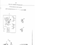
[‘A Rl:S
i’Oi.{
l’().R
hA MI AS MACI liNk
Rei.
No.
I
ci
No.
I
2
3
4
5
6
7
8
9
10
11
12
13
239465
239202
202(819)
239463
239466
239204
39304
239469
239337
239468
1208(809)
239471
14
15
16
200382(833)
201220(833)
239472
17
18
19
200362(803)
Z00354(830)
239461
20
21
200064(803)
239247
239464
239467
239470
Cat. 3072
MAChINE
5110 I
269 W7
TA(;K NC
9W8 W liii TI I I FOLLOWING 1;XC1;PT1ONS:
I)vscriptioii
A cli (
Foot. hhuik (left:) Z39202 with 202(819) and 239463
loot Shank (lift)
loot Screw (2)
Arch Clamp Foot (left)
Arch Clamp Foot Shank (right) 239204 with 202(819) and 239464
Foot Shank ( right)
Arch Clamp Foot (right)
Feud Plate
Throat Plate 239337 with 239468 and two 1208(809)
Throat P[atc
Throat Plate Needle Hole Bushing (40 needle hole)
Needle 1-Jole Bushing Screw (2)
Vertica.l Drive Shaft Worm with 200382(833) and 201220(833), in
place of 239347
Worm Set Screw
Worm Position Screw
Vertical Drive Shaft Worm Gear with 200354(830) and 200362(803),
in place of 239348
Worm Gear Set Screw
Worm Gear Position Screw
Feed and Knife Driving Cam with two each 239247 and 200064(803),
in place of 239237
Tripping Point Screw
Tripping Point
Arch Clamp complete, Nos. 39304, 201526(805), 239201, 239207,
Z39209, 239248, •239249, 239465, 239466, 239473, 350602(819),
350605(869), two each 141575(803), 201711(803), 239206 andfive
350132(850), in place of 239210
Throat Plate complete, Nos. 17828, 50018(806), 200138(805),
201711(803), 239367, 239368 and 239469, in place of 239339
Needle (16x100) Size 16
41
FOR MACI-HNIE 269w7
1’()R SHOE JACKING
SAM1 AS MACIIIN[ NO.
269W 8 WITH ‘1’JJ1 [iOLI ow1N(;
EXCEPl’IONS:
5
9
-12
PARr S
F OR
MJ\ Cli IN.I
.1.01< I.A l<.R,[NG BUTtON I 10 LES,
269 W 9
FASI’ [NJNG BOWS AND OTI-IER
0iNA1v1lNT S ON SI-TOIS OR GARMLNTS.
(
SAM!; AS MACHINE Z69W8 W1TI.1 TilE FOLLOWING EXCEPTIONS:
Ref.
No.
.1 t- I.
No.
1
239406
2
3
239247
200064(803)
55326
239403
239202
202(819)
239401
239404
239204
239402
18459
55458
210993
272Z08
210957
210958
4
5
6
7
8
9
10
11
12
13
14
15
16
17
239405
239532
239126
239127
Description
Feed and Knife Driving Cam with two each 239247 and 200064(803),
in place of 239237
Iripping Point (2)
Tripping Point Screw (2)
Throat Plate Needle I-IoIe Bushing
Arch Clamp Foot Shank ([eft) 239202 with 202(819) and 239401
Foot Shank (left)
Foot Screw (2)
Foot (left)
Arch Clamp Foot Shank (right) 239204 with 202(819) and 239402
Foot Shank (right)
Foot (right)
Feed Plate
Knife (needle thread), in place of 239372
Thread Retainer Sleeve
Thread Retainer Spring
Thread Retainer Stud, in place of 270080
Thread Retainer Stud Collar
Arch Clamp complete, Nos. 18459, 201526(805), 239201, 239207,
Z39209, 239Z48,239249, 239403, 239404, 239473, 350602(819),
350605(869), two each 141575(803), 201711(803), 239206, and
five 350132(850), in place of 239Z10
Knife Holder complete, Nos. 119 8(803), 17825, 55458, 55459,
206133 (for Agents only), in place of 239368
Throat Plate Z39337 with 55326 and two 1208(809), in place of
239338
Throat Plate 239126 with 1198(803), 178Z5, 17828, 50018(806),
55459, 200138(805), 201711(803), 206133 and 239367, in place
of 239339
“I
6
6
M
9Z
9I-
I
1
NHDVW NOd SflIVd
EP
)j\
VOl KARkINC,
SAM I
lel.
I”To.
.
I ‘. r
No.
2.39415
239419
239411
23941 2
2392DB
124906
239414
8
2392.47
200064(803)
239413
239504
I( )R
t’v’l ALl uN I;
2.69 Wi I
SlWINC SIRAPS ON 1JNI)VRWE.AR,
AS MACI II NV 2.69w 8 Will I Ii IV 10
1
2
3
4
5
6
7
9
IS
i:TC.
I 0WiN0 EXCIJ-TIONS:
Description
A rch Clamp loot. Retajoing Plate
Feed Plate
Arch Clamp ‘oot (solid)
A rch Clamp Frame (offset universal) with two 2392.08
lranie Dowel Pin (2)
Arch Clamp Foot Lifter
Feed and Knife Driving Cam with 239247 and 2.00064(803),
of 239237
Tripping Point
Tripp:ing Point Screw
in place
Arch Clamp complete, Nos. 141575(805), 201526(805), 201711(803),
239206,
239209, 239248, 239411, 239412, 239415, 239419,
239473, 350602(819), 350605(869) and five 350132(819), in place
of 239210
Thread Wiper (quick acting) complete; Nos. 330(809), 39453, 124906,
141574(803), 200308(803), 239336, 239387 to 239389 (for Agents
‘)
only), in place of 239390
PARTS USED ON MACHINE 269W11 WHEN SPLIT FEET ARE NECESSARY
239418
239481
Arch Clamp Foot (left)
Arch Clamp Foot Shank (left) 239202 with 202(819) and 239418
239417
239482
Arch Clamp Foot (right)
Arch Clamp Foot Shank (right) 239204 with 202(8 19) and 239417
239483
Arch Clamp complete, Nos. 20152.6(805), 239201, 239207, 239209,
239248, •239249, 239419, 239473, 239481, 239482, 350602(819),
350605(869), two each 141575(805), Z01711(803), 239206, and
five 350 132(819), in place of 239413
o
))
M
I
&
9TflH
I
DVW iO1 S.UJVd
ij
1A k.’I’S
1()R
TvlAC1IIN I
Z(’) WI 2
VoI< LA kLIN(; .[()CKII’S ANI) (iLNI;RA L T3AJ{—TAC.K[Nc; Ol>VRATTON5
oliS VRS, S I_SACKS,
WORK i\ND SPOR’l’ c;LO’.FIIING,
UN1I’OR MS ANT) O’i’}iV R GARMIN’i’S.
SA ML AS MACI TINI
Ref.
No.
.1’; rI.
No.
1
239559
2
239471
3
239472
4
5
6
7
8
9
239247
200064(803)
200382(833)
201220(833)
200362(803)
200354(830)
Z69W8 Will! Ti-IF FOLLOWING LXCEPTIONS:
Dc sc r ipt:io
1 (cci and Knife Driving Cam with 239247 and 200064(803), in
iact of 239237
Vertical Drive Shaft Worm with 200382(833) and 201220(833), in
pLLCC of 239347
Vertical Drive Shaft Worm Gear with 200354(830) and 200362(803),
in place of 239348
T rippng Point
Tripping Point Screw
Worm Set Screw
Worm Position Screw
Worm Gear Set Screw
Worm Gear Position Screw
I
47
1’AkIS I’OI MACIflNI: Z()
WiZ
V() lAN(
( )N
i It )1j
ANI
R;, S I ,ACKS,
(;I;NI1Al JA1—rA(I1N(
; ()I’IiAIiONTS
W()RK A ND SPORT C LOTI
HNG,
Ii Ni I’()RfvlS A NI) O[11IR
CIA R1’.’l lN’IS.
2
A.kTV
F’Oi’
i’Ol
MACI I]NV
-I )V
26’)W ii
LACKING
A M V A MAC I IN V Z() WH W [‘I’ll
‘[1 I V FOLLOWING VXCVPT1ONS:
No.
No.
1
Z3)4bZ
2.
3
ZOOO64(U)3)
2.3)Z’17
Cal.. 3072.
I)escript;iori
V (‘(ci ;uid Kn ii’ J)jvjnr Cam with two
each Z39Z47 and OOO64($O3
in j)iaC(’ of Z3)Z37
‘iriJ)pil1g J?oint Scri’’v (Z)
‘i’rl)pifl;
1k)iiIt
(Z)
N’.L1 (16x100) Size 16
),
71
rn
--
r)
z
>
C
LI
H
-C
>
‘0
.1
1.5
iOi.
MACII[NE
lOP PAPP1NG .I>()(k11’S ON CI
VN IJA I
26) W26
TIlING ANI) OTI11R
IA1U I NC A N I) TACKING OPNRATION
S
SAM V AS MA( i1 IN V 2W) W8 WIt 1.1 ‘liii:
i’OLLO WING I;XCEPTIONS:
I i if.
No.
1
239130
2
2:39422
3
239423
4
5
6
7
8
9
10
206133
239485
140352(803)
200382(833)
201220(833)
200362(803)
200354(830)
Dc sc ription
iced and Knife Driving Cam with
239485 and three each 140352(803)
i.iid 2061 3 3, in place of 239237
Vertical Drive Shaft Worm with 200382(8
33) and 201220(833), in
place (ii 239347
Vertical Drive Shaft Worm Gear with 2003
54(830) and 200362(803),
in place of 239348
Tripping Point Screw Washer (3)
Tripping Point
TrippLng Point Screw (3)
Worm Set Screw
Worm Position Screw
W o r m Ge a r S e t S c r ew
Worm Gear Position Screw
r
/
‘C
c.
m
z
>
a
Lfl
>
F;
2
I. /\ 1<
.I( ).R iv! A C! 1TNJ 2.69 W .38
I()I l/\I8I[\k I[ JIl’ON!lI()!!;S I[\1 (1O11I1N(
siii AS NIA(:IIINI: /(9VV6 WI’[’ll !lJI .VQl1)VVTN
( lx(1;I’lIONS
:
LI
N.
I
3
4
5
6
7
8
9
10
11
12
13
14
15
16
17
18
19
20
21
Z2
23
24
25
26
27
28
29
30
31
32
33
34
1);c ription
639%
A ruli ‘‘i’ l)Ot. 1’I!t 6.3984 ‘itJi 51041(80.3), 64954,
64955,
63986, two (aclI 1 90(809), 910(830) and I 601(809)
9 I I) ( 13. 0)
I.l. Aiju;tui’ ScJ(W (2.)
I 6(11 (110)) .A.I;LtiuI S(.J:(V/ NJi1. (Z)
6 -198 3
AdjLIstn Sc rew B ac1cI:
5
190(809) Adjusting Screw BricIcet Screw (2)
1611 (00i)
loot. Roller LLl( Screw Stud Nut: (2)
51854
loot: Rn lIe r and Screw Stud (eccentric) (2) with 1611(805)
V sit I iate with 1 7959
51 04[(803) loot. Sj) ri tig Screw
17959
loot Lifting Stud
63986
loot
ring
63955
Arch Clamp Foot (right) with 51854
63954
Arch Clamp Foot (left) with 51854
63949
Bell Crank Bracket
183(809) Bull Crank Bracket Screw (2)
239454
Bell Crank Connecting Rod Stop
201535(805) BcIl Crank Connecting Rod Stop Nut
239453
13el.l Crank Connecting Rod
28(803) Bell Crank 1-linge Screw
141(803) Pressure Spring Regulating Screw
63987
Clamp Pressure Spring
788(804) Pressure Spring Screw Stud
239455
Arch Clamp Frame (universal) with two 239208
167214
Starting Bell Crank, in place of 167143
167215
Crank 167214 with 51657(803), 53617(805), 167154 and
167155
239502
Arch Clamp Foot Lifter
239450
Feed and Knife Driving Cam with two each 239247 and 20006
4(803),
in place of 239237
405(803) Locating Finger Screw
35
200064(8 03) Tripping Point Screw
(
63947
Finger with +63969
36
239247
Tripping Point (2)
63965
Feed Plate
37
239208
Frame Dowel Pin (2)
63957
Foot Plate Cap (lower)
38
167155
Starting Rod Adjustor
63958
Foot Plate Cap (upper)
39
51657
Rod Lock Nut
63953
Clamp Closing Slide
40
167154
Starting Rod
239451
Bell Crank with +239452
41
53617
Swivel Stud Lock Nut
+63969
Arch Clamp Bar Locating Finger Pointer
+239452
Arch Clamp Closing Bell Crank Scud
239456
Arch Clamp complete, Nos. 28(803), 141(803), 405(80
5), 788(804),
63947, 63949, 63953, 63957, 63958, 63965, 63985, 63987,
201526(805), 239248, +239249, 239451, Z39455,
two each 183(809)
350605(869) and four 350132(819), in place of Z39Z10
239503
Thread Wiper (quick acting) complete, Nos. 330(809),
39453,
141574(803), 200308(803), 239336, 239387 to 239389
, and
239502, in place of 239390
..
r)
C,’
z
>
0
-n
H
>
Si
I A 1<15
.10.1<
.M.A(.iI[NlS
269W38
ANI)
269 W39
SAMI: AS MAc.! llNl ?9WH WITH ‘[LIV VOLLOWING VXCFPTIONS:
Ref.
No.
I ri.
No.
1
2.39.394
2
3
4
5
6
7
8
9
201 ‘111(80.3)
742(819)
239.393
691(819)
239391
2:39392
200400(803)
201524(803)
I.)esc: ri
)tiofl
1
Work .I:l.Lt( coiiip.[et e, No s 239391, two each 742(819 ), 200400(803),
20! 524(80.3), 20171 1(803), 239392, 239393 and six 691(819)
Work Plate 5
uppo rt Screw Nut (2)
W uric I i.ate Support Strap Sc rew (2)
Work Plate Support: Strap (2)
Screw (6)
Work Plate
Work P Ia. I: e B L’ C Ice t ( 2
Work Plate Adjusting Screw (2)
Work Plate Adjusting Screw Nut (2)
.
55
PARTS FOR MACI-lINES 269w38
AND 269w39
WORK PLATE
A
56
‘A i’li l)l IvIACiHNI
2())W3)
l’Jl ‘l’/\(l’I1\R Bl:l:l l()Ol’S .)N
lRolJSl:iS, S3lIeC1<.S, SI>()i’JS
W 1;Ai,
ii l ‘i’, l;’l’(
SAkil; AS N’IA(IllNll ?9\’VS VVI
1ll ‘llll l’()liO’vViNC lXCll’[.lQN
S:
Re
No.
I
2
3
4
5
(i
7
8
9
10
11
12
13
14
15
16
17
18
19
20
21
22
23
24
25
26
Z7
28
29
30
31
32
33
34
N
-
942’)
239208
239I1 3
(
I )e se ri pt
i
ii
Arch Clamp .1’r;iine (oUxet. universal)
wrt:h l:Wo 239208
.Jri nie Dowel Pin (2
Tiu-iad \Aliper (cpck ct.ing) (;olnjJlete,
NUS. 141574(803), 200308(803
239330, 239387 to 239381,) and 239424 (for
Agents only), LII place of
239390
239388
Body 1
S
i
po
ii
rt
200308(803) Body hinge Screw
141 574(803) Wire Ciniping Plate
Screw
239310)
TSr cad Wi ocr Body Wire (adj ii stab
le)
239336
Wire Clarnping Plate
239387
Thread Wiper Body
239424
Arch Clamp Foot Lifier with 2394
42, in place of 63837
239442
Thread Wiper F uic r urn Pin
239428
Arch Clamp Foot Shank completc,
Nos. 1094(803), 200160(819),
239426, 239427 and 239431
239426
Arch Clamp Foot Shank
239427
Arch Clamp Foot Shank Arm
1094(803) Arch Clamp Foo
t Shank Arm Screw
200160(819) Arch Clamp Foot Scr
ew
239431
t.
Arch Clamp Foot
239425
A:rch Clamp Foot Retaining Plate
239476
Feed Plate
239448
Feed Plate Carrier Bar Pin (2)
239477
Feed Plate Carrier Bar
239441
Cylinder Cover (bottom)
239435
Feed and Knife Driving Cam wit
h 200064(803) and 239247
141066(803) Cylinder Base loca
ting Screw (4), in place of 3506
18
200064(803) Tripping Point Scr
ew
239247
Tripping Point
239440
Cylinder Base Leg
239422
Vertical Drive Shaft Worm wit
h 200382(833) and 201220(833)
200382(833) Worm Set Screw
201220(833) Worm Position
Screw
239423
Worm Gear with 200354(830) and
200362(803)
200362(803) Worm Gear Set
Screw
200354(830) Worm Gear Positio
n Screw
35060Z(819)
Driving Block Screw
+239439
Cylinder Base with 200364(803),
239361 and 239440, in place of
+239231
239430
Arch Clamp complete, Nos. 1415
75(803), 201711(803), 2392
06,
239209, +239249, 239425, 239428,
239429, 239473, 239476,
239477, 350602(819), 350605(869)
and five 350132(819), in
place of 239210
0
6CM69 NHDVW
?J01
.Acc.l;Sso.kJ.1;S
1./[’
Ret
No.
1. i. ii.
No.
G[IA,kT)
Description
J.
I bliB9
2
4
3
4
5
6
7
8
239357
141103(850)
1671.88
167107
141093(830)
239356
Belt Guard
and t;wo
Belt: Gui rd
It TI. B.
fl cit (3ua. r ii
Belt Guard
Belt Guard
B cit Guard
Belt Guard
Belt Guard
239355
Belt Guard Base
complete, Nos. 167187, 1671 88, 239356, 2393 57
I 4J. 103(850)
Base 239355 with two wood screws 1 I /4 in.
No. I 2
Lock Spring
lock Spring Plate Screw (2)
Lock Spring Plate
wii:h 141 093(830)
Hinge Pin Set Screw
Hinge Pin
I1
“1
z
V
GNVflO t1E11
SEI iiOSSE1DDV
oc
1)0
J\CC ;Ssoi [125
RH.
I
I
(
rI.
sc .r.LptJ on
I:. 1628
x5
2
1 ZU!4Z
3
120343
4
239350
S
1.20341
6
228476
225498
7
8
255542
23500
9
10
12361
11
239371
12
239352
13
239353
14
10875
15
225554
16
23535
17
255540
Form 3149W
18
259832
19
20
21
22
23
259830
200273(819)
226467
259831
200184(819)
NeIIvs (chroiniuiii piateci)
Size
18 (6)
I (1 (cujtr pki 1(d) with 120343
ie r Spout (3—1/2 in. long)
ll (‘1’S, for 239315
Tweezers
Scrw Driver (boI.bin Case)
Screw Driver (7-1/4 in. long)
Sc rew Driver (8 in. blade)
BobI.in (2)
Machine I-Tinge Connection (2)
Wrench (5/16 in. I-lex)
Wrench (3/16 in. 1-lex)
Wrench (5/32 in. Hex)
Wench
Wrenh
Wrench
W r en c h
Operator’s Guide
EYE GUARD
(Di
(Di
Eye Guard complete, Nos. 200273(819),
259831 and two 200184(819)
Deflector
Deflector Bracket Hinge Screw
Deflector Bracket Spring Washer
Deflector Bracket
Deflector Bracket Screw
226467,
259830,
EYE GUARD FOR MACHINE Z69W39 ONLY
SAME AS 259832 EXCEPT FOR THE FOLLOWING ADDITIONS
24
259846
25
26
27
259845
200095(819)
201528(819)
Eye Guard with Extension complete, Nos. 200095(819),
201528(819), 259832 and 259845
Deflector Bracket Extension
Deflector Bracket Extension Screw
Deflector Bracket Extension Nut
NEEDLES FOR MACHINES Z69W7 and 269W 14
Cat. 3072
x100)
6
(1
Needles (chromium plated) size 16 (6)
NEEDLES FOR MACHINES 269W5 and 269 W17
Cat. 1627
(6 8x3)
Needles (chromium plated) size 18 (6)
‘1
61
ACCESSORiES
I
2
4
/
3
9
0
000
C)
0
6
/
-1
/
I
Lu
62
.ACCLSSORIFS
)1.I P
iI.
NO.
[ r
No.
2
[3
4
5
131961
201 072(805)
201 522(805)
228444
228865
C
6
7
228785
228809
8
9
10
11
12
13
14
15
16
17
201308(805)
203637
52843
228788
228787
225459
2Z8790
200246(803)
228789
228452
18
19
20
21
2Z
23
131266
131962
1099(803)
131217
131188
131189
)j\
N,
MACi HNI
SUPPORTS ANT) OIL DRAIN JAR
Description
Jar (glass)
Drip Pan Jack Screw (2)
Drip Pan Jack Screw Lock Nut (2)
Machine Cushion (neoprene) (4)
Machine Support (left) 228786 with two wood screws
1—1/4 in.
No. 12 F. I-I. B.
Drip Pan
/ C
Machine Support (right) with two wood screws 1-1/4
in.,
NC). 12 F.H.
Drip Pan Screw (4)
Drip Pan Screw Washer (4)
Drip Pan Washer (leather) (4)
Machine Tilting Latch Lever 228787 with 22545
9 and 228790
Machine Tilting Latch Lever
Machine Tilting Latch Lever Joint Stud
Machine Tilting Latch Lever Stop
Machine Tilting Latch Lever Screw
Machine Tilting Latch Lever Spring
Machine Base Oil Drain Jar complete, Nos. 13121
7, 131266,
131961, 131962 and two 1099(803)
Jar Nipple (short)
Jar Cap
Jar Clamp Lever Screw (2)
Jar Clamp 131188 with 131189
Jar Clamp
Jar Clamp Lever
63
ACC1SSORIIES
IIlI
IAN, IVIA(II1NI
4
S11I’1OI’IS ANF) oh. I)RAIN
17
Is
(
20
21
JAR
t
AC(;
01 >lIA’IiN(
Ne.
I i.rt
No.
1
228807
2
228861
4
5
6
7
8
9
10
11
12
13
14
15
16
17
18
151633
228858
1521(819)
167226
228811
356(803)
228806
228805
32134
2770
140219(803)
202784
268072
200386(803)
228802
228910
3(.) RI I5
.l;QUlPv1iN’I’
F) C S c r i i
1:10 n
Operating TjuipJ11ent complete, Nos. two each 2770, 321 34,
228802, 22881 1, 228861, 268072, four each 228805 and
228806
Cable (acljusl:aI:)le) complete, Nos. 1521(81 9), 151633, 167226
and 228858 (2)
Adj ii sta hi e Yoke End Pin
Adjustable Yoke End
Cable Lock Nut
Operating Ecluipm ent Cable
Rock Shaft (2)
Rock Shaft Lever Arm Bracket Set Screw
Rock Shaft Lever Arm Bracket with two 356(803) (4)
Rock Shaft Lever Arm (4)
Rock Shaft Spring (2)
Rock Shaft Stop Dog with 140219(803) (2)
Rock Shaft Stop Dog Set Screw
Chain Hook
Rock Shaft Collar with two 200386(803) (2)
Rock Shaft Collar Set Screw
Chain (lower) 228910, 24 in. long with two 202784 (2)
Chain, 24 in. long
CD
0
LD
2
-
2
C
w
—
ri-i
(1)
rn
C)
>
()
‘I’HR I.i\ I)
(.Voi
Rn
No.
6
1JNWJNI)l.H
(
fW() Si ()O1 S)
No.
Dvsc ription
228776
‘!hr (‘ad Unwind yr (for two spools com
plete, No s 228766 t:o
)
228768, 228770, 228774, two each 1 5020
3, 228764, 228760
and three wood scr ews 7/8 in., No.
12, R. I—I. B.
e ad (;uid c ( 2
Th:rea ci Guide Iloicler (for one or two
guides)
rI1i
rea ci Quid (‘ Ro ci
Spool. Rest Rod
Spool Pin (2)
poo.i Rest Cushion (felt) (2)
5
Spool Rest (for two spools) (flat) with 20
1254(803)
Spool Rest Set Screw
Spool Stand
.
2
3
4
5
6
7
8
9
10
228769
2213770
228774
228167
228764
150203
228766
201254(803)
228768
MISCELLANEOUS
PARTS
(AVAILABLE UPON SPECIFIC ORDER)
USED IN CONJUNCTION WITH THREAD
UNWINDER
11
12
13
14
225390
27739
60913
60914
Thread Cone Holder
Thread Cone (wood)
Spool Weight with 60914
Spool Weight Center Pin
I
67
ACCESSORIES
ThREAD UNWINDIER
(10R TWO SPOOLS)
4
6
MISCELLAN6OUS PARTS
USED IN CONJUNCTION WIT1- TI-lRAD UNWINDR
13
I I
()
13
AC1C.IHORI);S
.10k
,MACH1:N1:
2(9
w39
OR SU13M1iGE1) PARALLEL MOUNTING
IWJP PAN AND OIL DRAIN JAR
.1.1
)
—
I i•t
No.
Z
.3
1
Z8804
0i 308(05)
2M3637(805)
52843
6
7
8
2634.17
1.517(805)
228452
9
10
11
1.2.
13
14
15
1.31.266
1.31962
1099(803)
131Z17
131188
131189
131961
Dc scri.ption
1):rip Pan. with fo or 228804, in place of 228785
lInci’S halt Bushing (4)
1.)rip Pan Screw (3)
Drip Pan Screw Washer (3)
Dri.p Pan Washer (leather) (3)
Drip Paii Jack Screw
Drip Pan Jack Screw Lock Nut
Machine Base Oil Drain Jar complete, Nos. 131217, 131266,
131961, 131962 and two 1099(803)
Machine Base Oil Drain Jar Nipple (short)
Machine Base Oil Drain Jar Cap
Machine Base 01.1 Drain Jar Clamp Lever Screw (2)
Machine Base Oil Drain Jar Clamp 131188 with 131i89
Machine Base Oil Drain Jar Clamp
Machine Base Oil Drain Jar Clamp Lever
Machine Base Oil Drain Jar (glass)
69
ACCSSORIS
FOR MACNIN6 269w39
FOR SUPMFRGED PARALLEL MOUNTING
T)RTI’ iAN ANI) OIL 1)RAIN JAil
4.4
5
A
‘5
i, ()
ACCISSORIES
i( ) k
MA.CII.TNi
269 W39
I.()I SUB Mi;RCI;I.) :IA1.ALL1
L MoUNTING
I
N.
—
I ‘u—I:
No.
2
228870
3
4
5
6
7
8
228786
67425
51074(813)
228444
350639(819)
228875
9
10
228873
228874
11
228871
12
13
14
350640(819)
201752(819)
228868
15
16
17
200076(819)
228869
228867
18
19
20
350641(819)
228872
2Z8866
21
22
23
239446
239355
239445
DeScription
Machine Support complete, Nos.
228866, 228868, 228870 to
228872, 239445, 239446, two 2284
44, four each 228873 to
228875 and 350639(8 19)
Machine Support (rear) 228786
with two each 51074(813) and
67425
Machine Support (rear)
Lock Washer (ii)
Machine Support Bolt (3)
Machine Cushion (neoprene) (2)
Machine Support Bracket Jack Bol
t (4)
Machine Support Bracket Jac
k Flange with three wood screws
7/8 in., No. 12, R.I-LB. (4)
Machine Support Bracket Jack
(4)
Machine Support Bracket Jac
k Bolt Lock Washer (4)
Machine Support Bracket (front)
with two each 67425,
350640(819) and four 201752(819)
Screw (4)
Nut (10)
Machine Support (front) 228867
with 51074(813), 67425,
200076(819) and 228869
Machine Support (front) Cushion
Screw
Machine Support (front) Cushio
n (nylon)
Machine Support (front)
Screw (4)
Machine Support Bracket (rear)
Machine Hinge Connection and Bel
t Guard Mounting Plate
with four each 67425, 201752(819)
and 350641(819)
Belt Guard Base Spacer
Belt Guard Base
Belt Guard Base 239355 with two
each 67425, 201752(819) and
350640(819)
/
—
-n>
r
z
H
rn’
rn
;:,
m
On
C
‘7
)
ACCiSSORiES
OP I11 A T.INX;
(OR
1QUIpMF;N’r
MACHINE
269W39
l’OR SUBMERGED PARAI.LEL MOUNTING
‘1
No.
1
2
3
4
5
6
7
8
9
10
Ii.
1.2
13
14
15
16
.17
18
19
Par I.
No.
228879
Description
Opcrating Equiprrient corriplete, Nos. 228811, 228878,
two
each 32134, 228802, 228861, 268072, four each 2770,
228805 and 228806
2B8i1
Rock Shaft
2.770
Rock Shaft Stop Dog with 140219(803) (4)
140219(803) Rock Shaft Stop Dog Set Screw
32134
Rock Shaft Spring (2.)
268072
Rock Shaft Collar with two 200386(803) (2)
200386(803) Rock Shaft Collar Set Screw (4)
228806
Rock Shaft Lever Arm Bracket with two 3 56(803) (4)
356(803) Rock Shalt Lever Arm Bracket Set Screw
(8)
22.8805
Rock Shalt Lever Arm (4)
2.28861
Cable (adjustable) complete, Nos. 1521(819), 15163
3, 1672.26
and 228858 (2.)
151633
Adjustable Yoke End Pin (2)
22.8858
Adjustable Yoke End (Z)
1521(819) Cable Lock Nut (2)
16722.6
Cable (2)
22.8878
Starting Rock Shaft
228802
Chain (lower) 228910, 24 in. long with two 202784 (2)
2.02784
Chain Hook (4)
228910
Chain, 24 inches long
/3
ACC ESS 0 RI
rOR MACI-lIN 26
9w39
Q[ SUBMER
GED PARALLEL MOUN
TING
8
8
5
b
i
74
)JUV1N(
EQ H
N.
228830
2
151223
3
3
225251
225255
4
150742
4
150750
5
228822
6
46709
7
228823
8
9
lilA )-() N
No.
228828
2288Z4
10
228821
11
228825
12
140616
.Acc:I:SSOR{I:S
INS TA L LA TlCN
I )v sc r ption
1) r:iving A.cces sorie s for
Individua..1 1—lead—On Insta.1
.iaton
Nos. 150750, 151223 and
two 228822
I )riving Acces soi-i es for
Low Shaft Power Table
Head—On
liista.llatio.n, Nos. 150742,
225251, 228821 and two
228823
Driving Accessories for
Electric Transmitter Po
wer Table
Head—On (Center Board
or Trough) Installation,
Nos. 1 50742,
225255, 228824, two eac
h 228823, 228825 and fou
r 140616
Driving Accessories for
Electric Transmitter Po
we
r
Table
1-lead-On Installation com
plete, when using 151223
Motor
Mount complete in conjun
ction with 1-5/8 in. cen
ter
board
(for use with 16 iii. wid
e front p.[ank only) Nos.
150
750,
151223 and two 228823 (w
ith blue print of center
boa
rd made
full scale, showing loc
ation of Motor Mount and
Be
lt
Tightener
mounting holes, for use
as a template)
Motor Mount and Belt
Tightener complete, Nos
. 51655(813),
150783, 151
066, 151219 to 151222,
two each 9281, 151068,
four each 50807(813),
151369 and eight each 1778(8
16), 9842
and 126150, for series 538
(cont. running) Motor for
“V’ Belt
Belt, size 5/16 in. diam.,
length 60 in., with 25029
Belt, size 5/16 in. diam.,
length 42 in., with 25029
Machine Driving Belt, 42
in. outside length, for
“V’ drive
Machine Pulleys
Machine Driving Belt, 50
in. outside length, for
“V’ drive
Machine Pulleys
Treadle complete, Nos
. 2718(813), 14372, 14373,
14375, 17881,
50581(813) and two 46709
Treadle Bolt 51074(813) wit
h 23250 and 67425
Treadle complete, Nos. 271
8(813), 14372, 14373,. 143
75, 17881,
50581(813) and four wood scr
ews 1-1/4 in., No. 14,
F. H. B.
Wood Screws 1-1/4 in.,
No. 14, F.H.B.
Electric Transmitter Po
wer Table Belt Tightener
and Idler
complete, Nos. 201504(805),
203172, 228815 to 228817,
249Z92 and four wood screw
s 1-1/4 in.,, No. 12, F.H
.B.
Low Shaft Power Table Be
lt Tightener and Idler com
plete, Nos.
201504(805), 203172, 228
815 to 228818, 249292,
two each
228819, 350623(803) and fou
r wood screws i-.1/4 in.,
No. 12,
F.H.B.
Spacer Block (wood)
Spacer Block (wood) Bolt
75
DRIVING ACCESSORIES
POR NEAD.QN INSTALLATIONS
9
5
17
I0
I
I)iiV1NG
]()R
ACCTSS()RIES
MACTuNE
269 W39
FOR SUBM.IRG.ID PARALLEL MOUNTING
No.
I ‘ r I.
No.
228829
2
22888()
Description
Driving Accessories complete, Nos. 150748, 22888
0 and
two 228877
Motor Mount and B cit Tightener complete, No
s. 51655(813),
510783, 151066, 151Z19 to 151222, two each 9281,
151068,
four each 1062(819), 1606(819), 1778(813), 9842,
50807(813)
and eight 126150
3
4
5
6
7
8
9
10
11
12
13
14
15
16
17
18
19
20
21
22
23
24
151220
1062(819)
126150
1606(819)
151066
151068
150783
150701
51655(813)
9281
151219
50807(813)
9842
1778(813)
151222
151221
150748
228877
228876
14373
50581(813)
2718(813)
Belt Tightener Hinge Plate Adjusting Screw Hinge
Bracket
Mounting Bolt:
Lock Washer
Mounting Bolt Nut
Adjusting Screw Hinge Pin
Pin Retaining Ring
Belt Tightener Hinge Plate Adjusting Screw 15070
1 with 51655(813)
Hinge Plate Adjusting Screw
Hinge Plate Adjusting Nut
Hinge Plate Adjusting Nut Washer
Belt Tightener Hinge Plate
Motor Bolt
Motor Bolt Washer
Motor Bolt Nut
Hinge Bracket Pin
Belt Tightener Hinge Plate Hinge Bracket
Machine Driving Belt, 48 in. , outside length, for
“V’ belt drive
Foot Lifter Treadle 228876 with 2718(813) 14373 and
50581(813)
Treadle
Treadle Extension
Extension Screw
Extension Screw Washer
W ()i K
•
Nt>.
2
3
4
6
7
8
9
I
N.
20 I 711(803)
742(819)
239393
691(819)
239391
239392
200400(803)
201524(803)
i > I .A ‘1.’ 1;
I)vscriptioii
W ci:rk [In te (:oni pieI;v, No s 23939 1, I:wo each
742(819),
200400(803), 201 !324(803), 20171 1(803),
239392, 239393 and
six 691(819)
Wo r k Pint c Support Screw Nut
Work Plate Support Strap Screw (2
Work Plate Support Strap (2)
hcicw
Work
Work
Work
Work
(6)
Plate
Plate B racket (2)
Plate Adjusting Screw (2)
Plate Adjusting Screw Nut (2)
1
p
79
WORK PLATE
Kfl
HO
NUM IRICA I
I ;i
N(.
28(HO. )
99(Hi9)%4
141(803 ).
176(819)
.z
1 83( H 09).
190(809)
.2
202(819).. 12,40,42
226(809). 16
2Z8(H1.))
.34
330(809)
.2
356(803)
.4, 72
405(803)
52
418(804)
423(830)
26
448(830)
38
450(803)
38
453(830)
38
462(830)
32
591(806)
24
592(805)
24
691(806)
18
691(819) 1.2,54,78
74Z(819)
4,78
788(804)
52
858(830)
14
896(803)
16
908(803)
16
910(830)
52
1035(803)
16
1036(830)
14
1053(806)
18
1062(819)
76
1065(830)
14
1094(803)
56
1099(803). . . 62, 68
1175(819)
34
1176(819)
34
1177(819)
34
1178(819)
34
1181(819)
34
1182(809)
1183(819)
1198(803)
18
1199(819)
34
1207(803)
36
.
.
I-’ I.
No.
Page
No.
1208(809).. ..18,40
1258(830)
14
1484(809)
34
1517(805)
68
1518(805)
26
1521(819)
64,72
1560(803)
28
1562(819)
32
1601(809)
52
1606(819)
76
1611(805)
52
1620(805)
36
1.620(819).
32
1636(805).
16
1650(805).
26
1654(803).
36
1655(803).
20
1778(813).
76
2102
28
2103
28
2455
2
2718(813).
76
2770
..64,72
2973
24
2974
24
2975
24
5989
3Z
7298
.. .. .18
9281
76
9842
76
10141
32
10875
60
12166
14
12361
60
12424
16
13275
16
14373
76
15140
24
15141
24
17710
34
17714
34
17718
34
17719
34
177Z0
34
17723
LIST
Of’
Part
No.
PARTS
Page
NC).
17825
18
17826
18
17827
18
17828
18
17829
38
17830
18
17959
52
18459
42
19448
16
20197
16
23421
16
23477
14
23500
24,60
23535
60
24050
16
27739
66
32134
64, 72
32572
28
36696
34
37310
20
39241
34
39242
34
39304
40
39335
34
39453
22
39653
16
40028-002
Z4
40148
14
43725
24
45329
34
46709
74
50018(806)
18
50117(809)
34
50237(810)
34
50356(804)
32
50581(813)
76
50628(809)
32
50650(803)
14
50807(813)
76
51041(803)
52
51074(813)
70
51381(806)
24
51403(869)
24
51655(813)
76
51657(805). . . 22, 52
Part
No.
N
51854
51946
52082
52843
53617(805).
53618(805)
55325
55326
55458
55459
60913
60914
63741
63742
63837
63947
63949
63953
63954
63955
63957
63958
63965
+63969
63983
63984
63985
63986
63987
67425
68721
68723
68729
68799
120341
120342
120343
124732
124733
124734
124735
124737
124738
124739
1Z4777
52
20
.
.
28
62, 68
22, 52
14
18
42
42
18
66
66
34
34
22
52
52
52
52
52
52
5Z
52
52
52
52
52
70
12
IZ
12
34
60
60
60
34
34
34
34
34.
.
36
81
NUMERICAL
rt
Page
No.
124906
44
125044
16
126150
76
131022
26
131188
62,68
131189
62,68
131217
62, 68
131266
62, 68
131961
62, 68
131962
62,68
136598
34
136599
34
136600
34
136601
34
136602
34
136603
34
136608
34
140219(803). .64,72
140352(803)
50
140616
74
‘32(830)
38
1066(803)
56
141093(830)
58
141103(850)
58
141128(833)
14
141545(830)
36
141550(830)
36
141560(805)
36
141574(803). .22, 56
141575(803)
12
141576(803)
28
141577(803)
18
150203
66
150701
76
150742
74
150748
76
150750
74
150783
76
151066
76
151068
76
151219
76
1220
76
1221
76
iiZ2Z
76
151223
74
—
_:
Part
Page
No.
No.
151633
167009
167012
167013
167143
167144
167154
167155
167158
167187
167188
167189
167214
167215
167226
167229
167262
167287
167292
194328
200004(805).
200034(803).
200056(805).
Z00064(803).
64,72
18
14
14
22
22
22,52
22,52
26
58
58
58
52
52
64,72
26
.18
36
32
36
18
20
• .32
30, 38,
40, 42, 44,
46, 48, 52, 56
200064(819)
18
200072(803)
22
200076(819)
70
200082(805)
20
200084(819)
18
200084(850)
32
200086(833)
22
200095(819)
60
200110(804)
26
200125(833)
22
200138(805)
18
200160(819)
56
200184(819)
60
200246(803)
62
200273(819)
60
200294(819)
18
200299(819)
32
200308(803). 22, 56
200325(803)
14
.
•
.
.
.
•
.
.
LIST
OF
PARTS
Part
No.
Page
No.
200333(830)
16
Z00335(830)
20
200337(803)
22
200354(830). .30,40,
46, 50, 56
200362(803). 30, 36,
40, 46, 50, 56
200363(830)
14
200364(803). 20, 26
200366(819)
28
200377(803)
28
200378(803)
20
200382(833). 14, 40,
46, 50, 56
200386(803). 20, 64,
72
200394(803)
16
200397(833)
28
200400(803). 54, 78
200428(803)
26
200430(830)
22
200436(803)
32
200442(803)
28
200545(803)
20
200582(819). 18, 28
200689(803)
16
201052(833)
20
201072(805). .18, 62
201075(806)
26
201083(803).. 16,22
201135(803)
26
201143(819)
22
201148(819)
24
201188(803)
22
201220(833). .14,40,
46, 50, 56
201254(803)
66
20 1308(805). 62, 68
201356(805)
26
201422(803)
26
201442
26
201472(803)
16
201518(805)
20
201522(805)
62
201524(803). .54, 78
.
.
.
.
.
.
.
Part
No.
Page
No.
ZO15ZS(805).
Z01526(805).
201527(803).
201528(819).
201 535(805).
201539(819).
201652(805).
201711(803).
26
12
26
60
52
20
20
12, 18,
54, 78
201747(819)
28
201749(805)
16
Z0175Z(819)
70
201783(803)
36
201896
20
202005
30
202248
36
202299
14
202342
26
202423
20
202478
32
202603
16
202622
36
202784
64, 72
203172
14
203637(805). 62, 68
204235
18
206133
18, 50
210805
20,30
210954
28
210957. ..28,36,4Z
210958. ..28,36,42
210993...28,36,42
213484
16
214053
26
222583
16
223710
28
223711
28
223812
26
223844
28
223847
14
224842
24
225251
74
225255
74
225390
66
225444
32
.
•
.
.
•
.
.
NUIVI ii ICA I
Pd
rt
I
No.
No.
ZZ5I 5
225459
ZZ’198
32, b2
60
.
225540.60
225542.
225551
u0
2258.37
.0
226467
60
ZZ().3.(
228444.2, 70
228452. 62, 68
228476
60
228764
.66
228766.66
2.28767
66
228768
66
2Z8769
66
228770
66
228774
66
228776
66
228785
62
228786
70
228787
62
228788
62
228789
62
228790
62
228792
32
228793
32
228794
32
228795
32
228796
32.
228798
32
228800
32
228802
64, 72
228804
68
228805
64,72
22.8806
64, 72
228807
64
228809
62
228810
26
228811
64,72
228812
26
2Z8821
74
228822
74
228823
74
.
.
.
.
.
.
Part
No.
228824
228825
228826
228827
228828
ZZ882)
228830
228858
228861
228865
228866
228867
228868
228869
228870
228871
228872
2.28873
228874
228875
228876
228877
2.28878
228879
228880
228881
228910
232837
234813
239121
239122
239123
239124
239126
239127
239130
2.39131
239132- 001
239133
239141
239142
239143
239144
239145
239146
.Pi
e
0
No.
I i;i’
OF
Part:
No.
PARTS
Page
No.
74
239151
36
74
239152
36
/4
239154
38
74
239156
38
74
239157
32.
76
239158
32
74
239159
26
64, 72
239201
12
64, 7Z
239Z0Z.. .12,40,42
62
239203
12
70
239204
12,40,
70
42
70
239205
12
70
239206
12
70
2.39207
12
70
239208
12,44,
70
52, 56
70
239209
12
70
239210
12
70
2392.11
22
76
239212
22
76
239213
22
72
239214
22
72
239215
22
76
2392.16
22
70
239217
22
64,72
239218
2.2
26
+239220
18
20
239221
18
36
2.39223
18
36
239224
14
34
239227
14
34
239228
14
42
239229
14
42
+239230
18
50
+239231
18
38
239233
18
38 y’239234
18
26
239236
18
38
239237
30
38
239238
20
14
239239
20
20
239240
2.0
16
239241
20
16
2392.45
30
Part
No.
239247
J r
N
.
.
.
239248
239249
239250
239251
239252
239253
239254
2.39255
239256
239257
+239258
239259-001
239260
239261
239262
239263
239264
239265
239266
239267
239268
239269
239272
239273
239274
Z39275-00]
2.39276
239277
239279
239280
239282
239283
239284
239285
239287
239289
239290
239291
239292
2.39294
239295
239296
30, 38, 40,
42, 44, 46,
48, 52, 56
12
12
12
16
16
16
16
2.0
20
16
16
2.0
16
16
12
20
20
20
20
22
2.2
22
22.
22
22
16
16
16
16
16
24
24
24
24
2.4
24
-
z6i
I
“
‘si rt
1 ‘.i i’,’
N.
2.3929)
22
239301
26
23930$. 26
23930/
239310
239314
14
239315
14—
239317
14
393JH
14
393Z0
2$
393ZI
21$
393ZZ
14
39327
.2
393Z$
8
39330
4
39331
14
3933Z
.14
39336
22., 56
39337
18,40
39338
18
18
lvi
l lI( A I
I
No.
I. ,
No.
.
239.371
239$76
239379
239380
239381
.
20
22
39344
20
39345.......
.30
39346
30
39347
14
39348
30
39350
60
39352
60
39353
60
39355
58,70
39356
58
19357
58
i9361
20
9363
20
9364
30
9365
24
9366
Z8
9367
18
9368
18
)371
60
.
.
(
)1”
1->. i I;
‘Jo.
18
239441
I4
239442
2$
239444
239445
Z)443
28
$
14
14
2.0
14
2., 56
2.2, 56
22., 56
22
54, 78
54, 78
54, 78
54, 78
42
42
239382
239383
239384
239385
Z39387
2.39388
239389
239390.
239391
239392
239393,
239394
239401
239402
239403
239404,......
.42.
239405
239406
2
23941 1
44
239412
44
239413
44
239414
44
239415
44
239417
44
2.39418
44
239419
44
239422
50, 56
239423
50, 56
2.39424
56
239425
56
239426
56
239427
56
239428
56
239429
56
239430
56
239431
56
239435
56
+239439
56
2.39440
56
..
...
.
..
.
9341
39342
TST
.
239446
239447
239448
239450
239451
+239452
239453
239454
239455
239456
239461
39462
239463
239464
239465
239466
239467
239468
239469
239470
239471
239472
239473
239474
239476
239477
239481
239482
239483
239485
239486
239487
239501
239502
2.39503
239504
2.39511
239512
239513
I’A.l{’T’S
Page.’
No.
56
56
56
58
70
7(3
68
56
2
52
52.
52
52
52.
52
40
48
40
Part
No.
I’.
No.
23)515
Z39517
239518
239519
239520
239522
239523
239524
239525
239526
2.39532
239533
Z39534
239535
239536
2.39537
39549
239550
239551
40
239552
40
239553
40
239554
40
239555
40
239556
40
239557
40,46
239558
40,46
239559
12
239571
12
239572
56
239573
56
239574
44
239577
44
239578
44
239583
50
239586
14
249716
22
249915
12
259470
52
259830
52
259831
44
259832
26
259845
26
259846
26
262061
.
26
26
30
‘0
14
14
14
42
36
36
36
36
36
26
16
16
i6
16
26
,,
26
Z6
32
46
38
34
36
2.0
38
38
36
36
32
.14
2.2
60
60
60
60
60
24
84
NJM IR1CA.L
Pj ii.
No.
26.34 17
Z68( 72
266122
270060
270278
270281
Z71018
I ‘i
No.
68
.0, 64,
72
.
.8
28
2$
.
28
.1 i rI.
No.
.1
No.
272208
36, 42
350112(805)
6
3501 32(8] 9). 12, 6
350238(804)
32
350411(803)
26
350447(804) .....i 6
350559(819)
28
350577(819)
22
.
I 1SI’
()V
iAiI’S
Pa rt
No.
Pag’
No.
350600(869). .20, 28,
30
350601(819)
30
350602(819). .12, 56
350604(869)
20
350605(869)
12
350606(869). 20, 24
350618(803)
18
.
.
Part
No.
1ae,
350627(869)
350634
350639(819)
350640(819)
350641(819)
350645(805)
350676(850)
351886
30
20
70
70
70
12
26
20
(
/