1
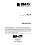
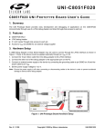
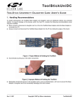
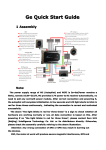
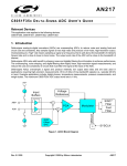
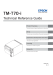
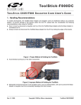
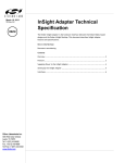
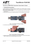
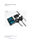
D I G I TA L C O M PA S S - R D
D I G I TA L C O M PA S S R E F E R E N C E D E S I G N K I T U S E R ' S G U I D E
1. Kit Contents
The Digital Compass Reference Design Kit contains the following items:
C8051F350 Digital Compass Reference Design Board
Silicon Laboratories Reference Design CD-ROM. CD content includes the following:
- PC Compass GUI
- Driver installation utility
- Documentation
USB Cable
Digital Compass Reference Design Kit User's Guide (this document)
Two AAA alkaline batteries
2. Introduction
The Digital Compass Reference Design Kit combines the performance of Silicon Laboratories MCU's and the latest
sensors in magnetic and tilt measuring. This reference design offers a high performance and reliable compass
solution while demonstrating the ability to interface sensors directly to an MCU.
3. Quick-Start Guide
The Digital Compass Reference Design Board is a fully functional tilt-compensated digital compass. It can be
powered via batteries for stand-alone operation or via the USB cable when used in conjunction with the GUI. In
order to use the compass immediately:
Install the two AAA alkaline batteries (noting the polarity markings)
Press the ENTER button
The compass will display a traditional direction heading (e.g. N, S, E, W) with absolute information displayed
degrees minutes format. In addition, an arrow and a corresponding 'N' will always point north.
4. General Description
A compass is a navigational instrument for finding direction. It consists of a magnetized pointer, free to align itself
accurately with Earth's magnetic field. It is the oldest instrument for navigation and still is a vital tool even in present
times when GPS exists. Here are the definitions of some terms you will see throughout this user manual:
the azimuth is the angle between magnetic north and the heading direction
declination is the angle between geographic or true north and magnetic north
5. Reference Design Board
The following is a general description of the Digital Compass Reference Design board:
Dimensions: 59 x 88 x 16 mm
Weight: 60 grams
Function buttons: SW1 (MENU) ,SW2 (ENTER) and SW3 (RESET)
LCD display
USB connector
Debug connector
USB and POWER LEDS
Power connector
Slot for 2 x AAA batteries
Rev. 0.1 2/05
Copyright © 2005 by Silicon Laboratories
DIGITAL COMPASS-RD
DIGITAL COMPASS-RD
Note: The USB and power jack are under the LCD display.
Figure 1. Digital Compass Reference Design Board
5.1. USB
The compass can easily be connected to a PC using the USB port. Software is provided to communicate with the
compass through USB. This software displays the same information provided by the compass using a friendly
interface. See Section 8 for details on installing the provided software. Additionally, the USB connection provides
power to the board when connected to a PC.
5.2. LCD
The following is a list of indicators that could be shown on the LCD display. See Figure 2 for a diagram of the LCD
display with all the segments on:
a) Symbols that are used during the calibration process:
1.
CALIBRATION - calibration routine is in progress
2.
ERROR - error encountered during calibration process
3.
TURN - the compass must be turned a full circle
d) Digits and symbols used for azimuth, temperature or inclination display:
1.
5 digits
2.
Degree ( o ) and minute ( ' ) symbols used in azimuth display
3.
X and Y symbols used in inclination display
4.
Decimal point used for temperature display
c) Indications that either temperature, inclination or azimuth is displayed:
1.
When neither of them is on, the azimuth is displayed
2.
When temperature is on, the environment temperature is displayed
3.
When inclination is on, the tilt angles on both X and Y axes is displayed
d) 16 arrows that indicate the North direction relative to the reference point
e) Silicon Laboratories logo
f) 2 digits that indicate the heading or the menu of the compass
2
Rev. 0.1
DIGITAL COMPASS-RD
Figure 2. LCD Indicators
5.3. Buttons
The MENU and ENTER buttons are located on the board to provide access to the compass menu. The following is
a short description of these button functions. See Section 6 for a more detailed description of the operation of the
compass.
1) Press MENU (SW1) to enter the compass menu. Options in menu are:
a) A - displays azimuth information
b) t - displays temperature information
c) I - displays inclination information
d) Ct - calibration of tilt sensor
e) C - calibration of magnetic sensors
Note: During the calibration process the MENU button is used to input angle of declination. See Section 6 for
further details on the calibration process.
2) ENTER (SW2) has the following functions:
a) Enables the option selected in the menu
b) If temperature is displayed, toggles between Celsius and Fahrenheit degrees
c) During calibration process it is used to save angle of declination
Pressing the RESET button will send a reset signal to the C8051F350 device on the board. When this occurs, all
the segments of the LCD display will turn on for a short period of time. After reset, the compass will display the
azimuth mode.
5.4. Power
The compass solution is a low power device. The following are power specifications for the board:
1.
Supply voltage: 3 V, lithium battery, USB or AC-DC adapter (max voltage 12 V)
2.
Supply current: average of 18 mA, stand-by 150 uA
5.5. Power LEDs
Two red power LEDS are provided on the compass board. The LED labeled USB indicates that the board is
receiving power from the USB connection. The LED labeled POWER indicates that the board is receiving power
from an AC-DC adaptor. There is no LED indicator for power provided by batteries.
Rev. 0.1
3
DIGITAL COMPASS-RD
6. Modes Of Operation
6.1. Power Up
When powered from USB, battery or AC-DC adaptor, at power up, all the segments of the LCD display will turn on.
This is an indicator that a normal power up has occurred. After power-up, the compass will display the azimuth mode.
6.2. Azimuth
The default information that is displayed after each reset, power-up or calibration is the azimuth. If you choose
another mode to be displayed and want to return to the azimuth mode, choose menu option "A" and press the
ENTER button to select this option. The following list along with Figure 3 show the details on the azimuth display on
the LCD.
a) The degrees of the azimuth angle
b) The minutes of the azimuth angle
c) The direction of NORTH relative to the reference point
d) Silicon Laboratories logo
e) Heading direction relative to the reference point
Figure 3. LCD Azimuth Mode Display
6.3. Temperature
Another feature of the Digital Compass Reference Design board is measuring and displaying the ambient
temperature. Choose menu option "t" and press the ENTER button to select this option. Temperature can be
displayed either in Celsius degrees or Fahrenheit degrees, as shown in Figure 4. Press the ENTER button to toggle
between temperature displays. Temperature is displayed by default using Fahrenheit degrees.
Figure 4. LCD Temperature Mode Display
4
Rev. 0.1
DIGITAL COMPASS-RD
6.4. Inclination
Choose menu option "I" and press the ENTER button to select this option. Angles of tilt on both X and Y axes will
be displayed on the LCD. Inclination angles can be measured correctly up to 70 degrees on both axes. Beyond this
value the degree displayed will be 70.
Figure 5. LCD Inclination Mode Display
6.5. Tilt Calibration
To calibrate the tilt of the compass, put the board in a horizontal position. Choose menu option "Ct" and press the
ENTER button to select this option. "CALIBRATION" and "INCLINATION" segments will appear during the
calibration process as shown in Figure 6. Do not tilt or move compass during tilt sensor calibration. After tilt
calibration the compass will display the inclination angles. It is recommended that a tilt calibration should be
performed each time tilt angles fluctuate.
Figure 6. LCD Tilt Calibration Mode Display
Rev. 0.1
5
DIGITAL COMPASS-RD
6.6. Calibration
To calibrate the compass, put the board in a horizontal position. Choose menu option "C" and press the ENTER
button to select this option. Use the following steps to perform a calibration of the magnetic compass:
1.
Hold the compass in a perfectly horizontal position. The symbols "CALIBRATION" and "TURN" will be displayed on the
LCD as shown in Figure 7.
Figure 7. LCD Calibration Mode Display
2.
Start rotating the compass, and keeping it as horizontal as possible (Figure 8). Any tilt of the compass during the
rotation will introduce errors in the calibration values. While rotating the compass, the direction arrow on the LCD will
turn around, giving an indication to the user about how fast to rotate the compass. The arrow will make one complete
turn during this step of the calibration procedure. It is recommended that while the arrow makes a complete turn the
compass should be rotated at least 2 complete turns.
Figure 8. Compass Rotation during Calibration
6
Rev. 0.1
DIGITAL COMPASS-RD
3.
Put the compass upside down, again as horizontal as possible, and hold it for a few seconds.
4.
Turn the compass back over to introduce the degree value of the declination angle. Use the MENU button to increment
the value. The display will appear as shown in Figure 9. After the correct value of the declination angle for your region
has been set, press the ENTER button. See Section 7 for an overview of the declination angle.
Figure 9. LCD Declination Angle Degree Display
5.
Use the MENU button to increment the minute value of the declination angle. The display will appear as shown in
Figure 10. After you have finished, press the ENTER button.
Figure 10. LCD Declination Angle Minute Display
The calibration procedure is now finished, and the compass will display the azimuth and the direction. If the
calibration procedure was not successfully completed (e.g. the compass was not rotated 360 degree), the ERROR
symbol will be displayed on the LCD, meaning that the calibration procedure should be repeated for the compass
to work properly.
Rev. 0.1
7
DIGITAL COMPASS-RD
7. Declination Angle
The compass is calibrated at the Silicon Laboratories factory in Austin, Texas but because the angle of declination
varies with respect to geographic position, the compass must be calibrated again for the specific location of use to
achieve maximum accuracy. Table 1 provides this information for several major cities around the world.
Table 1. Angles of Declination for Selected Cities - February 2005
Location
Declination Angle (E)
Austin, Texas
5º 20’
San Francisco, CA
14º 51’
Nuremberg, Germany
1º 23’
London, England
4º 11’
Paris, France
–1º 13’
Tokyo, Japan
–6º 54’
There are a number of resources available on the World Wide Web that compute angles of declination for any
location in the world. A "World Magnetic Model Calculator" is available from both the National Geophysical Data
Center and the British Geological Survey:
http://www.ngdc.noaa.gov/seg/geomag/jsp/struts/calcDeclination
http://www.geomag.bgs.ac.uk/gifs/wmm_calc.html
8. Compass Software
The included CD-ROM contains the Silicon Laboratories Compass Software and additional documentation. This
software allows the user to connect to the compass board and display the information on a PC. The following
sections detail the software installation process and connection options.
8.1. Installation
Use the following steps to install the compass software and USB drivers.
8
1.
Insert the CD-ROM into your PC's CD-ROM drive. An installer will automatically launch, allowing you to install the
compass software. If the installer does not automatically start when you insert the CD-ROM, run
CompassDemoInstall.exe found in the root directory of the CD-ROM.
2.
Follow the prompts to install the Compass Software and the CP210x drivers. These drivers are necessary for the
software to communicate with the board over the USB connection. If using Windows XP, logo testing warnings may
appear. Press the "Continue Anyway" button.
3.
Connect the compass board to the PC with the included USB cable.
4.
When the PC detects the new device it will open a "Found New Hardware Wizard" window.
5.
Press "Next" after selecting the (Recommended) option.
6.
Windows Logo testing warnings may appear. Press the "Continue Anyway" button.
7.
Press "Finish" to finish installing the "CP210x USB Composite Device".
8.
Repeat steps 5, 6 and 7 to install the "CP210x USB Bridge Controller".
Rev. 0.1
DIGITAL COMPASS-RD
8.2. Connection Options
Use the following steps to run the compass software and connect to the board.
1.
Start the compass application by running Compass.exe located by default at "C:\SiLabs\MCU\Demos\C8051F35x".
The application is shown in Figure 11.
Figure 11. Compass Software Startup
2.
To connect to the board, the COM port designated to compass device must be specified. To find the correct COM port,
open the PC's "Device Manager" window. Expand the "Ports (COM & LPT)" section. Find the COM port assigned to
"CP210x USB to UART Bridge Controller". An example is shown in Figure 12.
Figure 12. COM Port in Device Manager
Rev. 0.1
9
DIGITAL COMPASS-RD
3.
Once the COM port has been determined, press the "Select COM Port (COM_)" option in the Compass application.
Enter the correct COM port into the "COM Port Selection" window shown in Figure 13.
Figure 13. COM Port Selection
4.
Press the "Start Communication" button in the Compass application. If the connection is successful, the application will
begin displaying the Direction, Inclination and Temperature calculated by the compass board. The display is shown in
Figure 14.
Figure 14. Compass Software Display
5.
10
To disconnect from the compass board, press the "Stop Communication" button.
Rev. 0.1
'*1'
& &.
& '
5 ( 6 (7
*1'
9
$*1'
'*1'
&
X)
5
5
&
X)
5
.
6&/
6'$
9&&
((3520
8
/ & %
$
$
$
:3
*1'
&'
9
5
.
9
5 .
'*1'
212))
,1
287
1&
9
5
.
5
.
8
6 & %0&;;;7
32:(56833/<
5
.
&
X)
$*1'
86%
& 2
%
'
9
.
X)
&
$*1'
86%
5 &'
73
7RXW
;
;
<
<
=
=
9
&
X)
& '
'*1' '*1' '*1'
'[
'\
$*1'
&
S)
' \
'[
$,1
$,1
$,1
$,1
$,1
$,1
$,1
$,1
&
S)
&
X)
&
S)
0&8
&
S)
'*1'
(17(5
%87721
'*1'
0
&
S)
6:
6 :
5
.
5
.
9
9
&
Q)
'*1'
<
.+]
5
5
.
0(18
%87721
3
3
3
3
9''
'*1'
3
3
/&'32:(56833/<
8
& ) $*1'
7RXW
;
;
<
< = =
'*1'
%
'
9
'*1'
&
X)
7 $ 1 7 $/80
&
X)
9
& X)
5 .
& X)
5 .
/&''5,9(5
&20
&20
9''
9OFG
9OFG
9OFG
9VV
2VF
,1+
&(
&/
',
& 3 & X)
'*1'
9
& 20
& 20
& 20
1&
1&
1&
1&
1&
1&
1&
5(*,1
9%86
'
'
9''
*1'
'&'
8
6
6
6
6
6
6
6
6
6
6
6
6
6
6
6
6
6
6
6
59
5 9
8
&20
&20
&20
6
6
6
6
6
6
6
6
6
6
6
6
6
6
6
6
59
3RZHU
'
86%728$57
6
6
[ 9 0 / $
6
6
6
6
6
6
6
6
8
/&:
6
6
6
6
6
6
6
6
6
6
6
6
6
6
6
6
6
6
6
6
6
6
6
6
6
6
6
6
6
6
6
6
6
1&
5 HG
&
X)
'
5 .
9%86
3:5B;<
3:5B=
3:5B7,/7
6(75(6(7
/ & ' ' , 6 3 / $<
Figure 15. C8051F350-COMPASS Evaluation Board Schematic (Page 1)
6&/
6'$
.
8
) ( 5 , 7 ( % ( $'
&$7+2'(
%7
% $ 7 7 ( 5<
5
5
%
'*1'
&
X)
& 2
$12'(
'
'*1'
9%86
&$7+2'(
$12'(
*1'
5
$12'(
&$7+2'(
$*1'
$9
3&'
567&&.
3
3
3;7$/
3;7$/
95()
95()
3,'$
3,'$2
3
3
3
3
86%
&20
6
6
6
6
6
6
6
6
6
6
6
36
36
36
36
36
36
36
36
6
6
6
6
1&
&76
576
5['
7['
'65
'75
1&
1&
6863(1'
6863(1'
1&
567
5,
&
X)
37
37
W
'*1'
VK
VK
'*1'
8 6 % B 5 ( & ( 3 7 $ &/(%
VK
VK
73
9%86
'
'
*1'
-
$*1'
&2
& 2
3 : 5 B;<
3 : 5 B=
3:5B7,/7
6(75(6(7
&
X)
Rev. 0.1
5
.
DIGITAL COMPASS-RD
9. Schematics
11
& X)
$*1'
8
+ 0 & 9&&
65
287 $
287 $
*1'
*1' %
*1' %
65
8
+ 0 & 9&&
*1'
*1'
*1'
65
$*1'
+21(<:(//=
$;,66(1625
&
X)
& X)
&
X)
5 .
5 5
$*1'
& X)
&
X)
5
.
&
X)
5
.
$*1'
&
X )
& X)
5 .
'*1'
9GD
9GG
*1'
& X)
7RXW
'RXW[
'RXW\
8
0 ; ' 8/
7,/76(1625
$*1'
&
X )
5
.
'*1'
=
=
;
;
<
<
=
=
;
;
<
<
$*1'
&
X )
4
6L
4
6L
5
5
&
X)
5 5
&
X)
6(75(6(7&LUFXLW
& X)
$*1'
$*1'
9
287
'*1'
&
X)
$ *1'
6(75(6(7
7RXW
'[
'\
& X)
& X)
287
Figure 16. C8051F350-COMPASS Evaluation Board Schematic (Page 2)
&
X)
287$
287$
287%
287%
65
5 .
6 F N 9UHI
+21(<:(//; <
$;,66(1625
Rev. 0.1
1&
1&
*1'
*1'
,1
4
6L
2Q2II
,1
8
0 & 8
0 & 2Q2II
& X)
12
5 .
9
&
X)
&
X)
9
&
X)
9
3:5B7,/7
3:5B=
$*1'
9
3 : 5 B;<
$*1'
9
DIGITAL COMPASS-RD
3
3 +21(-$&.
Rev. 0.1
&
X)
&
X ) 9
%
'
5 .
&
X)
&$7+2'(
(Q
,1
8
/ & '
'(%8*
-
% R [ SLQ
287
9%%
&
X)
& X 7 9
3RZHU
'*1'B%%
'
5HG
5 5
'*1'B%%
5 5
Figure 17. C8051F350-COMPASS Evaluation Board Schematic (Page 3)
'*1'B%%
6 :
5(6(7
%87721
'*1'B%%
5 5
$12'(
*1'
*1'
*1'
*1'
1&
5 5
73
9%%
'*1'B%%
&
X)
%
'
9%%
$12'(
&$7+2'(
9SV
&&.
& '
5 ( 6 (7
*1'
9
DIGITAL COMPASS-RD
13
DIGITAL COMPASS-RD
CONTACT INFORMATION
Silicon Laboratories Inc.
4635 Boston Lane
Austin, TX 78735
Tel: 1+(512) 416-8500
Fax: 1+(512) 416-9669
Toll Free: 1+(877) 444-3032
Email: [email protected]
Internet: www.silabs.com
The information in this document is believed to be accurate in all respects at the time of publication but is subject to change without notice.
Silicon Laboratories assumes no responsibility for errors and omissions, and disclaims responsibility for any consequences resulting from
the use of information included herein. Additionally, Silicon Laboratories assumes no responsibility for the functioning of undescribed features
or parameters. Silicon Laboratories reserves the right to make changes without further notice. Silicon Laboratories makes no warranty, representation or guarantee regarding the suitability of its products for any particular purpose, nor does Silicon Laboratories assume any liability
arising out of the application or use of any product or circuit, and specifically disclaims any and all liability, including without limitation consequential or incidental damages. Silicon Laboratories products are not designed, intended, or authorized for use in applications intended to
support or sustain life, or for any other application in which the failure of the Silicon Laboratories product could create a situation where personal injury or death may occur. Should Buyer purchase or use Silicon Laboratories products for any such unintended or unauthorized application, Buyer shall indemnify and hold Silicon Laboratories harmless against all claims and damages.
Silicon Laboratories and Silicon Labs are trademarks of Silicon Laboratories Inc.
Other products or brandnames mentioned herein are trademarks or registered trademarks of their respective holders.
14
Rev. 0.1