1
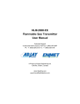
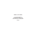
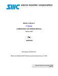
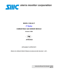
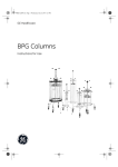
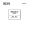
MODEL 5000
SENTRY
GAS MONITORING SYSTEM
Version 6
Sensors Service
APPLICABILITY & EFFECTIVITY
Effective for all Sentry systems manufactured after September 1, 1995.
Instruction Manual Part Number T12001-A1
Sierra Monitor Corporation
1991 Tarob Court, Milpitas, CA 95035
(408) 262-6611
Applicability & Effectivity
SMC sierra monitor corporation
7.5
Sentry Instruction Manual - Version 6
COMBUSTIBLE GAS SENSOR MODULE
(5100-02)
7.5.1 DESCRIPTION
The Combustible Gas Module includes the sensor
and electronic assembly installed in an explosion
proof housing. The sensor screws into one hub of
the enclosure and plugs into the bottom
electronics card via a six pin connector. Cabling
to the controller connects to a three pin spring
loaded terminal strip.
7.5.2 TROUBLE ANALYSIS
Electrical adjustment, or replacement of the
sensor will be necessary under the following
conditions:
•
Controller displays the following error
messages:
CHK BRIDGE VOLT
SENSOR FAILURE
LOW SENSITIVITY
•
False readings or alarms are received
due to sensor inaccuracy.
Warning: : During sensor adjustments the
concentration reading on the controller will be
inaccurate and alarm level concentrations may be
displayed. If false activation of the alarm relays
will cause a problem disconnect the relay wiring
prior to adjustment or turn the module off using the
CHANGE MODULE mode.
NOTE
Although all the necessary data can be collected with a
voltmeter at the sensor module, some helpful information
can be displayed or printed. See diagnostic codes 0004
and 0008 in Appendix C.
Figure 7-6
Cover Plate - Combustible Gas Module
Comparing to the "GND" (ground) test point measure
"BRIDGE VOL" (bridge voltage) and adjust to 2.00 VDC
using "BRIDGE ADJ" potentiometer. Turn counterclockwise to increase.
7.5.3.2 ZERO ADJUSTMENT
7.5.3 ADJUSTMENT PROCEDURE
Comparing to ground measure SIGNAL OUT and adjust to
0.18 VDC by turning ZERO ADJ potentiometer. Turn
counter clock-wise to increase.
Prior to reading voltages and making adjustments perform
a visual inspection to confirm that there are no physical
problems such as water in the electronics enclosure,
wiring damage or corrosion.
7.5.3.3 SPAN ADJUSTMENT
Use Figure 7-6 to locate test points during the following
procedures:
Caution: The area must be free of flammable vapors or
gases during any adjustments or maintenance procedures.
7.5.3.1 BRIDGE VOLTAGE ADJUSTMENT
Confirm that no combustible gas is present and remove
sensor module cover.
SERVICE
Page: 69
1.
Determine the concentration of the calibration
gas (CG) in % LEL.
2.
Use the following formula to determine the
response to the calibration gas at SIGNAL OUT.
Voltage (Signal Out) = (CG+12)/60
For Example:
If CG = 50% L.E.L
Signal Out = (50+12)/60
= 1.03 volts
SMC sierra monitor corporation
3.
4.
5.
Sentry Instruction Manual - Version 6
Using a Sierra Monitor Model 1200-26 Gas
Calibrator with a Sierra Monitor Model 535800 calibration adapter, or Model 5360 Gas
Delivery Fitting. Apply the calibration gas at a
flow rate of 100 cc/min. until the signal out
voltage stops changing (approx. 2 minutes).
Then adjust span adj. potentiometer to the
calculated value.
PIN
Remove the calibration gas and wait for the
voltage to drop. If the voltage is below 0.30
VDC the procedure is complete. If the voltage
is above 0.30 VDC repeat the zero and span
adjustments.
Calibrate the sensor using the instruction
manual procedure.
• A LOW SENSITIVITY message during
calibration indicates one of the two
conditions for a combustible sensor:
• The zero gas voltage must be less than
.3 volts.
• The new span change (span voltage less
zero voltage) must exceed 30% of the
calculated span change.
For Example:
Zero gas voltage = .20 VDC
Span voltage = .43 VDC
Span change is .43-.2 = .23 VDC
As the calculated span value (from
step 5 above) is 1.03, the calculated
span change is: 1.03-.2 = .87
By calculation: 30% of .87 = .26
The new span change (.23) is less than
30% of the calculated span change so a
LOW SENSITIVITY message will be
displayed.
FUNCTION
WIRE COLOR
1
DETECTOR
WHITE
2
COMPENSATOR
BROWN
3
CALIB. SW.
RED
4
DETECTOR
BLACK
5
DRAIN
6
CALIB. SW.
BARE
GREEN
Table 7-5
Combustible Gas Sensor
Wiring Pin Out
1.
Detector element resistance should be between 1.5 to
2 ohms.
2.
Compensator element resistance should be between
1.5 to 2 ohms.
3.
Calibration switch should be open in normal
operation and should close when the calibration
magnet is applied.
If the sensor fails any of these tests it should be replaced.
If the sensor passes these tests the electronics are suspect
and BOTH the sensor and electronics should be replaced.
(The electronics and sensor which are removed should be
returned to the factory for evaluation).
When a new sensor is installed the following actions must
be taken:
The LOW SENSITIVITY calculation is made to insure that
the calibration does not adjust the electronics so that the
"gain" is large enough to cause false alarms due to minor
drift or due to minimal electronic noise.
7.5.4 SENSOR REPLACEMENT
If any of the above adjustments cannot be completed
successfully the sensor and/or electronics will require
replacement. To check the sensor unplug it from the
electronics and remove from the housing so that
continuity and resistance tests can be made. Table 7-4
provides the pin out for the sensor assembly.
SERVICE
Page: 70
•
Make
the
bridge
voltage
adjustment
immediately to avoid over-voltage damage to
the sensor.
•
Use diagnostic code 0020 to establish nominal
value calibration.
•
Allow 24 hours for full stabilization of the
sensor, recheck the zero and span adjustments
and calibrate the sensor module.
SMC sierra monitor corporation
Sentry Instruction Manual - Version 6
7.5.5 COMBUSTIBLE GAS SCALING FACTORS
For combustible gas monitoring, a calibration standard of Methane or Propane my be used in conjunction with scaling
factors to cause Sentry concentration display and alarm function in %LEL scale of another gas as follows:
GAS
Acetaldehyde
Acetic Acid
Acetic Anhydride
Acetone
Acetylene
Alkyl Alcohol
Ammonia
n-Amyl Alcohol
Aniline
Benzene
Biphenyl
1,3-Butadiene
n-Butane
iso-Butane
Butene-1
cis-Butene-2
trans-Butene-2
n-Butyl Alcohol
iso-Butyl Alcohol
tert-Butyl-Alcohol
n-Butyl Benzene
iso-Butyl Benzene
n-Butyric Acid
Carbon Disulfide
Carbon Monoxide
Carbon Oxysulphide
Chlorobenzene
Cyanogen
Cyclohexane
Cyclopropane
n-Decane
Diethylamine
Dimethylamine
2,3-Dimethylpentane
2,3-Dimethylpropane
Dimethylsulphide
1,4-Dioxane
Epichlorohydrin
Ethane
Ethyl Acetate
Ethyl Alcohol
Ethylamine
Ethyl Benzene
Ethyl Bromide
Ethyl Chloride
Ethylcyclopentane
Ethylene
Ethylenedichloride
Ethyleneoxide
METHANE
FACTOR
60
54
46
52
57
51
126
33
39
41
25
56
58
52
45
48
51
34
53
74
31
32
38
18
75
93
34
89
41
62
33
49
58
40
40
43
45
45
68
51
73
53
36
91
57
40
71
66
52
PROPANE
FACTOR
109
98
83
94
103
92
229
59
71
74
45
101
106
94
82
88
92
62
96
134
57
58
69
32
137
169
62
162
74
113
59
88
105
72
72
79
81
82
123
93
132
95
65
165
103
72
128
120
94
GAS
Diethyl Ether
Dimethoxyethane
Dimethyl Ether
Dimethylformamide
Ethyl Formate
Ethylmercaptan
n-Heptane
n-Hexane
Hydrazine
Hydrogencyanide
Hydrogen
Hydrogen Sulfide
Methane
Methyl Actetate
Methyl Alcohol
Methylamine
Methyl Bromide
Methyl Chloride
Methylcyclohexane
Methylenedichloride
Methylethylether
Methylethylketone
Methyl Formate
Methylmercaptan
Methylpropionate
Methyl n-propylketone
Napthalene
Nitromethane
n-Nonane
n-Octane
n-Pentane
i-Pentane
Propane
n-Propyl Alcohol
n-Propylamine
n-Propylchloride
Propylene
Propyleneoxide
iso-Propylether
Propyne
Toluene
Triethylamine
Trimethylamine
Vinylethylether
o-Xylene
m-Xylene
p-Xylene
JP-4 (Jet Fuel)
METHANE
FACTOR
46
42
63
46
44
56
39
37
45
48
77
41
100
50
86
77
90
102
44
93
44
41
67
61
51
40
34
34
31
37
46
46
55
47
48
50
52
46
44
42
40
40
48
42
36
39
39
41
PROPANE
FACTOR
84
75
113
83
80
102
70
67
82
86
139
74
181
90
156
140
162
186
80
168
80
75
121
110
93
73
62
62
57
68
83
84
100
85
88
90
93
83
79
75
73
72
88
76
65
71
71
73
NOTES:
1.
Scaling factors are not FMRC approved.
2.
Base data source: EEV sensor specification catalog. (EEV claims some data is the result of specific tests, other
data is empirically derived.)
SERVICE
Page: 71
SMC sierra monitor corporation
Sentry Instruction Manual - Version 6
7.6 OXYGEN MODULE (5100-03)
7.6.1 DESCRIPTION
The Oxygen Module includes the electronic
assembly installed in an explosion proof housing
and the electrochemical sensor connected to one
hub of the enclosure. Cabling from the controller
connects to a three pin spring loaded terminal
strip.
7.6.2 TROUBLE ANALYSIS
Electrical adjustment, or replacement of the
sensor will be necessary under the following
conditions:
•
Controller displays the following error
messages:
CHANGE SENSOR
SENSOR FAILURE
REPLACE SENSOR
•
False readings or alarms are received due to
sensor inaccuracy.
Warning: During
sensor
adjustments
the
concentration reading on the controller will be
inaccurate and alarm level concentrations may be
displayed. If false activation of the alarm relays
will cause a problem disconnect the relay wiring
prior to adjustment or turn the module off using
the "Change Module" mode.
Figure 7-7
Cover Plate - Oxygen Module
7.6.4 SENSOR REPLACEMENT
NOTE
Although all the necessary data can be collected with a
voltmeter at the sensor module, some helpful information
can be displayed on the controller or printed. See
diagnostic codes 0004 and 0008 in Appendix C.
The oxygen sensor should be replaced when it can no
longer be calibrated correctly or when the signal output
drops to zero. Generally this is every twelve to eighteen
months. The Sentry clock keeps track of the age of the
sensor if it is correctly initialized in the "change module"
mode.
7.6.3 ADJUSTMENT PROCEDURE
Prior to reading voltages and making adjustments perform
a visual inspection to confirm that there are no physical
problems such as water in the electronics enclosure,
wiring damage or corrosion.
Use Figure 7-7 to locate test points during the following
procedures.
7.6.3.1 SIGNAL ADJUSTMENT
It is unlikely that any electrical adjustment will be
required except when a new sensor is installed.
To make the electrical adjustment connect a voltmeter to
SIGNAL OUT (pos) and GND (ground) and use
SENSITIVITY ADJ potentiometer to set the voltage equal to
1/10 of the actual oxygen concentration. In clean air the
concentration is 20.9% so the voltage should be set at
2.09 VDC.
When a new sensor is installed use the CHANGE MODULE
menu selection to answer yes to the "new sensor?"
question. After nine months the CHANGE SENSOR
message will be displayed to warn that a new sensor
should be installed.
The SENSOR FAILURE message for Oxygen sensors does
not indicate a specific failure of the sensor but indicates
that the sensor is not correctly connected to the
electronics. If this message appears check that the sensor
harness is correctly installed to the connector on the
bottom electronics board.
When sensor replacement is required, open the cover of
the sensor module, remove the transmitter and disconnect
the sensor wiring harness from the back of the transmitter.
SERVICE
Page: 72
SMC sierra monitor corporation
Sentry Instruction Manual - Version 6
Unscrew the old sensor from the conduit hub, screw in
the new sensor and connect the wiring harness to the
transmitter electronics. Replace the transmitter into the
enclosure, make signal adjustments as described above,
and replace the enclosure cover.
After the sensor is installed:
•
Update "new sensor" status in the change
module mode.
•
Allow one hour of stabilization of the new
sensor.
•
Make the electrical sensitivity adjustment as
described above.
•
Calibrate the sensor module.
SERVICE
Page: 73
SMC sierra monitor corporation
Sentry Instruction Manual - Version 6
7.7 CARBON MONOXIDE MODULE (5100-04)
7.7.1 DESCRIPTION
The Carbon Monoxide Module includes the
sensor and electronic assembly installed in an
explosion proof housing.
The sensor screws into one hub of the enclosure
and plugs into the bottom electronics card via a
six pin connector. Cabling from the controller
connects to a three pin spring loaded terminal
strip.
7.7.2 TROUBLE ANALYSIS
Electrical adjustment, or replacement of the
sensor will be necessary under the following
conditions:
•
Controller displays the following error
messages
SENSOR FAILURE
LOW SENSITIVITY
•
False readings or alarms are received
due to sensor inaccuracy.
Warning: During
sensor
adjustments
the
concentration reading on the controller will be
inaccurate and alarm level concentrations may be
displayed. If false activation of the alarm relays
will cause a problem disconnect the relay wiring
prior to adjustment or turn the module off using the
"Change Module" mode.
Note
Although all the necessary data can be collected with a
voltmeter at the sensor module, some helpful information
can be displayed on the controller or printed. See
diagnostic codes 0004 and 0008 in Appendix C.
Figure 7-8
Cover Plate - Carbon Monoxide Module
•
1 ppm CO = 0.004 VDC.
•
100 ppm CO = 0.40 VDC.
•
250 ppm CO = 1.00 VDC.
7.7.3.2 SENSOR REPLACEMENT
7.7.3 ADJUSTMENT PROCEDURE
Prior to reading voltages and making adjustments perform
a visual inspection to confirm that there are no physical
problems such as water in the electronics enclosure,
wiring damage or corrosion.
Use Figure 7-8 to locate test points during the following
procedures.
The carbon monoxide sensor should be replaced when it
can no longer be calibrated correctly. Generally this is
every twenty four to thirty months.
The "SENSOR FAILURE" message for Carbon
Monoxide sensors does not indicate a specific failure of
the sensor but indicates that the sensor is not correctly
connected to the electronics. If this message appears
check that the sensor harness is correctly installed to the
connector on the bottom electronics board.
7.7.3.1 SIGNAL ADJUSTMENT
It is unlikely that any electrical adjustment will be
required except when a new sensor is installed.
To make the electrical adjustment connect a voltmeter to
SIGNAL OUT (pos) and GND (ground) and use
SENSITIVITY ADJ potentiometer to adjust the voltage
based on the following:
SERVICE
Page: 74
SMC sierra monitor corporation
Sentry Instruction Manual - Version 6
If sensor replacement is necessary remove the electronics
from the housing and unplug the old sensor from the
bottom board, remove it from the enclosure hub and
reverse the procedure to install the new sensor.
After the sensor is installed:
•
Allow one hour of stabilization of the new
sensor.
•
Make the electrical sensitivity adjustment as
described above.
•
Calibrate the sensor using the instruction
manual procedure.
SERVICE
Page: 75
SMC sierra monitor corporation
Sentry Instruction Manual - Version 6
7.8 HYDROGEN SULFIDE MODULE (5100-05)
7.8.1 DESCRIPTION
Model 5100-05 Hydrogen Sulfide Sensor Module
includes a sensor assembly and electronic
assembly installed in an explosion proof housing.
The sensor assembly includes a reuseable housing
and disposable electrochemical sensor.
The
assembly screws into one hub of the sensor
module enclosure and plugs into the bottom
electronics card via a six pin connector.
Cabling from the controller connects to a three
pin spring loaded terminal strip on the electronics
assembly.
7.8.2 TROUBLE ANALYSIS
Electrical adjustment, or replacement of the
sensor will be necessary under the following
conditions:
•
Controller displays the following error
messages
SENSOR FAILURE
LOW SENSITIVITY
•
Figure 7-9
Cover Plate - Hydrogen Sulfide Module
False readings or alarms are received
due to sensor inaccuracy.
Warning:
During sensor adjustments the
concentration reading on the controller will be
inaccurate and alarm level concentrations may be
displayed. If false activation of the alarm relays will
cause a problem disconnect the relay wiring prior to
adjustment or turn the module off using the "Change
Module" mode.
NOTE
Although all the necessary data can be collected with a
voltmeter at the sensor module, some helpful information
can be displayed on the controller or printed. See
diagnostic codes 0004 and 0008 in Appendix C.
To make the electrical adjustment connect a voltmeter to
SIGNAL OUT (pos) and GND (ground) and use SPAN ADJ
potentiometer to adjust the voltage based on the
following:
•
1 ppm H2S = 0.02 VDC.
•
100 ppm H2S = 2.00 VDC.
7.8.3.2 SENSOR REPLACEMENT
The Hydrogen Sulfide sensor should be replaced when it
can no longer be calibrated correctly. Generally this is
every twenty four to thirty months.
7.8.3 ADJUSTMENT PROCEDURE
Prior to reading voltages and making adjustments perform
a visual inspection to confirm that there are no physical
problems such as water in the electronics enclosure,
wiring damage or corrosion.
Use Figure 7-9 to locate test points during the following
procedures.
7.8.3.1 SIGNAL ADJUSTMENT
It is unlikely that any electrical adjustment will be
required except when a new sensor is installed.
The SENSOR FAILURE message for Hydrogen Sulfide
sensors does not indicate a specific failure of the sensor
but indicates that the sensor is not correctly connected to
the electronics. If this message appears check that the
sensor harness is correctly installed to the connector on
the bottom electronics board.
The gas sensor which is located inside the sensor
assembly housing can be replaced without replacement of
the housing. To replace the sensor:
SERVICE
Page: 76
SMC sierra monitor corporation
Sentry Instruction Manual - Version 6
1.
Confirm that system power has been
removed.
2. Remove the transmitter electronics board
from the main housing and unplug the
sensor harness from the transmitter
electronics.
3. Unscrew the sensor housing from the
bottom of the enclosure
4. Hold the sensor assembly so that the
harness faces down and the sensor faces
up. Unscrew and remove the round
section of the housing from the hex
section. Be careful not to lose the spacer
washer which will be sitting on top of the
exposed sensor.
5. Carefully pull the old sensor straight up
from the socket.
6. Orient the new sensor so that the sensor
pin labeled “C” faces the socket labeled
“C” which is on the far side of the board
from the vertical reed switch. The reed
switch will slide into a hole on the side of
the new sensor. Press the new sensor’s
pins into the three sockets.
7. Carefully replace the cover on the sensor
assembly including the spacer washer.
8. Install the sensor assembly into the enclosure and
tighten firmly.
9. Reconnect the sensor harness to the transmitter,
install the transmitter into the housing and restore
power.
10. Allow one hour for the sensor to stabilize prior to
recalibration.
11. Recalibrate the sensor module.
Figure 7-10
Hydrogen Sulfide Transmitter Component Locator
7.8.3.3 SENSOR OUTPUT ADJUSTMENT
The following procedure is to be used when, during
normal calibration of a new sensor, the span voltage
cannot be adjusted to a high enough level.
1. Adjust the span potentiometer so that it is
approximately mid range.
(Twenty turns
clockwise and tens turns counter-clockwise).
2. Remove system power and remove both the
transmitter and the sensor assembly from the
enclosure. Remove the sensor assembly cover so
that the sensor is visible.
3. Plug the sensor harness into the transmitter
assembly and check that no components are
touching the enclosure. Restore power and allow
a minimum of 30 minutes for stabilization before
adjustment.
SERVICE
Page: 77
4.
Connect a DVM across TP10 and GT1 on the
transmitter assembly. Figure 7-10
5. Locate the gain potentiometer which is on the
sensor electronics directly behind one of the holes
in the sensor body.
The potentiometer is
accessible by inserting a jewelers screwdriver
through the hole in the sensor.
6. Determine the correct value to be read at TP10
based on the following formula:
VTP10 = 2(C/R) , where C = concentration of span gas,
and R = range of detection (100 PPM).
7. Apply span gas. Adjust the gain potentiometer
until TP10 = correct value as described above.
To increase voltage at TP10 turn the gain
potentiometer counter clockwise.
8. Remove system power and re-install the sensor
and transmitter in the enclosure. Restore power
and calibrate.
SMC sierra monitor corporation
Sentry Instruction Manual - Version 6
7.9 TOXIC GAS SENSOR MODULE
7.9.1 DESCRIPTION
Toxic Gas Sensor Modules include the following
models and default ranges:
5100-06
5100-07
5100-12
5100-13
Chlorine -10 PPM
Hydrogen - 2000 PPM
Nitrogen Dioxide - 20 PPM
Carbon Monoxide, High Range 1,000 PPM
5100-10 Sulfur Dioxide - 100 PPM
5100-16 Carbon Monoxide, H2 Tolerant 2,000 PPM
5100-19 Nitric Oxide - 20 PPM
5100-21 Hydrogen Chloride - 20 PPM
5100-22 Hydrogen Cyanide - 20 PPM
5100-27 Ethylene Oxide - 20 PPM
The Toxic Sensor Module includes a sensor
assembly and electronic assembly installed in an
explosion proof housing.
The sensor assembly includes a reuseable housing
and disposable electrochemical sensor.
The
assembly screws into one hub of the sensor
module enclosure and plugs into the bottom
electronics card via a six pin connector.
Figure 7-11
Cover Plate - Toxic Gas Module
7.9.3 ADJUSTMENT PROCEDURE
Cabling from the controller connects to a three pin spring
loaded terminal strip on the electronics assembly.
7.9.2 TROUBLE ANALYSIS
Electrical adjustment, or replacement of the sensor will be
necessary under the following conditions:
•
Controller
messages
displays
the
following
Use Figure 7-11 to locate test points during the following
procedures.
error
7.9.3.1 SIGNAL ADJUSTMENT
SENSOR FAILURE
LOW SENSITIVITY
•
Prior to reading voltages and making adjustments perform
a visual inspection to confirm that there are no physical
problems such as water in the electronics enclosure,
wiring damage or corrosion.
False readings or alarms are received due to
sensor inaccuracy.
Warning: During sensor adjustments the concentration
reading on the controller will be inaccurate and alarm
level concentrations may be displayed. If false activation
of the alarm relays will cause a problem disconnect the
relay wiring prior to adjustment or turn the module off
using the "Change Module" mode.
It is unlikely that any electrical adjustment will be
required except when a new sensor is installed.
To make the electrical adjustment connect a voltmeter to
SIGNAL OUT (pos) and GND (ground) and use SPAN ADJ
potentiometer to adjust the voltage based on the
following:
•
•
1% of full scale = 0.02 VDC.
100% of full scale = 2.00 VDC.
7.9.3.2 SENSOR REPLACEMENT
NOTE
Although all the necessary data can be collected with a
voltmeter at the sensor module, some helpful information
can be displayed on the controller or printed. See
diagnostic codes 0004 and 0008 in Appendix C.
The toxic gas sensor should be replaced when it can no
longer be calibrated correctly. Generally this is every
twenty four to thirty months.
SERVICE
Page: 78
SMC sierra monitor corporation
Sentry Instruction Manual - Version 6
The SENSOR FAILURE message for toxic gas
sensors does not indicate a specific failure of the
sensor but indicates that the sensor is not correctly
connected to the electronics. If this message
appears check that the sensor harness is correctly
installed to the connector on the bottom
electronics board.
The gas sensor which is located inside the sensor
assembly housing can be replaced without
replacement of the housing. To replace the
sensor:
1.
Confirm that system power has been
removed.
2. Remove the transmitter electronics board
from the main housing and unplug the
sensor harness from the transmitter
electronics.
3. Unscrew the sensor housing from the
bottom of the enclosure
4. Hold the sensor assembly so that the
harness faces down and the sensor faces
up. Unscrew and remove the round
section of the housing from the hex
section. Be careful not to lose the spacer
washer which will be sitting on top of the
exposed sensor.
5. Carefully pull the old sensor straight up from the
socket.
6. Orient the new sensor so that the sensor pin
labeled “C” faces the socket labeled “C” which is
on the far side of the board from the vertical reed
switch. The reed switch will slide into a hole on
the side of the new sensor. Press the new
sensor’s pins into the three sockets.
7. Carefully replace the cover on the sensor
assembly including the spacer washer.
8. Install the sensor assembly into the enclosure and
tighten firmly.
9. Reconnect the sensor harness to the transmitter,
install the transmitter into the housing and restore
power.
10. Allow one hour for the sensor to stabilize prior to
recalibration.
11. Recalibrate the sensor module.
Figure 7-12
Toxic Gas Transmitter Component Locator
7.9.3.3 SENSOR OUTPUT ADJUSTMENT
The following procedure is to be used when, during
normal calibration of a new sensor, the span voltage
cannot be adjusted to a high enough level.
SERVICE
Page: 79
1.
Adjust the span potentiometer so that it is
approximately mid range.
(Twenty turns
clockwise and tens turns counter-clockwise).
2. Remove system power and remove both the
transmitter and the sensor assembly from the
enclosure. Remove the sensor assembly cover so
that the sensor is visible.
3. Plug the sensor harness into the transmitter
assembly and check that no components are
touching the enclosure. Restore power and allow
a minimum of 30 minutes for stabilization before
adjustment.
4. Connect a DVM across TP10 and GT1 on the
transmitter assembly. Figure 7-12
5. Locate the gain potentiometer which is on the
sensor electronics directly behind one of the holes
in the sensor body.
The potentiometer is
accessible by inserting a jewelers screwdriver
through the hole in the sensor.
6. Determine the correct value to be read at TP10
based on the following formula:
VTP10 = 2(C/R) , where C = concentration of span gas,
and R = range of detection (100 PPM). The value
is negative for all models except 5100-06, and
5100-19.
SMC sierra monitor corporation
7.
8.
Sentry Instruction Manual - Version 6
Apply span gas. Adjust the gain potentiometer
until TP10 = correct value as described above.
To increase voltage at TP10 turn the gain
potentiometer counter clockwise.
Remove system power and re-install the sensor
and transmitter in the enclosure. Restore power
and calibrate.
SERVICE
Page: 80
SMC sierra monitor corporation
Sentry Instruction Manual - Version 6
7.10 AMMONIA SENSOR MODULE (5100-25)
7.10.1 DESCRIPTION
The Ammonia Sensor Module includes a sensor
assembly and electronic assembly installed in an
explosion proof housing.
The sensor assembly includes a rechargeable
electrochemical sensor. The assembly screws into
one hub of the sensor module enclosure and plugs
into the bottom electronics card via a six pin
connector.
Cabling from the controller connects to a three
pin spring loaded terminal strip on the electronics
assembly.
7.10.2 TROUBLE ANALYSIS
Electrical adjustment, recharge, or replacement of
the sensor will be necessary under the following
conditions:
•
Controller displays the following error
messages
SENSOR FAILURE
LOW SENSITIVITY
•
Figure 7-13
Cover Plate - Ammonia Module
False readings or alarms are received
due to sensor inaccuracy.
Warning:
During sensor adjustments the
concentration reading on the controller will be
inaccurate and alarm level concentrations may be
displayed. If false activation of the alarm relays will
cause a problem disconnect the relay wiring prior to
adjustment or turn the module off using the "Change
Module" mode.
NOTE
Although all the necessary data can be collected with a
voltmeter at the sensor module, some helpful information
can be displayed on the controller or printed. See
diagnostic codes 0004 and 0008 in Appendix C.
To make the electrical adjustment connect a voltmeter to
SIGNAL OUT (pos) and GND (ground) and use SPAN ADJ
potentiometer to adjust the voltage based on the
following:
•
1% of full scale = 0.02 VDC.
•
100% of full scale = 2.00 VDC.
7.10.3.2 SENSOR RECHARGE
7.10.3 ADJUSTMENT PROCEDURE
The Ammonia sensor can be recharged by removing it
from service, draining electrolyte, cleaning electrodes and
replacing the electrolyte and membrane.
Prior to reading voltages and making adjustments perform
a visual inspection to confirm that there are no physical
problems such as water in the electronics enclosure,
wiring damage or corrosion.
Step by step instructions for sensor recharge are supplied
with the recharge kit.
Use Figure 7-13 to locate test points during the following
procedures.
7.10.3.3 SENSOR REPLACEMENT
The Ammonia sensor assembly should be replaced when
it can no longer be recharged and calibrated correctly.
7.10.3.1 SIGNAL ADJUSTMENT
It is unlikely that any electrical adjustment will be
required except when a new sensor is installed.
SERVICE
Page: 81
SMC sierra monitor corporation
Sentry Instruction Manual - Version 6
The SENSOR FAILURE message for ammonia sensors does
not indicate a specific failure of the sensor but indicates
that the sensor is not correctly connected to the
electronics. If this message appears check that the sensor
harness is correctly installed to the connector on the
bottom electronics board.
To replace the sensor assembly:
1.
2.
3.
4.
5.
6.
7.
Confirm that system power has been removed.
Remove the transmitter electronics board from
the main housing and unplug the sensor harness
from the transmitter electronics.
Unscrew the sensor housing from the bottom of
the enclosure
Install the new sensor assembly into the enclosure
and tighten firmly.
Reconnect the sensor harness to the transmitter,
install the transmitter into the housing and restore
power.
Allow one hour for the sensor to stabilize prior to
recalibration.
Recalibrate the sensor module.
SERVICE
Page: 82