1
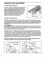
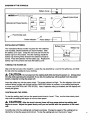
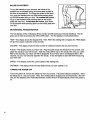
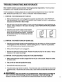
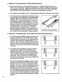
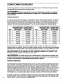
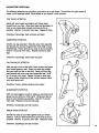
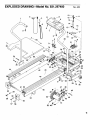
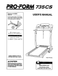
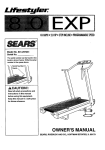
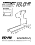
• O.W.O MPH
Jk 1.25HORSEPOWER
• STEP CONTROL MANUAL INCLINE
DC MOTOR
A MADEIN
THE U.S.A.
OWNER'S MANUAL
Model No. 831.297400
Serial No.
The serial number can be found in the
location shown below. Write the serial
number in the space above.
Number
Decal
CAUTION!:
Read all safety precautions
and instructions
in this
manual before using this
equipment. Keep this
manual in a safe place for
future reference.
SEARS, ROEBUCK AND CO., HOFFMAN ESTATES, IL 60179
• 0-8.0 MPN
• 1.25 HORSEPOWER DC MOTOR
• STEP CONTROL MANUAL INCLINE • MADE IN THE U.S.A.
TABLE OF CONTENTS
WARRANTY .......................................................................
IMPORTANT
SAFETY PRECAUTIONS
...........................
BEFORE YOU BEGIN ..............................................................
ASSEMBLY .......................................................................
OPERATION
AND ADJUSTMENT
.....................................................
TROUBLE-SHOOTING
AND STORAGE
................................................
CONDITIONING
GUIDELINES
......................................................
PART LIST .......................................................................
EXPLODED
DRAWING .............................................................
ORDERING
REPLACEMENT
PARTS ..........................................
......................
2
3
4
5
6
9
12
14
15
Back Cover
iiii iii
iiii
FULL 90 DAY WARRANTY
For 90 days from the date of purchase, when proper assembly and maintenance procedures
detailed in the Owner's Manual are followed, SEARS will, free of charge, repair or replace and
install a replacement part for any defective part, when this treadmill is used in a normal manner.
This warranty does not apply when this treadmill is used for commercial
or rental purposes.
SERVICE IS AVAILABLE SIMPLY BY CONTACTING YOUR NEAREST SEARS SERVICE
CENTER/DEPARTMENT
IN THE UNITED STATES.
This warranty gives you specific legal rights, and you may also have other rights which vary
from state to state.
SEARS, ROEBUCK AND CO., DEPT. 817WA,
3333 BEVERLY ROAD, HOFFMAN ESTATES, IL 60179
WARNING:
2
Before beginning this or any exercise program, consult your physlclan.
This Is especially Important for persons over the age of 35 or persons wlth pre4xlstlng health
problems. Read all Instructlons before using. SEARS assumes no responslblllty for personal
Injury or property damage sustained by or through the use of thls product.
IMPORTANT SAFETY PRECAUTIONS
WARNING:
the followlng
To reduce
Important
the risk of burns,
safety
precautions
fire, electric
and Informatlon
shock
or injury to persons,
before operatlng
read
the treadmlll.
1. Position the treadmill on a level surface, wlth at least 8 feat of clearance behlnd the treadmill. Do not place the treadmill near water, outdoors or on any surface that blocks an air
openlng.
Istered.
.
Do not operate
where
aerosol
products
are used or where oxygen
Is being
admln-
When connecting
the power cord (see OPERATION
AND ADJUSTMENT
in thls manual),
plug the power cord directly Into a grounded
clrcuit capable of carrying 12 or more amps.
No other appllance should be on the same clrcult. Keep the power cord away from heated
surfaces.
If an extension cord is needed, use only a 14-gauge general-purpose
cord of five
feet or less In length with a three-wlre
conductor.
3. Never move the walking belt while the power Is turned off. Do not operate the treadmill
the power cord or plug is damaged,
or If the treadmill Is not working properly.
(See
BEFORE YOU BEGIN in this manual if the treadmlll Is not working properly.)
4. The roller guards must be 1/8 inch from the rear roller.
roller guards, if necessary.
Turn the power
off and adjust
if
the
5. Wear appropriate
exercise clothing when uslng the treadmill; do not wear loose clothing
that could become caught in the treadmill.
Always wear athletic shoes; never use the treadmill with bare feet, wearing only stockings
or in sandals.
Athletic support clothes are recommended
for both men and women.
6. The pulse earclip is not a medical devlce. Various factors, Including the user's movement
while exercising,
may affect the accuracy of heart rate readings.
The earcllp Is Intended
only as an exerclse aid in determining
heart rate trends In general.
7. Never start the treadmill while you are standing
handrail when exercising
on the treadmill.
on the walking
8. Never allow more than one person on the treadmill
used by persons
weighing more than 250 pounds.
at a tlme.
belt.
Always
The treadmill
hold the
should
not be
9. Keep small children away from the treadmlll at all times. Never leave the treadmill
unattended while it is running.
Always turn the power off when the treadmill Is not In use.
10.
Never drop or insert any object
11. To reduce the possibility
longer than 1 hour.
into any opening.
of overheating,
do not operate
the treadmill
continuously
for
12. The treadmill is capable of high speeds. Adjust the speed slowly to avoid sudden jumps in
speed.
13.
Use the treadmill
only as described
in this manual.
14.
Always unplug the power cord before
procedures
described in this manual.
performing
the maintenance
and adjustment
Never remove the motor hood unless instructed
do so by an authorized
service representative.
manual should be performed
by an authorized
SAVE THESE INSTRUCTIONS
Servicing other than the procedures
service representative
only.
to
in this
3
BEFORE YOU BEGIN
Thank you for selecting the SEARS _ LIFESTYLER
blends advanced technology
exercise in the convenience
8.0 treadmill.
The LIFESTYLER
with innovative design to let you enjoy an excellent
and privacy of your home.
8.0 treadmill
form of cardiovascular
For your safety and benefit, read this manual carefully before using the treadmill. If you have
additional questions, please call our Customer Service Department toll-free at 1-800-999-3756,
Monday through Friday, 6 a.m. until 6 p.m. Mountain Time (excluding holidays). To help us assist you,
please note the product model number and serial number before calling. The model number of the
treadmill is 831.297400. The serial number can be found on a decal attached to the treadmill (see the
front cover of this manual for the location).
Before reading further, please review the drawing below and familiarize yourself with the parts that are
labeled.
Control Knob
Console
Pulse Earcli
Handrail
Key/Clip
FRONT
Incline Pedal
Motor Hood
Circuit Breaker
Foot Rail
Walking Belt
Roller Guards
BACK
RIGHT
Rear Roller
Adjustment Bolts
4
SIDE
Power Cord
ASSEMBLY
The treadmill is delivered in the compact stowaway position. Set the treadmill in a cleared area and
remove all packing materials. Do not dispose of the packing materials until assembly is completed.
TOOLS
.
.
REQUIRED
FOR ASSEMBLY:
An 8" adjustable
wrench
To convert the treadmill to the operating position, first
raise the Right Handrail (20) and the Left Handrail (not
shown) to a vertical position. Align the hole in the lower
end of the Right Handrail with the hole in the side of the
Frame (45). Insert a Handrail Bolt (34), with a Handrail
Washer (36), into the Right Handrail and tighten the Bolt
into the Frame. Tighten the Handrail Bolt that is already
in the Right Handrail and the Frame. Be careful not to
pinch the wires in the Right Handrail. Attach the Left
Handrail in the same manner.
Remove the paper backing from the Wrench Clip (59).
Press the Wrench Clip onto the Right Endcap (55) in the
indicated location. Press the Allen Wrench (58) into the
Wrench Clip.
(not Included).
.
Y
0
36
_55
59
.
Slide the metal Clothes Clip (4) onto the Pulse Earclip (5)
in the indicated location. The use of the Pulse Earclip is
explained in the MOTIVATIONAL
FITNESS MONITOR
section on page 8.
58
,
5
\
Make sure that all parts are tightened before using the treadmill.
5
OPERATION AND ADJUSTMENT
APPLYING
SILICONE
LUBRICANT
To reduce the friction of the walking belt and minimize wear,
a non-oil-, non-petroleum-base
silicone lubricant must be
applied to the walking platform before the treadmill is used.
WITH THE POWER CORD UNPLUGGED,
lift each side of
the walking belt and spray lubricant generously onto the
indicated area. Reapply lubricant after every ten hours of
use, or whenever performance decreases. Lubricant is
available at most hardware and automotive stores.
Uni.Sport
TM
silicone spray is recommended.
Silicone Lubricant
PLUGGING
THE POWER
CORD
IN
This product must be grounded.
If it should malfunction or break down, grounding provides a path
of least resistance for electric current to reduce the risk of electric shock. This product is equipped with
a cord having an equipment-grounding
conductor and a grounding plug. Plug the power cord Into an
appropriate outlet that is properly installed and grounded In accordance
with all local codes
and ordinances.
DANGER: Improper
connection
of the equipment-grounding
conductor can result in a risk
of electric shock. Check with a qualified electrician or serviceman if you are in doubt as to whether the
product is properly grounded. Do not modify the plug provided with the product--if it will not fit the outlet, have a proper outlet installed by a qualified electrician.
This product is for use on a nominal 120-volt circuit, and has a grounding plug that looks like the plug
illustrated in Drawing 1. A temporary adapter that looks like the adapter illustrated in Drawing 2 may
be used to connect this plug to a 2-pole receptacle as shown in Drawing 2 if a properly grounded outlet
is not available. The temporary adapter should be used only until a properly grounded outlet (Drawing
1) can be installed by a qualified electrician. The green colored rigid ear, lug, or the like extending from
the adapter must be connected to a permanent ground such as a properly grounded outlet box cover.
Whenever the adapter is used it must be held in place by a metal screw.
Some 2-pole receptacle outlet box covers are not grounded.
Contact a qualified
determine If the outlet box cover is grounded before using an adapter.
Grounded Outlet Box
electrician
to
2
unded Outlet Box
Grounding Plug
g Pin
Grounding Plug
Grounding
Pin
Grounded Outlet
6
Metal Screw
DIAGRAMOF THE CONSOLE
Battery Cover
j_JSMA_'_I
MOTIVATIONAL
FITNESS
Motivational Fitness Monitor-
OjJ
m
m
m
!
I
MONITOR
I
I L
I
I
I
I I
I
!
• " " " • ..
peed. Control Knob
Pulse Earclip Jack
Power Indicator "_Power
INSTALLING
Switch
!
BATTERIES
Battery.Cover
Clip
The motivational fitness monitor requires two "AA" batteries
(not included); alkaline batteries are recommended. Slide
the battery cover open. Grasp the red cord and remove the
battery clip from the console. Find the markings inside the
battery clip showing which direction the batteries should be
turned. Press the batteries into the battery clip. Replace the
battery clip in the console and close the battery cover.
TURNING
THE POWER
o_'''"
÷"
°'''o
J
ON
Step onto the foot rails of the treadmill. Locate the clip attached by a cord to the safety key, and slide
the clip onto the waistband of your clothing.
CAUTION:
Do not stand on the walking belt while turning the power on. Always wear
the clip while operating the treadmill; if you fall, the safety key will be pulled from the power
switch, Instantly turning the power off.
Insert the safety key into the power switch. The power indicator will light. The five displays of the motivational fitness monitor will not light until the ON/CLEAR button is pressed, or the walking belt begins
to move (see CONTROLLING
THE SPEED).
Note: If batteries were just installed, the five displays will
already be lighted.
CONTROLLING
THE SPEED
To start the walking belt, first turn the speed control knob to "reset." Then, turn the knob slowly clockwise until the walking belt begins to move at slow speed.
CAUTION:
begins
mill.
to move.
After the knob is turned,
Adjust
the speed
slowly
there will be a pause before
until you are familiar
the walking
with the operation
belt
of the tread-
Carefully step onto the walking belt and begin exercising. Change the speed of the walking belt as
desired by turning the speed control knob. To stopthe walking belt, turn the knob to "reset."
7
INCLINEADJUSTMENT
Tovary the intensityof your
exercise,
the incline of the
treadmill can be adjusted using the incline pedal located at
the front of the treadmill. To change the incline of the treadmill, grasp the handrail with one hand while pressing down
on the incline pedal with your foot. To Increase the Incline,
lift up on the treadmill while pressing down on the incline
pedal with your foot. To decrease the incline, push down
on the treadmill while pressing down on the incline pedal with
your foot.
Incline Pedal
MOTIVATIONAL
FITNESS
MONITOR
The five displays of the motivational fitness monitor provide continuous exercise feedback.
The displays can be reset by pressing the ON/CLEAR button. The five displays are described below:
TIME--This
display shows the elapsed time. Note: When the walking belt is stopped, the TIME display
will go into a pause mode after a few seconds.
CALORIE--This
display shows the total number of nutritional Calories that you have burned.
PULSEwThis
display shows your heart rate. Plug the
attach the earclip to your left ear lobe. Slide the metal
After a few seconds, your heart rate will be displayed.
seconds, rub your ear lobe and reposition the earclip.
your heart rate.
SPEEDmThis
display shows the current speed of the walking belt.
DISTANCEmThis
TURNING
pulse earclip into the jack on the console, and
clothes clip on the earclip wire onto your collar.
If your heart rate is not displayed after a few
It may be helpful to stand still while measuring
display shows the total distance that you have walked or run.
THE POWER
OFF
To turn the power off, remove the safety key from the console.
The power indicator will darken.
Store
the safety key in a secure location. Note: If the walking belt is stopped and not restarted for a few minutes, the five displays of the motivational fitness monitor will turn off automatically, even if the power is
on.
8
TROUBLE-SHOOTING
AND STORAGE
Most tresdmlll problems can be solved by following the simple
that applies to your treadmill and follow the steps listed.
steps below.
Find the symptom
If further assistance is needed, please call our Customer Service Department toll-free at 1-800-9993756, Monday through Friday, 6 a.m. until 6 p.m. Mountain Time (excluding holidays).
1. SYMPTOM:
a.
b,
c.
THE
POWER
DOES NOT TURN
ON
Make sure that the power cord is plugged into a properly grounded outlet. (See OPERATION
AND ADJUSTMENT
in this manual.) If an extension cord is needed, use only a 14-gauge general-purpose cord of five feet or less in length.
After the power cord has been plugged in, make sure that the safety key is fully inserted into the
console. Various indicators on the console should light. (See OPERATION
AND ADJUSTMENT
in this manual.)
Check the circuit breaker located on the treadmill
frame near the power cord. If the switch protrudes as
shown, the circuit breaker has tripped. To reset the
circuit breaker, wait for five minutes and then press
the switch back in.
Reset
Tripped
2. SYMPTOM:
THE
POWER
TURNS
OFF DURING
USE
a. Check the circuit breaker located on the treadmill frame near the power cord. If the circuit breaker has tripped, the switch will protrude.
(See the drawing above.)
To reset the circuit breaker,
LI I_1
I iJr_oo
LI I_
OVVlL_..,I
I
b. Make sure that the power cord is plugged in.
c. Remove the safety key from the console.
indicators on the console should light.
3. SYMPTOM:
THE PULSE
EARCLIP
DOES
Reinsert the safety key fully into the console.
NOT FUNCTION
Various
PROPERLY
a. Make sure that the pulse earclip is plugged fully into the jack on the console. Attach the clothes
clip to your collar.
b. Rub your left ear lobe and reposition the earclip.
c. Stand still while measuring
your pulse.
d. The pulse earclip may need to be cleaned. Press the earclip open, and find the two clear circles
inside the earclip. Wipe the two clear circles using a cotton swab saturated with denatured alcohol.
A WARNING:
user's
earclip
movement
is Intended
The pulse earclip
while exercising,
is not a medical
device.
may affect the accuracy
only as an exercise
aid in determining
Various
factors,
Including
of heart rate readings.
heart rate trends
the
The
In general.
9
4. SYMPTOM:THE WALKINGBELTSLOWSWHENWALKED ON
a°
Apply silicone lubricant to the walking platform
hours of use, and whenever
recommended.)
CAUTION:
(See OPERATION
b.
before use. Reapply
lubricant
after every 10
a decrease in performance
is noticed. (Uni.Sport silicone spray is
UNPLUG THE POWER CORD WHEN APPLYING
LUBRICANT.
AND ADJUSTMENT
in this manual
for application
If an extension cord is needed, use only a 14-gauge general-purpose
instructions.)
cord of five feet or less in length.
I
C. If the walking belt is overtightened,
treadmill performance
may decrease and the walking belt may be permanently
damaged.
Remove the safety key and UNPLUG THE
POWER CORD. Using the allen wrench, turn both rear
roller adjustment bolts counterclockwise,
1/4 of a turn.
When the walking belt is properly tightened, you should
be able to lift each side of the walking belt 3-4 inches off
the walking platform. The center of the walking belt
should just touch the walking platform. Be careful to
keep the walking belt centered. Plug in the power cord,
insert the safety key and run the treadmill for a few minutes. Repeat until the walking belt is properly tightened.
5. SYMPTOM:
a.
THE WALKING
BELT IS OFF-CENTER
OR SLIPS
If the walking belt has shifted to the left, first remove the
safety key and UNPLUG THE POWER CORD. Using
the allen wrench, turn the left rear roller adjustment
bolt
clockwise, and the right bolt counterclockwise,
1/4 of a
turn each. Be careful not to overtighten the walking belt.
Plug in the power cord, insert the safety key and run the
treadmill for a few minutes. Repeat until the walking belt
is centered.
b,
C.
If the walking belt has shifted to the right, first remove
the safety key and UNPLUG THE POWER CORD.
Using the allen wrench, turn the left rear roller adjustment bolt counterclockwise,
and the right bolt clockwise,
1/4 of a turn each. Be careful not to overtighten the
walking belt. Plug in the power cord, insert the safety
key and run the treadmill for a few minutes. Repeat until
the walking belt is centered.
If the walking belt slips when walked on, first remove
the
safety key and UNPLUG THE POWER CORD, Using
the allen wrench, turn both rear roller adjustment bolts
clockwise, 1/4 of a turn. When the walking belt is correctly
tight-ened, you should be able to lift each side of the
walking belt 3-4 inches off the walking platform. The center of the walking belt should just touch the walking platform. Be careful to keep the walking belt centered. Plug in
the power cord, insert the safety key and run the treadmill
for a few minutes.
tightened.
10
Repeat until the walking belt is properly
Rear Roller Adjustment
WHEN
a,
WALKED
ON
Bolts
STORAGE
illl
ii
, i
i
Unplug the power cord when the treadmill is not in use.
Remove one bolt and washer from the lower end of each
handrail. Loosen the other bolts in each handrail. Carefully
lay the console on the treadmill. Keep the bolts and washers
in a secure location. It is recommended that the treadmill be
covered during extended periods of storage.
11
CONDITIONING
GUIDELINES
The following guidelines will help you to plan your exercise program. Remember that proper nutrition
and adequate rest are essential for successful results.
kWARNING:
This Is especially
health problems.
EXERCISE
Before
Important
beglnnlng
thls or any exerclse
for Indivlduals
program,
consult
over the age of 35 or Indlvlduals
your physlclan.
wlth prHxlstlng
INTENSITY
To maximize the benefits of exercising, it is important to exercise with the proper intensity. The proper
intensity level can be found by using your heart rate as a guide. For effective aerobic exercise, your
heart rate should be maintained at a level between 70% and 85% of your maximum heart rate as you
exercise.
This is known as your training zone. You can find your training zone in the table below.
AGE
UNCONDITIONED
TRAINING
ZONE
(BEATS/MIN)
CONDITIONED
TRAINING
ZONE
(BEATS/MIN)
133-162
55
127-155
122-149
136-166
132-160
60
126-153
121-147
30
135-164
130-158
65
125-151
119-145
35
134-162
129-156
70
123-150
116-144
40
132-161
127-155
75
122-147
117-142
45
131-159
125-153
80
120-146
115..140
50
129-156
124-150
85
118-144
114-139
AGE
UNCONDITIONED
TRAINING
ZONE
(BEATS/MIN)
CONDITIONED
TRAINING
ZONE
(BEATS/MIN)
20
138-167
25
During the first few months of your exercise program, keep your heart rate near the low end of your
training zone as you exercise. After a few months of regular exercise, your heart rate can be increased
gradually until it is near the middle of your training zone as you exercise. You can measure your heart
rate using the pulse mode of the console. Exercise for at least four minutes, and then measure your
heart rate immediately. If your heart rate is too high, decrease the intensity of your exercise. If your
heart rate is too low, increase the intensity of your exercise.
kWARNING:
The pulse earclip is not a medical device. Various factors, including your
movement during exercise, may affect the accuracy of heart rate readings. The earclip is Intended only as an exercise aid in determining heart rate trends in general.
WORKOUT
GUIDELINES
Each workout should consist of three basic pads: a warm-up, 20 to 30 minutes of training zone exercise,
and a cool-down. Warming up prepares the body for exercise by increasing circulation, delivering more
oxygen to the muscles and raising the body temperature.
Begin each workout with 5 to 10 minutes of
stretching and light exercise to warm up. Then, increase the intensity of your exercise to raise your heart
rate to your training zone for 20 to 30 minutes. Breathe regularly and deeply as you exercise--never
hold your breath. Finish each workout with 5 to 10 minutes of stretching to cool down. This will increase
the flexibility of your muscles as well as help to decrease soreness and other post-exercise problems.
_12
To maintain or improve your condition, complete three workouts each week, with at least one day of rest
between workouts. After a few months of regular exercise, you may complete up to five workouts each
week, ifdesired. The key to success is CONSISTENCY.
SUGGESTED
STRETCHES
The following stretches can provide a good warm-up or cool-down. Correct form for each stretch is
shown in the drawings below. Move slowly as you stretch_never
bounce.
TOE TOUCH
STRETCH
Stand with your knees bent slightly and slowly bend
forward from your hips. Allow your back and shoulders to
relax as you reach down toward your toes as far as
possible. Hold for 15 counts, then relax. Repeat 3 times.
Stretches: Hamstrings,
HAMSTRING
back of knees and back.
STRETCH
Sit with one leg extended. Bring the sole of the opposite
foot toward you and rest it against the inner thigh of your
extended leg. Reach toward your toes as far as possible.
Hold for 15 counts, then relax. Repeat 3 times for both
legs.
Stretches: Hamstrings,
CALF/ACHILLES
lower back and groin.
STRETCH
With one leg in front of the other, reach forward and place
your hands against a wall. Keep your back leg straight
and your back foot flat on the floor. Bend your front leg,
lean forward and move your hips toward the wall. Hold
for 15 counts, then relax. Repeat 3 times for both legs.
To cause further stretching of the achilles tendons, bend
your back leg as well.
Stretches: Calves,
QUADRICEPS
achilles tendons and ankles.
STRETCH
With one hand against a wall for balance, reach back and
grasp one foot with your other hand. Bring your heel as
close to your buttocks as possible. Hold for 15 counts,
then relax. Repeat 3 times for both legs.
Stretches: Quadriceps
INNER
THIGH
and hip muscles.
STRETCH
Sit with the soles of your feet together and your knees
outward. Pull your feet toward your groin area as far as
possible. Hold for 15 counts, then relax. Repeat 3 times.
Stretches:
Quadriceps
and hip muscles.
13
PART LIST---Model
Key
No.
Part
No.
Qty.
1
2
112362
013464
1
2
3
106337
1
4
5
6
7
8
054013
101508
108080
111167
112503
1
1
13
1
1
9
10
110000
112404
11
12
No. 831.297400
Rev.
4/93
Key
No.
Part
No.
Qty.
Description
Left Handrail
Long Handrail Bolt
38
39
111430
014041
4
2
Cage Nut
Flat Washer
Safety
Description
40
104514
1
Tension
Clothes Clip
Pulse Earclip
Small Screw
Console Plate
Console
41
42
43
44
45
109711
110822
110821
112501
NS P
1
1
1
2
1
Front Roller/Pulley
Walking Platform
Walking Belt
Foot Rail
Frame
1
1
Speed Control Knob
Incline Shock Nut
46
47
105477
110589
8
1
Motor Mount
Motor Mount
054016
008149
1
1
E-Clip
Shock Bracket
48
49
101263
108473
1
4
Motor Pivot Belt
Motor Isolator
13
14
059019
112507
1
1
Rubber
Shock
50
51
108474
111560
1
1
Ground
Motor
15
16
17
18
19
20
21
012108
013564
112386
013426
012082
112365
109786
6
3
1
1
2
1
1
Lock Nut
Incline Shock Bolt/Leg Bolt
Incline Pedal
Incline Pedal Bolt
Pedal Nut/Tension Nut
Right Handrail
Controller
52
53
54
55
56
57
58
013207
108276
110407
108470
013300
105444
045010
1
1
1
1
4
2
1
Carriage Bolt
Pulley/Flywheel/Fan
Rear Leg Pad
Right Endcap
Endcap Screw
Rear Roller Adj. Bolt
Allen Wrench
22
23
24
014157
019084
109095
1
1
4
Ground Washer
Grommet
Hood Anchor
59
60
61
016028
108469
109788
1
1
1
Wrench Clip
Left Endcap
Rear Roller
25
2G
031229
109382
1
1
Power Cord
_.,.";curet:"
Breaker
62
105000
o_^^ 010206
2
2
Rear Roller Spacer
Roiier Guard
27
28
29
30
31
109269
104623
112609
014127
052014
2
10
1
3
2
Frame Endcap
Belly Pan Screw
Front Roller Adjustment
Bolt
Roller Adjustment Washer
Front Wheel
64
65
66
67
68
100691
108404
112502
111873
106939
6
4
1
1
1
Platform Screw
Hood Screw
Motor Hood w/Decal
Reed Switch/Sensor
Belt
32
33
34
35
36
105329
110752
104063
109265
110468
2
1
4
2
4
Wheel Bolt
Incline Leg
Handrail Bolt
Belt Guide
Handrail Washer
69
70
71
72
73
016055
111680
031238
101049
013162
3
1
1
4
2
Wire Clip
Reed Switch Clip
Choke
Hood Anchor Screw
Roller Guard Screw
37
108472
1
Belly Pan
#
112371
1
Owner's
Note:
Key/Clip
Bumper
"#" indicates a non-illustrated
part.
Specifications
Nut
Plate
Strap
parts.
Wire
Manual
are subject to change without notice.
• back cover of this manual for information about ordering replacement
14
Spring
See the
EXPLODED
DRAWING.--Model
No. 831.297400
Rev.
4/93
8
9
6
2O
24
25
34
26
36
44
31
44
63
35
6
47
61
45
48
601;;;_ 59
46
54
58
49
5O
55
57
56
51
15
ORDERING REPLACEMENT PARTS
Each TREADMILL
has its own MODEL
NUMBER.
Always mention
the MODEL
NUMBER
when
requesting service or repair parts for your TREADMILL.
All parts listed may be ordered through SEARS,
SEARS RETAIL STORES.
ROEBUCK
AND CO. SERVICE
CENTERS
If parts you need are not stocked locally, your order will be transmitted to a SEARS
TION CENTER for handling.
WHEN ORDERING
1. The MODEL
REPAIR
NUMBER
4. The DESCRIPTION
GIVE THE FOLLOWING
DISTRIBU-
INFORMATION:
of the product (831.297400).
2. The NAME of the product
3. The PART NUMBER
PARTS, ALWAYS
PARTS
and most
(SEARS ®LIFESTYLER
8.0 treadmill).
of the part(s), from page 14 of this manual.
of the part(s), from page 14 of this manual.
Your SEARS merchandise has added value when you consider that SEARS has service units nationwide staffed with SEARS trained technicians specifically trained on SEARS products, having the pads,
tools and equipment to ensure that we meet our pledge to you: "We service what we sell."
SOLD BY SEARS,
ROEBUCK
AND CO., HOFFMAN
Part No. 112371 4/93 Printed in USA
ESTATES,
IL 60179
© 1993 Sears, Roebuck and Co.