1
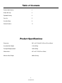
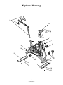
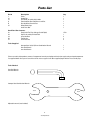
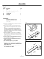
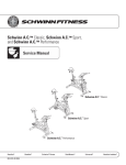
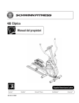
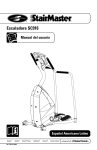
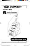
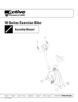
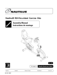
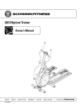
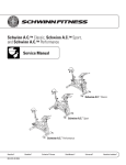
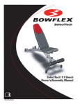
Schwinn® IC Bikes
Evolution®, Evolution® SR
Assembly Manual
Nautilus® Bowflex® Schwinn® Fitness Pearl Izumi® StairMaster® Universal® Nautilus Institute®
PN001-7189 (12/11/2007)
Table of Contents
Product Specifications
2
Safety Warnings
3
Exploded Drawing
4
Parts List
5
Assembly Steps
6
Contact Numbers
11
Product Specifications
Dimensions
50” L x 22.5” W x 40” H (127cm x 57cm x 102cm)
Assembled Unit Weight
121 lbs (55 kg)
Packaged Shipping weight
130 lbs (59 kg)
Workout Area
89” L x 61.5” W (227cm x 156cm)
Maximum User Weight
300 lbs (136 kg)
2
Assembly Manual
Safety Warnings
This icon means a potentially hazardous situation which, if not avoided, could result in death or serious injury.
Before using this equipment, obey the following warnings:
Read and understand the complete Owner’s Manual.
Read and understand all Warnings on this machine.
•
Keep children away from this machine. Watch them closely when near the machine. Moving parts that appear dangerous to adults
may not appear so to children.
• Consult a physician before starting an exercise program. Stop exercising if you feel pain or tightness in your chest, become
short of breath, or feel faint. Contact your doctor before using the machine again.
• The flywheel momentum of the Schwinn ® IC Bike will keep the pedals turning even after the rider stops pedaling or the rider’s
feet slip off. DO NOT ATTEMPT TO DISMOUNT THE BIKE OR REMOVE YOUR FEET FROM THE PEDALS UNTIL BOTH THE
PEDALS AND THE FLYWHEEL HAVE COMPLETELY STOPPED. Failure to follow these instructions may lead to loss of control
and serious personal injury.
• Examine this machine for loose parts or signs of wear. Contact Nautilus Customer Service for repair information. Use only
genuine Schwinn ® IC replacement parts supplied by Nautilus.
•
Do not wear loose clothing or jewelry. This machine contains moving parts.
•
Do not place fingers or any other objects into moving parts of the exercise equipment.
• Maximum user weight limit: 300 lb. (136 kg). Do not use if you are over this weight.
•
Stabilize the pedals before stepping on them and use caution when stepping off the machine.
• Keep at least 19.7 inches (0.5 m) on each side of the machine clear. This is the recommended safe distance for access and
passage around and emergency dismounts from the machine.
• Warn bystanders to keep a safe distance, at least 3 feet (1 m). Do not allow anyone to touch the operator while the machine is
in motion.
•
Keep the foot pedals clean and dry.
•
Do not over exert yourself during exercise. Operate the machine in the manner described in this manual.
3
Assembly Manual
Exploded Drawing
27
25
1
44
42
39
50
B
42
50
39
50
A
51
50
51
4
Assembly Manual
67
Parts List
Ref. # 1
25 27 A
B
67 Description Frame Handle Bar Seat Slider Assembly with Saddle Front Stabilizer Bar with Wheels and Feet Rear Stabilizer Bar with Feet Water Bottle Cage Small Parts Box Qty.
1
1
1
1
1
2
1
Small Part Box Contents
42 Pedals with Toe Clips & Straps (Left & Right) 44 Pop Pin Assembly for Head Tube 39 13mm Hex Bolt 50 Flat Washer 51 13mm Lock Nut 1 Pair
1
4
8
4
Tools Supplied
1
1
1
Stamped Steel 13/14/15/17mm Combination Wrench 5mm Hex Wrench 3mm Hex Wrench Prior to assembly of the product, remove all components from the packaging and check them against the packaged components
list supplied above. Once you are certain that all the necessary parts have been supplied, begin with the first assembly step.
Tools Needed
5mm Hex Wrench
3mm Hex Wrench
Stamped Steel Combination Wrench
17/15
13/14
Adjustable wrench (not included)
5
Assembly Manual
Assembly
Step 1
Ref. # Description Qty
1
Frame 1
A
Front Stabilizer Bar with Wheels and Feet 1
B
Rear Stabilizer Bar with Feet 1
39 13mm Hex Bolt 4
50 Flat Washer 8
51 13mm Lock Nut 4
Tools Required
Stamped Steel Combination Wrench 1
Adjustable wrench or 13mm Socket
1
5mm Hex Tool
1
Front
A. Position the Front Stabilizer Bar (A) under the frame bracket
as shown in the illustration.
39
B. Make sure the adjustable feet are on the bottom and the
transport wheels are facing up and toward the front of the
bike.
CAUTION: IT IS VERY IMPORTANT TO APPLY GREASE TO
THE 13mm HEX BOLT (39) PRIOR TO MOUNTING THE 13mm
LOCKNUT (51). THIS WILL ENSURE THAT YOU CAN REMOVE
THE NUT AT A LATER DATE.
1
C. Attach Front Stabilizer Bar (A) to Frame (1) using two hex
bolts (39), four washers (50), and two lock nuts (51). Tighten
hardware firmly but do not over tighten as deformation of the
stabilizer tube may occur.
A
50
50
51
D. At this time make sure that the adjustable feet with lock nuts
are screwed fully into the stabilizer.
E. Position the Rear Stabilizer Bar (B) on the frame bracket as
shown in the illustration.
Rear
F. Make sure the adjustable feet are on the bottom.
G. Attach Rear Stabilizer Bar (B) to Frame (1) using two hex
bolts (39), four washers (50), and two lock nuts (51). Tighten
hardware firmly but do not over tighten as deformation of the
stabilizer tube may occur.
39
1
50
H. At this time make sure that the adjustable feet with lock nuts
are screwed fully into the stabilizer.
B
50
51
6
Assembly Manual
Assembly
Step 2
Ref. # Description Qty
1
Frame 1
44 Pop Pin Assembly for Head Tube 1
25 Handle Bar 1
44, 27, 45 Seat Slider Assembly (Pre-Assembled) 26
Seat Post
67 Water Bottle Cage 1
2
Tools Required
Adjustable wrench 1
A. Remove the Pop Pin Assembly (44) from the small parts bag
and add some grease to the threads of the large 21mm nut
that will screw into the head tube boss on the bike.
down on the Pop Pin, push the Seat Slider Assembly onto
the seat post slider tube. When the Seat Slider has moved
far enough forward, the spring pin will pop out of the back.
This secures the Seat Slider to the seat post tube and
prevents it from inadvertently separating from the seat post
slider tube.
B. Thread the Pop Pin Assembly into the head tube boss using
a large adjustable wrench, tighten firmly.
C. Using your hand grab the T-handle of the Pop Pin, turn it
counterclockwise to make sure it is free of the securing
threads and can be pulled freely.
H. Using a 3mm Hex Wrench, remove the screws preassembled to the fork legs of the bike. Position the bottle
cage (67) on the side of the bike and tighten the screws
securely to the fork leg.
D.Insert the Handle Bar (25) into the head tube of the bike
while pulling the Pop Pin back. Insert the Handle Bar to
the desired height and release the Pop Pin. Make sure the
Pop Pin settles into one of the securing holes in the Handle
Bar tube. Turn the Pop Pin clockwise threading it into the
Pop Pin Assembly and hand tighten. This will secure the
Handlebar at the desired height.
E. Using your hand, grab the T-handle of the Pop Pin attached
to the seat tube, turn it counterclockwise to make sure it is
free of the securing threads and can be pulled freely.
F. Insert the Seat Post (26) into the seat tube while pulling
the Pop Pin back. Insert the Seat Post to the desired
height and release the Pop Pin. Make sure the Pop Pin
settles into one of the securing holes in the Seat Post tube.
Turn the Pop Pin clockwise threading it into the Pop Pin
Assembly and hand tighten. This will secure the Seat Post
at the desired height.
45
25
27
44
26
44
67
G. The Seat Slider Assembly (44,27,45) has been preassembled at the factory. Insert the front (saddle nose
side) of the Seat Slider Assembly into the back of the
seat post slider tube (horizontal tube at the top). There
is a small spring pin at the rear of the slider tube on the
Seat Post that must be depressed to allow the Seat Slider
Assembly to fully attach to the Seat Post. This can be can
be accomplished by laying the Seat Slider Assembly on
the spring pin, pushing down on the entire Seat Slider
Assembly so that the spring pin is depressed. While pulling
7
Assembly Manual
Assembly
Step 3
Ref. # Description Qty
1
Frame 1
43
Pedals with Toe Clips & Straps (Left & Right) 1 Pair
Tools Required
Stamped Steel Combination Wrench
1
A. Remove Pedals (42) from the small parts box and look at the
ends of the pedal threads. You will notice that each pedal is
market with an “R” or an “L” on the very end of the spindle
past the threads. This mark indicates which side of the bike
the pedal is intended to mount. This is important since the
thread directions are different for each pedal.
B. Locate the Pedal that has the “R” on the spindle. This pedal is
for the right side crank arm of the bike (chain guard side) and
is right hand threaded (turn clockwise to tighten). It is a good
idea to apply grease to the threads before attaching them to
the crank, this will assure that they can be removed in the
future. Using the supplied Combination Wrench thread the
right Pedal on to the crank arm, tighten firmly.
1
42
C. Locate the Pedal that has the “L” on the spindle. Follow the
directions in step B. however, you will need to turn the spindle
left (counterclockwise) to tighten as the “L” spindle is reverse
threaded.
42
8
Assembly Manual
Assembly/Initial Setup Adjustments
Step 4 - Final Inspection
A. Tighten all hardware.
B. Read warnings on machine.
Please read and refer to the Owner’s Manual for:
• Operating Instructions
• Maintenance Instructions
• Warranty Information.
Failure to visually check and test assembly before use can cause damage to the equipment.
It can also cause serious injury to users and bystanders.
To assure optimal performance and longevity, perform the following steps prior to placing your Schwinn®
Evolution® bike into service.
A. Move bike into its final location. Confirm that all four feet are firmly in contact with the floor and that the bike is stable. If any of the
feet are not making full contact, it is recommended that you adjust them by turning the entire foot assembly counterclockwise which
will extend it further from the stabilizer bar. Once the foot is in full contact and the bike is stable, thread the jam nut clockwise until it
comes into contact with the stabilizer at the point the foot assembly threads in. Tighten the jam nut snug using an adjustable wrench.
This will secure the foot at the desired height.
B. With the resistance adjustment knob turned fully in the counterclockwise position (no brake contact with flywheel), it is
recommended that you soak the brake pads with Schwinn® Fit-Tech Lube. This will extend the life of the brake pads and assure a
smooth resistance interface with the flywheel.
C. Once the pads are lubricated, it is recommended that you tighten the resistance adjustment knob clockwise to tighten the brake
pads against the flywheel surface. Do this until the brake pads are firmly clamped against the flywheel. This will set the brake parts
and give the springs some initial compression. This process will also assure that the Fit-Tech Lube penetrates the entire brake pad
surface.
D. Confirm that the Saddle is positioned in the desired location on the saddle mounting bracket. If the angle of the saddle or the
fore/aft position of the saddle needs to be adjusted, use the Combination Wrench to loosen the 14mm nuts on either side of the
saddle mounting bracket. This will allow you to adjust the tilt angle and fore/aft position of the saddle. Once in the correct position,
tighten both 14mm nuts on the saddle mounting bracket with the Combination Wrench.
That’s it! Initial set up is complete and you can now enjoy all these features and quality of your new Schwinn®
IC Bike!
9
Assembly Manual
Assembly
This page intentionally left blank.
10
Assembly Manual
Contact Numbers
OFFICES IN THE UNITED STATES:
INTERNATIONAL OFFICES:
E-mail: [email protected]
For technical assistance and a list of distributors in your
area, please call or fax one of the following numbers.
TECHNICAL/CUSTOMER SERVICE
Phone: 800-NAUTILUS (800-628-8458)
Fax: (877) 686-6466
E-mail: [email protected]
INTERNATIONAL CUSTOMER SERVICE
Nautilus International S.A.
Rue Jean Prouvé
1762 Givisiez / Switzerland
Tel: (41) (26) 460 77 77
Fax: (41) (26) 460 77 70
E-mail: [email protected]
CORPORATE HEADQUARTERS
Nautilus, Inc.
World Headquarters
16400 SE Nautilus Drive
Vancouver, Washington, USA 98683
Phone: (800) NAUTILUS (800) 628-8458
GERMANY and AUSTRIA
Nautilus Deutschland GmbH
Albin-Köbis-Str. 4
51147 Köln
Tel.: (49) 02203 2020 0
Fax: (49) 02203 2020 45 45
ITALY
Nautilus Italy S.r.l., Via della Mercanzia, 103
40050 Funo di Argelato - Bologna
Tel: (39) 051 664 6201
Fax: (39) 051 664 7461
SwITZERLAND
Nautilus Switzerland SA
Rue Jean-Prouvé 6,
CH-1762 Givisiez
Tel: (41) 026 460 77 66
Fax: (41) 026 460 77 60
United Kingdom
Nautilus UK Ltd
Nautilus UK, 4 Vincent Avenue,
Crownhill, Milton Keynes, Bucks, MK8 0AB
Tel: (44) 1908 267 345
Fax: (44) 1908 567 346
chinA
Nautilus Representative Office
Nautilus, Shanghai, 7A No.728, Yan’an Rd(West)
200050 Shanghai, China
Tel: (86) 21 523 707 00
Fax: (86) 21 523 707 09
11
Assembly Manual
©2007. Nautilus, Inc. All rights reserved. Nautilus, the Nautilus Logo, Universal, Bowflex, StairMaster, Pearl Izumi and Nautilus Institute are either registered trademarks or trademarks of Nautilus, Inc. Schwinn and the Schwinn Quality Seal are registered trademarks. All other trademarks are owned by their respective companies. Nautilus, Inc., World Headquarters, 16400 SE Nautilus
Drive, Vancouver, WA 98683 1-800-NAUTILUS www.nautilus.com
Printed in China
Nautilus®
Bowflex®
Schwinn® Fitness
Pearl Izumi®
StairMaster®
Universal®
Nautilus Institute®