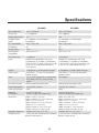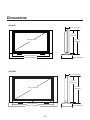
1
O W N E R ’S O P E R A T I N G M A N U A L
C R - 3 2 HD / CR-40HD
with
Crystal Series™ LCD Displays
Table of Contents
One Year Limited Warranty ......................................................................4
Introduction...............................................................................................7
Precautions ...............................................................................................8
Control Panels
CR-32HD and CR-40HD Front View ................................................................................ 9
CR-32HD Rear View and Input Panel............................................................................... 10
CR-40HD Rear View and Input Panel............................................................................... 11
Remote Control ............................................................................................................... 12
Connections
Connecting an Antenna or Cable ..................................................................................... 13
Connecting to the Video or S-Video Input (INPUT1 or INPUT2) ........................................ 13
Using the MONITOR OUT feature .................................................................................... 14
Connecting to a DVD or DTV Set-Top Box INPUT (RCA or DVI) ....................................... 14
Connecting to a PC ......................................................................................................... 15
Setting the PC Properties ................................................................................................ 16
Connecting Headphones ................................................................................................. 16
Basic Operations
Connecting the Power Cord and Switching the Display On/Off ........................................ 17
Selecting a Source ........................................................................................................... 17
Selecting an Aspect Ratio ................................................................................................ 18
Selecting Picture Adjust ................................................................................................... 19
Selecting Audio................................................................................................................ 20
Selecting Channel (For CR-32HD only) ............................................................................ 20
Selecting Timer ................................................................................................................ 21
Setup
OSD Language ................................................................................................................ 22
PC Mode Adjust .............................................................................................................. 22
Caption............................................................................................................................ 23
Parental Control ............................................................................................................... 23
Letterbox Mode ............................................................................................................... 23
Input Selection ................................................................................................................. 24
Monitor Out ..................................................................................................................... 24
Overscan ......................................................................................................................... 24
2
ISF Calibration (Service)
Picture Adjust .................................................................................................................. 25
White Balance ................................................................................................................. 25
Blue Enable ..................................................................................................................... 26
DNR ................................................................................................................................ 26
Gamma ........................................................................................................................... 26
Baud Rate ....................................................................................................................... 26
Command ACK ............................................................................................................... 26
Factory Reset .................................................................................................................. 26
Splash Duration ............................................................................................................... 26
Picture in Picture (PIP)
Displaying the Picture in Picture (PIP) ............................................................................... 27
Changing the PIP Position ............................................................................................... 28
Changing the PIP Size ..................................................................................................... 28
Selecting the Image Size in the PIP .................................................................................. 28
Selecting the Image Mode in the PIP ............................................................................... 28
Swapping the Main & Sub-Picture ................................................................................... 29
Swapping the Main & Sub-Sound .................................................................................... 29
Changing the PIP Aspect Ratio ........................................................................................ 30
Stereo Sound / SAP
Listening to Stereo Sound / SAP...................................................................................... 31
RS-232 Configurations
RS-232C Configurations ................................................................................................. 32
Serial Protocol ................................................................................................................. 33
Signals Supported
Standard Display Mode ................................................................................................... 35
Pin Configuration (PC/DVI)
PC Input Connector (D-Sub 15Pin) .................................................................................. 36
DVI-D Connector ............................................................................................................. 36
Troubleshooting
For Display Panel ............................................................................................................. 37
For Monitor ...................................................................................................................... 38
Specifications ............................................................................................................... 39
Dimensions .................................................................................................................... 40
3
One Year Limited Warranty
Congratulations on your purchase of Runco’s latest video product and welcome to the Runco family! We believe
Runco produces “The World’s Finest Home Theater Products”. With proper installation, setup and care, you should
enjoy many years of unparalleled video performance.
This is a LIMITED WARRANTY as defined in the Magnuson-Moss Warranty Act. Please read it carefully and retain
it with your other important documents.
WHAT IS COVERED UNDER THE TERMS OF THIS LIMITED WARRANTY:
SERVICE LABOR: Runco will pay for service labor by a Runco Authorized Service Center when needed as a result
of a manufacturing defect for a period of one (1) year from the effective date of delivery to the end user.
PARTS: Runco will provide new or rebuilt replacement parts for the parts that fail due to defects in materials or
workmanship for a period of one (1) year from the effective date of delivery to the end user. Such replacement parts
are then subsequently warranted for the remaining portion (if any) of the original warranty period.
WHAT IS NOT COVERED UNDER THE TERMS OF THIS LIMITED WARRANTY:
Image retention on LCD display panels are specifically excluded from coverage under this Limited Warranty. Image
retention or staining of an image is the result of misuse of the product and therefore cannot be repaired under the
terms of this Limited Warranty.
Normal viewing material such as television/satellite broadcasts, videotape or DVDs (not put into pause for extended
periods of time) will not cause damage to your display under normal conditions. Many DVD players are also
equipped with screen savers for this reason.
TO AVOID IMAGE RETENTION (Burn-in):
Please ensure that still images are not left on your LCD display panel. Also ensure that images displayed in the
4:3 aspect ratio mode (black or gray stripes, but no picture information is present on the left and right edges of the
screen) are used as infrequently as possible. This will prevent permanent image burns on your LCD display panel,
which can be seen permanently under certain conditions once burn-in has occurred.
The types of images to avoid include video games, still images and computer screens with stationary tool bars
and icons. (This is why computers are equipped with screen savers – to prevent still images from burning into the
monitor’s phosphors after being displayed continuously for an extended period of time).
4
This Limited Warranty only covers failure due to defects in materials and workmanship that occur during normal use
and does not cover normal maintenance. This Limited Warranty does not cover cabinets or any appearance items;
failure resulting from accident, misuse, abuse, neglect, mishandling, misapplication, faulty or improper installation
or setup adjustments; improper maintenance, alteration, improper use of any input signal; damage due to lightning
or power line surges, spikes and brownouts; damage that occurs during shipping or transit; or damage that is
attributed to acts of God. In the case of remote control units, damage resulting from leaking, old, damaged or
improper batteries is also excluded from coverage under this Limited Warranty.
CAUTION: THIS LIMITED WARRANTY ONLY COVERS RUNCO PRODUCTS PURCHASED FROM RUNCO
AUTHORIZED DEALERS. ALL OTHER PRODUCTS ARE SPECIFICALLY EXCLUDED FROM COVERAGE
UNDER THIS LIMITED WARRANTY. MOREOVER, DAMAGE RESULTING DIRECTLY OR INDIRECTLY FROM
IMPROPER INSTALLATION OR SETUP IS SPECIFICALLY EXCLUDED FROM COVERAGE UNDER THIS LIMITED
WARRANTY.
RIGHTS, LIMITS AND EXCLUSIONS:
Runco limits its obligations under any implied warranties under state laws to a period not to exceed the warranty
period. There are no express warranties. Runco also excludes any obligation on its part for incidental or consequential
damages related to the failure of this product to function properly. Some states do not allow limitations on how long
an implied warranty lasts, and some states do not allow the exclusion or limitation of incidental or consequential
damages. So the above limitations or exclusions may not apply to you. This warranty gives you specific legal rights,
and you may also have other rights that vary from state to state.
EFFECTIVE WARRANTY DATE:
This warranty begins on the effective date of delivery to the end user. For your convenience, keep the original bill of
sale as evidence of the purchase date.
IMPORTANT - WARRANTY REGISTRATION:
Please fill out and mail your warranty registration card. It is imperative that Runco knows how to reach you promptly
if we should discover a safety problem or product update for which you must be notified.
CONTACT A RUNCO AUTHORIZED SERVICE CENTER TO OBTAIN SERVICE:
Repairs made under the terms of this Limited Warranty covering your Runco video product will be performed at
the location of the product, during usual working hours, providing location of product is within normal operating
distance from a Runco Authorized Service Center. In some instances it may be necessary for the product to be
returned to the Runco factory for repairs. If, solely in Runco’s judgment, location of product to be repaired is
beyond normal operating distance of the closest Runco Authorized Service Center, or the repair requires the unit
be returned to the Runco factory, it is the owner’s responsibility to arrange for shipment of the product for repair.
These arrangements must be made through the selling Runco Dealer. If this is not possible, contact Runco directly
for a Return Authorization number and shipping instructions. Runco will return product transportation prepaid in
the United States, unless no product defect is discovered. In that instance, shipping costs will be the responsibility
of the owner.
5
ADDITIONAL INFORMATION:
To locate the name and address of the nearest Runco Authorized Service Center, or for additional information about
this Limited Warranty, please call or write:
RUNCO INTERNATIONAL, INC.
Attn: Customer Service Department
2900 Faber Street
Union City, CA 94587
Ph: (510) 324-7777
Fax: (510) 324-9300
Toll Free: (800) 23-RUNCO
RUNCO VIDEO PRODUCT INFORMATION
RETAIN THIS INFORMATION FOR YOUR RECORDS
Model Purchased
Date
Serial Number
Runco Authorized Dealer Name
Address
City
State/Province
Phone
Fax
6
Postal Code
Introduction
Runco presents the high performance Crystal Series™ LCD displays, perfect for
those who demand our award-winning flat panel performance in more intimate
sizes than we offer with our larger plasma monitors.
The new Crystal Series™ high definition capable LCD displays offer common
features and performance in popular 26, 32 and 40-inch sizes, suitable for
close-in viewing where picture quality remains a high priority, but larger displays
cannot be accommodated.
The Crystal Series™ models incorporate the superb Vivix™ digital video
processing that produces outstanding picture quality with a wide range of both
standard and high definition source material.
In addition, these handsome, gloss black televisions are engineered with ISF™
calibration standards in every model for the purest video performance. The CR32HD also features an advanced, 185 channel cable-ready NTSC stereo tuner
offering PIP, POP, closed captioning, Parental Control (V-Chip) functionality and
multi-language support. Both the CR-32HD and CR-40HD include integrated
stereo audio systems incorporating surround sound technology with 2-way
speakers and generous power amplification.
The advanced TFT active matrix LCD display panels offer 1366 x 768 resolution
on both models and include Runco’s discrete aspect ratio control with
VirtualWide™ mode to fill the 16:9 screen with standard 4:3 images without
loss of picture quality. Also included are discrete source, aspect ratio and power
selection and an RS-232 interface for whole house or automated control system
integration.
The Crystal Series™ CR-32HD and CR-40HD are multimedia ready, with simple
computer connections making gaming, internet browsing and other computer
activities quick and easy.
7
Precautions
This symbol is intended to alert the user to the presence of uninsulated “dangerous voltage” within the product’s
enclosure that may be of sufficient magnitude to constitute a risk of electric shock to persons.
This symbol is intended to alert the user to the presence of important operating and maintenance (servicing)
instructions in the literature accompanying the appliance.
CAUTION
To turn off main power, be sure to remove the plugs from power outlets. The power outlet socket should be installed as
near to the equipment as possible, and should be easily accessible.
WARNING
TO PREVENT FIRE OR SHOCK HAZARDS, DO NOT EXPOSE THIS UNIT TO RAIN OR MOISTURE. ALSO
DO NOT USE THIS UNIT’S POLARIZED PLUG WITH AN EXTENSION CORD RECEPTACLE OR OTHER
OUTLETS, UNLESS THE PRONGS CAN BE FULLY INSERTED REFRAIN FROM OPENING THE CABINET
AS THERE ARE HIGH-VOLTAGE COMPONENTS INSIDE. REFER SERVICING TO QUALIFIED SERVICE
PERSONNEL.
WARNING
This equipment has been tested and found to comply with the limits for a Class ‘B’ digital device, pursuant to Part 15
of the FCC Rules. These limits are designed to provide reasonable protection against harmful interference when the
equipment is operated in a commercial environment. This equipment generates, uses, and can radiate radio frequency
energy and, if not installed and used in accordance with the Installation Manual, may cause harmful interference to radio
communications. Operation of this equipment in a residential area may cause harmful interference, in which case, the user
will be required to correct the interference at his own expense.
DOC compliance Notice
This Class B digital apparatus meets all requirements of the Canadian Interference-Causing Equipment Regulations.
Please read and follow the safety precautions listed below to ensure the equipment is free from damage, and to ensure
that no injury will occur as a result of improper use.
·
·
·
·
·
·
Do not insert any object, especially metal or liquids, into the LCD display.
Do not place any objects containing water or any other liquid on top of the LCD display.
Do not place the units in direct sunlight, near heaters or in extremely dusty or humid locations.
Do not install this system outdoors or otherwise exposed to the elements.
Do not place heavy objects on top of the LCD display.
If the power cord is damaged or frayed in any way, electrical shock and/or fire may result. Do not place objects on
the power cord, and keep the cord away from heat-emitting devices. Should the power cord become damaged in any
way, please contact your Runco Dealer for a replacement cord.
· Do not remove the cover of the LCD display for any reason. If any problems arise with the unit, please contact a Runco
Dealer or Runco International for service. Removing the covers will void the warranty.
8
Control Panels
CR-32HD and CR-40HD
Front View
8
8
Bottom Side
TV/AV
MENU
1
2
-
VOL
+
3
1 TV/AV Button (Input Source Selection)
2 MENU Selection Button
3 Volume Adjustment Buttons
4 Channel Selection Buttons
5 Remote Control Sensor
CH
4
5
6
7
Power Indicator Status
Indicator
Status
Red
Green
Green blinking
Stand-by
Power on
Remote control
6 Power Button
7 Power Indicator
8 Speakers
9
Control Panels
CR-32HD Rear View and
Input Panel
Right Side
Input2
1
S-VIDEO
Audio
L
2
R
3
VIDEO
4
Bottom Side
11
12 13
INPUT4
INPUT3
5
6
7
8
9
MONITOR-OUT
10
14 15
INPUT1
16 17 18
19
20
21 22
1 INPUT2 S-Video Input
12 INPUT4 Video Input (VIDEO)
2 INPUT2 Audio Input
13 INPUT4 Audio Input (DTV/DVD)
3 INPUT2 Video Input
14 INPUT1 Video Input
4 Headphone Jack
15 INPUT1 Audio Input
5 RGB Input Connector (PC)
16 INPUT1 S-Video Input
6 DVI-D Input Connector (PC)
17 MONITOR-OUT (Video)
7 Audio Input (PC)
18 MONITOR-OUT (Audio)
8 INPUT3 Video Input (DTV/DVD)
19 Antenna/cable Input Jack
9 INPUT3 Video Input (VIDEO)
20 SERVICE Port (For RS-232 Control)
10 INPUT3 Audio Input (DTV/DVD)
21 Power Switch (Main)
11 INPUT4 Video Input (DTV/DVD)
22 Power Input
10
Control Panels
CR-40HD Rear View and
Input Panel
Right Side
Input2
1
S-VIDEO
L
Audio
2
R
3
VIDEO
4
Bottom Side
13
14
15
INPUT4
INPUT3
MONITOR-OUT
INPUT1
5
6
7
8
9
10
11
12
16
17 18
19
20
1 INPUT2 S-Video Input
12 INPUT3 Audio Input (DTV/DVD)
2 INPUT2 Audio Input
13 INPUT4 Video Input (DTV/DVD)
3 INPUT2 Video Input
14 INPUT4 Video Input (VIDEO)
4 Headphone Jack
15 INPUT4 Audio Input (DTV/DVD)
5 Power Switch (Main)
16 INPUT1 Video Input
6 Power Input
17 INPUT1 Audio Input
7 RGB Input Connector (PC)
18 INPUT1 S-Video Input
8 DVI Input Connector (PC)
19 MONITOR-OUT (Video)
9 Audio Input (PC)
20 MONITOR-OUT (Audio)
10 INPUT3 Video Input (DTV/DVD)
21 SERVICE Port (For RS-232 Control)
11 INPUT3 Video Input (VIDEO)
11
21
Control Panels
Remote Control
OFF Button
To turn off the unit.
ON Button
OFF
Hold down this button for one second to
turn on the unit.
1
2
3
4
5
6
7
8
9
100
0
TIMER
OFF
NUMERIC Buttons
To select channel and to enter pass
codes.
The “100” button is to select channels
over 100.
DISCRETE SOURCE SELECTION
• INPUT 1
For Composite video or S-Video signals.
• INPUT 2
For Composite video or S-Video signals.
• INPUT 3
For Component video or composite
video signals.
• INPUT 4
For Component video or composite
video signals.
• RGB HD
INPUT
1
INPUT
2
INPUT
3
RGB
HD
TV
SLEEP
MEMORY
DISPLAY
CUST
ISF
NT
ISF
DAY
ASPECT RATIO
ANA
4X3
LET
BOX
VWIDE
CHANNEL UP
To display the OSD menu.
PIP FUNCTION Buttons
See page 27-30 for Operation
instructions.
ASPECT RATIO Buttons
• ANA
For Anamorphic 16:9 or widescreen
enhanced DVD.
• LETTERBOX
VOL -
ENTER
VOL +
Image in letterbox format is enlarged to fit
16:9 full screen display and the upper/
lower portion are “blanked off”.
• VIRTUALWIDE
ENTER Button
MENU Button
To recall video memory sequentially.
For standard video format.
For ant/cable signals. (CR-32HD only)
To enter the setting of items in the menu.
MEMORY Buttons
• 4X3
• TV
To select the menu or to make various
adjustments.
To access sleep timer.
INPUT
4
DVI
For DTV RGBHV or PC signals.
ARROW Buttons
TIMER OFF Button
SOURCE
• DVI
For Digital video input signals.
ON
MENU
CHANNEL DOWN
EXIT
ASPECT
SIZE
POSITION
PIP
P.MODE
S.SWAP
SWAP
TV/AV
4:3 image is nonlinearly stretched in a
horizontal direction to fit 16:9 full screen
display.
EXIT Button
To clear the OSD menu.
HOLD
SUB PAGE
CANCEL
TEXT
S.MODE
SURRND
MTS/SAP
MUTE
REVEAL
SIZE
MIX
INDEX
FC1
FC2
FC3
FC4
SOUND SELECTION Buttons
See page 20, 31 for menu diagram.
FAVORITE CHANNEL Buttons
See page 21 for menu diagram.
Note:
• Makes sure there are no objects between
the remote control and its sensor.
• Don’t place the remote control near a heater
or in damp place.
• A strong blow to the remote control may
cause it not to operate.
12
Connections
To view television channels, a signal must be
input from either an outdoor antenna or a cable
television system.
1. Connect the antenna or input cable to the 75
Ω coaxial input on the rear of the display.
2. If you are using an indoor antenna, you may
need to turn it when tuning your television until
you receive a clear picture.
Connecting an Antenna
or Cable (Not applicable on
the CR-40HD)
Rear of the TV
ANT
or
Cable Television
Network
Rear of the display
(A) For Video (RCA) Input
Connecting to the Video
or S-Video Input (INPUT1
or INPUT2)
INPUT1
Right side of the display
Input2
S-Video
(B) For S-Video Input
R
Audio
L
Video
(A) For Video Input
1. Connect the RCA cable to the input jacks (video+ audio L/R of Input1 or Input2) on
the display and output jacks on the external equipment such as a VCR, camcorder
and some video game devices.
(B) For S-Video Input
1. Connect the S-Video/RCA (audio L/R of Input1 or Input2) cable to the input jacks on
the display and output jacks on the external equipment such as a VCR, camcorder
and some video game devices.
2. If the external equipment has mono audio output, connect it only to left jack of the
Audio Input/Output.
13
Connections
Using the MONITOR OUT
feature
You can choose the Main or PIP screen to record. Refer to page 24 for more
information.
Rear of the display
VCR, etc.
MONITOR-OUT
• Your display has a monitor out feature which can be used by a second VCR, or other
auxiliary equipment.
To do this, connect your second VCR as follows:
1. Connect a set of audio cables between the AUDIO OUT jacks on the display and
the AUDIO IN jacks on the VCR, or auxiliary equipment.
2. Connect a video cable between the VIDEO OUT jack on the display and the VIDEO
IN jack on the VCR, or auxiliary equipment.
Connecting to a DVD or
DTV Set-Top Box INPUT
(RCA or DVI)
Rear of the display
INPUT4
INPUT3
1. Connect the video cables to the Y, Pb, Pr input jacks (INPUT3 or INPUT4) on the
display and the Y, Pb, Pr output jacks on the DVD or DTV Set-Top Box.
2. Connect the audio cables to the Audio L/R input jacks (INPUT3 or INPUT4) on the
display and the Audio output jacks on the DVD or DTV Set-Top Box.
1. Connect the DVI cables to the DVI input jacks (DVI) on the display and the DVI output
jacks on the DVD or DTV Set-Top Box.
2. Connect the audio cables to the Audio L/R input jacks on the display and the Audio
output jacks on the DVD or DTV Set-Top Box.
14
Connections
To use the display as a PC Monitor
TIMER
OFF
0
100
SOURCE
1. Turn the PC on.
INPUT
1
2. Depending on the connection, press the DVI or
RGB HD button on the remote control.
3. Set up the PC Properties. (See page 16)
4. Adjust the screen in PC Mode. (See page 22)
INPUT
2
INPUT
3
DVI
RGB
HD
TV
SLEEP
MEMORY
DISPLAY
CUST
ISF
NT
ISF
DAY
RGB
Rear of the Display
Rear of the PC
1 2 3 4 5 6 7 8
9 10 11 12 13 14 15 16
17 18 19 20 21 22 23 24
Audio Cable
(Sold Separately)
D-Sub 15 Pin Cable (Sold Separately)
Connect the D-Sub 15 Pin Cable to the RGB Input port on the TV
and output port on the Rear of the PC.
DVI-D
Rear of the Display
INPUT
4
Rear of the PC
1 2 3 4 5 6 7 8
9 10 11 12 13 14 15 16
17 18 19 20 21 22 23 24
Audio Cable
(Sold Separately)
DVI-D Cable (Sold Separately)
Connect the DVI-D Cable to the DVI Input port on the TV
and output port on the Rear of the PC.
15
Connecting to a PC
Connections
Setting the PC Properties
1. First, click on Settings on the Windows Start menu and click on “Control Panel”.
2. Double click on the Display icon.
3. Click on the Settings tab on the display dialog-box.
4. Adjust the resolution to 1024x768 pixels.
5. Click the Advanced button and click the Monitor
tab on the dialog-box. Set the vertical-frequency
to 60Hz and then click the OK button.
Note:
– Maximum resolution depends on the Video
Card.
– Maximum supported resolution is 1024 x 768
@ 75Hz. You can get the best picture at 1024
x 768 @ 60Hz.
– There are 16,770,000 supported colors.
Connecting Headphones
Right side of the display
Input2
S-Video
R
Audio
L
Video
You can connect a set of headphones to your display if you wish to watch a program
without disturbing other people.
1. Plug a set of headphones into the 3.5mm mini-jack socket on the right side of your
display. Sound will then be routed through the headphones.
Note: Headphones are not included.
16
Basic Operations
1. Connect the power cord for your display to the power input on the back of your
display.
2. Plug the power cord for the display into a nearby outlet.
3. Press the POWER (
display panel.
) button on the remote control or the POWER button on the
4. To switch your display off, press the POWER (
the POWER button on the display panel.
Connecting the Power
Cord and Switching the
Display On / Off
) button on the remote control or
OFF
ON
1
2
3
4
5
6
7
8
9
0
TIMER
OFF
100
SOURCE
INPUT
1
INPUT
2
INPUT
3
INPUT
4
1. Press the MENU button on the remote control.
2. Press the ▲▼ buttons to select Source and then press the ENTER or ► button.
3. Select the appropriate Source by pressing the ▲▼ buttons and then press the
ENTER or ► button.
• You can select TV, Input 1, Input 2, Input 3, Input 4, DVI or RGB.
4. Press the MENU button to return to the previous menu.
OR
You can also select the Source directly from the remote control using discrete
source buttons.
Source
Aspect Ratio
Picture Adjust
Audio
Channel
Timer
Setup
ISF Calibration
TIMER
OFF
0
100
Runco CR-32HD
SOURCE
> TV
Input 1
Input 2
Input 3
Input 4
INPUT
1
INPUT
2
INPUT
3
INPUT
4
DVI
RGB
HD
TV
SLEEP
MEMORY
DISPLAY
CUST
ISF
NT
ISF
DAY
DVI
RGB
17
Selecting a Source
Basic Operations
Selecting an Aspect
Ratio
1. Press the MENU button on the remote control.
2. Press the ▲▼ buttons to select Aspect Ratio and then press the ENTER or ►
button.
3. Select the appropriate Aspect Ratio by pressing the ▲▼ buttons and then press
the ENTER or ► button.
• You can select Anamorphic, Standard, Letterbox or VirtualWide.
4. Press the MENU button to return to the previous menu.
OR
You can also select the Aspect Ratio directly from the remote control using discrete
Aspect Ratio buttons.
0
100
Runco CR-32HD
TIMER
OFF
SOURCE
INPUT
1
Source
Aspect Ratio
Picture Adjust
Audio
Channel
Timer
Setup
ISF Calibration
> Anamorphic
Standard
Letterbox
VirtualWide
INPUT
2
INPUT
3
INPUT
4
DVI
RGB
HD
TV
SLEEP
MEMORY
DISPLAY
CUST
ISF
NT
ISF
DAY
ASPECT RATIO
ANA
4X3
LET
BOX
VWIDE
CHANNEL UP
ANAMORPHIC mode
The Anamorphic aspect ratio expands the image in the
horizontal direction. The image is compressed vertically,
but with anamorphic software the image will appear
properly proportioned. This is best suited for use with
16:9 DVD’s and HDTV.
STANDARD 4:3 mode
The image is displayed at a standard 4:3 aspect ratio.
The input signal will be scaled to fit in the center of the
16:9 screen.
LETTERBOX mode
The image in the Letterbox mode will be zoomed in, and
the top and bottom portion ‘blanked off.’ This ratio is best
suited for LaserDisc movies or non-anamorphic DVD’s.
VIRTUALWIDE mode
The VirtualWide mode is an aspect ratio is designed to
fill the 16:9 screen with a 4:3 image. The center of the
picture is not stretched, and it gradually stretches on the
sides reaching the most extreme stretch at the far edges
of the picture (non-linear scaling). In addition, we apply
a very slight vertical stretch uniformly (no graduation)
which results in a very small amount of cropping of the
top and bottom of the image area. Thus a 4:3 image is
transformed into a 16:9 image with minimal distortion.
18
Active Image Area
Active
Image
Area
Active Image Area
Active
Image
Area
Basic Operations
1. Press the MENU button on the remote control.
2. Press the ▲▼ button to select PICTURE ADJUST and then press the ENTER
or ► button.
3. Press the ▲▼ button to select Brightness, Contrast, Color, Tint, Sharpness,
Color Temp., Backlight, Save Settings or Restore Settings.
4. Press the MENU button to return to the previous menu.
Runco CR-32HD
Note:
Each input and scan rate has their own
picture memories. Make sure you store
your picture settings before you switch
to another input or scan rate.
Picture Adjust
Brightness
Source
Aspect Ratio
Picture Adjust
Audio
Channel
Timer
Setup
ISF Calibration
Contrast
Color
Tint
Sharpness
Color Temp.
Backlight
Save Settings
Restore Settings
Color Temp.
Picture Adjust
Picture Adjust
Brightness
Brightness
50
Brightness
Contrast
Contrast
50
Contrast
Color
Color
50
Color
Tint
Tint
50
Tint
Sharpness
Sharpness
50
Sharpness
Backlight
100
Color Temp.
Color Temp.
Backlight
Backlight
Save Settings
Save Settings
Restore Settings
Restore Settings
5400
6500
8500
> Custom
Note:
Temperature 5400, 6500, 8500
are global selections and are not
adjustable. If Color Temp. requires
calibration, you must select
Custom and make adjustments
in the ISF Menu under White
Balance. (See page 25)
Save Settings
Restore Settings
Picture Adjust
Picture Adjust
Brightness
Brightness
Contrast
Contrast
Color
Color
Tint
Tint
Sharpness
Sharpness
Color Temp.
Color Temp.
Backlight
Backlight
Save Settings
Restore Settings
Custom
Save Settings
Restore Settings
19
Custom
ISF Night
ISF Day
Selecting Picture Adjust
Basic Operations
Selecting Audio
1. Press the MENU button on the remote control.
2. Press the ▲▼ buttons to select Audio and then press the ENTER or ► button.
3. Press the ▲▼ buttons to select Balance, Equalizer or Surround.
4. Press the MENU button to return to the previous menu.
Balance
Runco CR-32HD
Audio
Balance
Source
Aspect Ratio
Picture Adjust
Audio
Channel
Timer
Setup
ISF Calibration
Surround
Audio
Balance
1. Adjust the Sound Balance with
the ◄ ► buttons.
Equalizer
Surround
Surround
Equalizer
Note:
When Surround is selected,
the Equalizer feature is
automatically “grayed out.”
Audio
Balance
Equalizer
Surround
0
Equalizer
Standard
Music
Film
Speech
> Custom
Audio
Balance
Equalizer
100
300
1K
3K
10K
Surround
On
> Off
1. Press the ▲▼ buttons to select Equalizer and then press the ENTER or ► button.
2. Press the ▲▼ buttons to select Standard, Music, Film, Speech and Custom on
the remote control or the (
) to toggle between the selection.
S-MODE
3. Press the ▲▼ buttons to select Custom and then press the ENTER or ► button.
Press the ◄ ► buttons to select the frequency. The frequency range will be
selected as the following order: 100 ➞ 300 ➞ 1K ➞ 3K ➞ 10K
Press the ▲▼ buttons to make the adjustments.
Selecting Channel
1. Press the MENU button on the remote control.
(For the CR-32HD only)
2. Press the ▲▼ buttons to select Channel and then press the ENTER or ► button.
3. Press the ▲▼ buttons to select TV/CATV, Auto Tuning, Add/Erase,
Fine Tune or Favorite Channel.
4. Press the MENU button to return to the previous menu.
Runco CR-32HD
Source
Aspect Ratio
Picture Adjust
Audio
Channel
Timer
Setup
ISF Calibration
TV / CATV
Channel
20
Channel
TV / CATV
TV / CATV
Auto Tuning
Auto Tuning
Add / Erase
Add / Erase
Fine Tune
Fine Tune
Favorite Channel
Favorite Channel
> TV
CATV
Basic Operations
Auto Tuning
Add /Erase
Channel
Channel
TV / CATV
Auto Tuning
Add / Erase
TV / CATV
Start
Return
Auto Tuning
Add / Erase
Fine Tune
Fine Tune
Favorite Channel
Favorite Channel
Fine Tune
CATV 42
not in memory
Add
Favorite Channel
Channel
Channel
TV / CATV
TV / CATV
Auto Tuning
Auto Tuning
1:
2:
3:
4:
Add / Erase
Add / Erase
0
Fine Tune
Fine Tune
Favorite Channel
Favorite Channel
CATV 20
CATV 88
AIR 8
---
1. Press the MENU button on the remote control.
2. Press the ▲▼ buttons to select Timer and then press the ENTER or ► button.
3. Press the ▲▼ buttons to select Timer, On Timer, Off Timer or Sleep Timer.
4. Press the MENU button to return to the previous menu.
Timer
Runco CR-32HD
Timer
--:--
Time
Source
Aspect Ratio
Picture Adjust
Audio
Channel
Timer
Setup
ISF Calibration
On Timer
Off Timer
Sleep Timer
Timer
Time
On Timer
Off Timer
Sleep Timer
1. Press the ▲▼ buttons to select the
hour or minutes.
2. Press the ◄ ► buttons to adjust the
hour and minutes.
3. Press the Menu button to exit.
Off Timer
On Timer
Timer
Timer
Time
On Timer
Off Timer
Sleep Timer
Active
Time
Channel
Volume
No
AM 12:00
AIR 2
20
Time
On Timer
Off Timer
Active
Time
Sleep Timer
No
AM 12:00
1. Press the ▲▼ buttons to highlight
On Timer and press the Enter button.
1. Press the ▲▼ buttons to highlight
Off Timer and press the Enter button.
2. Press the ▲▼ buttons to make the
selection.
2. Press the ▲▼ buttons to make the
selection.
3. Press the ◄ ► buttons to make the
adjustments.
3. Press the ◄ ► buttons to make the
adjustments.
Sleep Timer
Timer
1. Press the ▲▼ buttons to highlight Sleep Timer and
press the Enter button.
Time
On Timer
Off Timer
Sleep Timer
Off
2. Press the ◄ ► buttons to select the desired minutes.
(Maximum Sleep Timer is 3 hours.)
21
Selecting Timer
Setup
1. Press the MENU button on the remote control.
2. Press the ▲▼ buttons to select Setup and then press the ENTER or ► button.
3. Press the ▲▼ buttons to select OSD Language, PC Adjust, Caption, Parental
Control, Letterbox Mode, Input Selection, Monitor Out or Overscan.
4. Press the MENU button to return to the previous menu.
Runco CR-32HD
Source
Aspect Ratio
Picture Adjust
Audio
Channel
Timer
Setup
ISF Calibration
Setup
OSD Language
PC Mode Adjust
Caption
Parental Control
Letterbox Mode
Input Selection
Monitor Out
Overscan
OSD Language
Setup
OSD Language
PC Mode Adjust
Caption
Parental Control
Letterbox Mode
> English
Français
Español
Português
Deutsch
Input Selection
Monitor Out
Overscan
PC Mode Adjust
Setup
OSD Language
PC Mode Adjust
Caption
Parental Control
Letterbox Mode
Input Selection
Monitor Out
PC Mode Adjust
Auto Adjust
H. Position
V. Position
H. Size
Phase
Reset
Note:
313
34
1344
0
PC Mode Adjust active only through
RGB input with VESA computer
standards.
Overscan
1. Press the ▲▼ buttons to select PC Mode Adjust and then press the ENTER or
► button.
2. Press the ▲▼ buttons to make the selection.
3. Press the ◄ ► buttons to make the adjustments.
For best results, select 1024 x 768 from your computer output.
22
Setup
Caption
Setup
OSD Language
PC Mode Adjust
Caption
Parental Control
Letterbox Mode
Display
Mode
CC On Mute
On
CC3
No
Input Selection
Monitor Out
Overscan
1. Press the ▲▼ buttons to select Caption and then press the ENTER or ► button.
2. Press the ▲▼ buttons to make the selection.
3. Press the ◄ ► buttons to make the adjustments.
You can select these options in the following order:
CC1 ➞ CC2 ➞ CC3 ➞ CC4 ➞ Text1 ➞ Text2 ➞ Text3 ➞ Text4
Parental Control
On
> Off
Setup
OSD Language
Input Selection
Monitor Out
V
L
Caption
Letterbox Mode
FV
S
PC Mode Adjust
Parental Control
MA 14 PG G Y7 Y
AGE
Parental Control
Enter PIN
----
Parental Control
Parental Lock
TV Rating
Movie Rating
Unrated
Change PIN
D
X NC17 R PG13 PG G
> Allow
Block
Overscan
Enter New PIN
---Confirm New PIN
----
1. Press the ▲▼ buttons to select Parental Control and then press the ENTER or
► button.
2. Enter your 4-digit PIN number to access the Parental options. The default for the
new LCD display is “0000”.
3. Press the ▲▼ buttons to select Parental Lock, then press the Enter button to
turn On or Off.
4. Press the ▲▼ buttons to select TV Rating and Movie Rating. Use the ◄ ►
buttons to lock the option and the ▲▼ buttons to make the selection.
5. Press the ▲▼ buttons to select Unrated and press the Enter button. Use the ▲▼
buttons to make your selection and press the Enter button to confirm your
selection.
6. Press the ▲▼ buttons to select Change PIN and press the Enter button. Enter
your new 4-digit PIN number and enter a second time to confirm your new PIN
number.
Letterbox Mode
Setup
1. Press the ▲▼ buttons to select Letterbox Mode
and then press the ENTER or ► button.
OSD Language
PC Mode Adjust
Caption
Parental Control
Letterbox Mode
Input Selection
Monitor Out
Overscan
>
Mode1
Mode2
2. Highlight Mode1 or Mode2 and press the Enter
button. An arrow will indicate the current selected
mode.
Mode1: Standard Letterbox
Mode2: 2.35 Fill
23
Setup
Input Selection
Setup
OSD Language
PC Mode Adjust
Caption
Parental Control
Letterbox Mode
Input Selection
Monitor Out
Overscan
Input1
Input2
Input3
Input4
Video
S-Video
Video
Component
1. Press the ▲▼ buttons to select Input Selection and then press the ENTER or ►
button.
2. Press the ▲▼ buttons to highlight Input1, Input2, Input3 or Input4 and press
the Enter button.
3. Press the ► button to toggle the selection.
Input1 and Input2 can be assigned for S-Video or Video (Composite)
Input3 and Input4 can be assigned for Component or Video (Composite)
Monitor Out
Setup
OSD Language
PC Mode Adjust
Caption
Parental Control
Letterbox Mode
Input Selection
Monitor Out
Overscan
> Main
PIP
1. Press the ▲▼ buttons to select Monitor Out and then press the ENTER or ►
button.
2. Press the ▲▼ buttons to highlight Main or PIP and then press the Enter button.
An arrow will indicate the selected window.
Overscan
Setup
OSD Language
PC Mode Adjust
Caption
Parental Control
Letterbox Mode
Input Selection
Monitor Out
Overscan
H.Overscan
H.Shift
V.Overscan
V.Shift
0
4
0
0
1. Press the ▲▼ buttons to select Overscan and then press the ENTER or ►
button.
2. Press the ▲▼ buttons to highlight H.Overscan, H.Shift, V.Overscan or V.Shift
and then press the Enter button.
24
ISF Calibration (Service)
1. Press the MENU button on the remote control.
2. Press the ▲▼ buttons to select ISF Calibration and then press the ENTER or ►
button.
3. Press the ▲▼ buttons to select Picture Adjust, White Balance, Blue Enable,
DNR, Gamma, Baud Rate, Command Ack, Factory Reset or Splash
Duration.
4. Press the MENU button to return to the previous menu.
Runco CR-32HD
Source
Aspect Ratio
Picture Adjust
Audio
Channel
Timer
Setup
ISF Calibration
ISF Calibration
Picture Adjust
White Balance
Blue Enable
DNR
Gamma
Baud Rate
Command Ack
Factory Reset
Splash Duration
Picture Adjust
ISF Calibration
Picture Adjust
White Balance
Blue Enable
DNR
Gamma
Baud Rate
Command Ack
Factory Reset
Splash Duration
Picture Adjust
Brightness
Contrast
Color
Tint
Sharpness
Color Temp.
Backlight
Save Settings
ISF Night
ISF Day
Custom
White Balance
ISF Calibration
Picture Adjust
White Balance
Blue Enable
DNR
Gamma
Baud Rate
Command Ack
Factory Reset
Splash Duration
White Balance
R.Gain
G.Gain
B.Gain
R.Offset
G.Offset
B.Offset
100
100
100
50
50
50
Note:
Any adjustments made in the White Balance
menu will automatically be stored in the Custom
menu location under Color Temp.
25
ISF Calibration
To be used by a Runco Service
Technician or an ISF Certified
personnel. A pass code is
required to access the ISF
Calibration window.
ISF Calibration (Service)
Blue Enable
ISF Calibration
Picture Adjust
White Balance
Blue Enable
DNR
Gamma
Baud Rate
Command Ack
Factory Reset
Splash Duration
DNR (Digital Noise Reduction)
Enable
> Disable
Gamma
ISF Calibration
Picture Adjust
White Balance
Blue Enable
DNR
Gamma
Baud Rate
Command Ack
Factory Reset
Splash Duration
ISF Calibration
Picture Adjust
White Balance
Blue Enable
DNR
Gamma
Baud Rate
Command Ack
Factory Reset
Splash Duration
Baud Rate
> 2.0
2.2
2.4
ISF Calibration
Picture Adjust
White Balance
Blue Enable
DNR
Gamma
Baud Rate
Command Ack
Factory Reset
Splash Duration
Command Ack
Factory Reset
ISF Calibration
Picture Adjust
White Balance
Blue Enable
DNR
Gamma
Baud Rate
Command Ack
Factory Reset
Splash Duration
ISF Calibration
Picture Adjust
White Balance
Blue Enable
DNR
Gamma
Baud Rate
Command Ack
Factory Reset
Splash Duration
> On
Off
Splash Duration
ISF Calibration
Picture Adjust
White Balance
Blue Enable
DNR
Gamma
Baud Rate
Command Ack
Factory Reset
Splash Duration
DNR
Splash Duration
26
20
> 115200
19200
9600
2400
20
Picture in Picture (PIP)
1. Press the PIP (
) button.
There are 2 modes of PIP window : Small,
Twin. Whenever you press this button,
PIP window mode will be changed.
MENU
The PIP window are changed in the
following order :
Small ➞ Twin ➞ Off
2. Press the (
Displaying the Picture in
Picture (PIP)
EXIT
CHANNEL DOWN
ASPECT
SIZE
POSITION
PIP
P.MODE
S.SWAP
SWAP
TV/AV
S.MODE
SURRND
MTS/SAP
MUTE
) button to select the external signal source for the PIP.
• The external signal source will display whenever you press the (
) button.
( TV ➞ VIDEO1 ➞ VIDEO2 ➞ VIDEO3 ➞ VIDEO4 ➞ DVI )
Note: You can change the main picture channel by pressing the (▲▼) button.
PIP
INPUT 3
INPUT 4
PC
TV
INPUT
1
TV
X
O
O
O
O
O
O
O
O
INPUT1
O
X
O
O
O
O
O
O
O
Main
INPUT2
INPUT3
INPUT4
PC
INPUT
2
VIDEO
COMPONENT
VIDEO
COMPONENT
RGB
DVI
O
O
X
O
O
O
O
O
O
VIDEO
O
O
O
X
X
O
O
O
O
COMPONENT
O
O
O
X
X
O
X
X
O
VIDEO
O
O
O
O
O
X
X
O
O
COMPONENT
O
O
O
O
X
X
X
X
O
RGB
O
O
O
O
X
O
X
X
X
DVI
O
O
O
O
O
O
O
X
X
27
Picture in Picture (PIP)
Changing the PIP
Position
Changing the PIP Size
Selecting the Image Size
in the PIP
1. Press the (
) button on the remote control.
• The PIP position will change among
4-positions whenever you press this
button.
3
2
4
1
1. Press the (
EXIT
ASPECT
SIZE
POSITION
PIP
P.MODE
S.SWAP
SWAP
TV/AV
S.MODE
SURRND
MTS/SAP
MUTE
MENU
CHANNEL DOWN
EXIT
ASPECT
SIZE
POSITION
PIP
P.MODE
S.SWAP
SWAP
TV/AV
S.MODE
SURRND
MTS/SAP
MUTE
) button on the remote control.
• When you are viewing the Sub-picture : The
sub picture size will be changed in the following
order whenever you press this button.
Standard 4:3 ➞ Wide 16:9
Selecting the Image
Mode in the PIP
CHANNEL DOWN
) button on the remote control.
• The PIP will change among 3 different sizes
whenever you press this button.
1. Press the (
MENU
1. Press the (
) PIP picture mode button on
the remote control.
• The PIP picture mode will change between ISF
Day to ISF Night when this button is pressed.
ISF Day ➞ ISF Night
ISF Day: Select this mode when there is a lot
of ambient light.
MENU
CHANNEL DOWN
EXIT
ASPECT
SIZE
POSITION
PIP
P.MODE
S.SWAP
SWAP
TV/AV
S.MODE
SURRND
MTS/SAP
MUTE
MENU
CHANNEL DOWN
EXIT
ASPECT
SIZE
POSITION
PIP
P.MODE
S.SWAP
SWAP
TV/AV
S.MODE
SURRND
MTS/SAP
MUTE
ISF Night: Select this mode when there is low ambient light or at night.
Note: Both the ISF Day and ISF Night memory can be customized in the ISF Calibration
Menu for each input. (To be performed by a Certified Runco Technician)
28
Picture in Picture (PIP)
1. Press the (
) button on the remote control.
• The Main image and PIP image will switch with
each other whenever you press this button.
MENU
CHANNEL DOWN
EXIT
ASPECT
SIZE
POSITION
PIP
P.MODE
S.SWAP
SWAP
TV/AV
S.MODE
SURRND
MTS/SAP
MUTE
Swapping the Main &
Sub-Picture
➔
➔
1. Press the (
) button on the remote control.
• The Main sound and PIP sound will switch
with each other whenever you press this
button.
MENU
CHANNEL DOWN
EXIT
ASPECT
SIZE
POSITION
PIP
P.MODE
S.SWAP
SWAP
TV/AV
S.MODE
SURRND
MTS/SAP
MUTE
29
Swapping the Main &
Sub-Sound
Picture in Picture (PIP)
Changing the PIP Aspect
Ratio
1. Press the (
) button on the remote control.
• When you are viewing the Main image:
The image will change as shown below whenever you press this button.
Standard 4:3 ➞ Wide 16:9
MENU
CHANNEL DOWN
EXIT
ASPECT
SIZE
POSITION
PIP
P.MODE
S.SWAP
SWAP
TV/AV
S.MODE
SURRND
MTS/SAP
MUTE
STANDARD 4:3 mode
The image is displayed at a Standard 4:3 aspect ratio. The
input signal will be scaled to fit in the center of the 16:9
screen.
Wide 16:9 mode
The Wide 16:9 mode expands the image in the horizontal
direction. The image is compressed vertically, but with
anamorphic software the image will appear properly
proportioned. This is best suited for use with 16:9 DVD’s
and HDTV.
30
Active
Image
Area
Active Image Area
Stereo Sound / SAP
Depending on the particular program being broadcast, you can listen to stereo, mono,
or a Secondary Audio Program. (SAP audio usually a foreign-language translation.
Sometimes SAP has unrelated information like news or weather.)
1. You can select sound options (Mono,
Stereo, SAP, Mono+ SAP) depending on
the broadcast signal by pressing the (
)
button on the remote control.
MENU
• Choose Stereo for channels that are
broadcasting in stereo.
• Choose Mono for channels that are
broadcasting in mono, or if you are having
difficulty receiving a stereo signal.
CHANNEL DOWN
EXIT
ASPECT
SIZE
POSITION
PIP
P.MODE
S.SWAP
SWAP
TV/AV
S.MODE
SURRND
MTS/SAP
MUTE
• Choose SAP to listen to the Secondary
Audio Program, which is usually a foreignlanguage translation.
Option
Broadcasting
M
S
M+SAP
S+SAP
M
S
SAP
M+SAP
M
M
M
M
M
S
M
S
M
M
SAP
M+SAP
M
S
SAP
M+SAP
S : Stereo
M : Mono
SAP : Secondary Audio Program
M + SAP : Mono + SAP
S + SAP : Stereo + SAP
31
Listening to Stereo
Sound / SAP
RS-232 Configurations
RS-232C Configurations
1234
Pin 1: Ground
Pin 2: TxD
Pin 3: Ground
Pin 4: RxD
Note:
• All commands are in ASCII format
• Default baud rate is 115200,8,N,1, but can be changed (see page 26)
• No carriage return is necessary
For an added convenience, an RJ-11 to DB9 (Male) adaptor is provided but is not
required. If the adapter is used, use a null-modem cable.
The pin configuration on the adaptor is as follows:
No. Pin Name
No. Pin Name
1
No Connection
8
No connection
2
RXD (Receive data)
9
No Connection
3
TXD (Transmit data)
4
No connection
5
GND
6
No connection
7
No connection
1 2 3 4 5
6 7 8 9
32
RS-232 Configurations
Command from host
‘[‘
COMMAND
(3 byte)
ARGUMENT
(4 byte)
Ack from monitor
‘]‘
RETURN
(4 byte)
‘\n’
‘[‘ +
‘S3A’
+ ‘000#’ Set audio volume to ### (=000~100)
Example: [ S3A000075 sets volume to 75
‘[‘ +
‘+3A’
Audio volume up
‘[‘ +
‘- 3A
Audio volume down
‘[‘ +
‘S4A’
+ ‘000#’ Main input selection
0=TV
1=Input1
2=Input2
3=Input3
4=Input4
5=DVI
6=RGB
Example: [ S4A0006 selects RGB
‘[‘ + ‘S4E’ + ‘000#’ Aspect ratio selection
0=Standard (4x3)
1=VirtualWide
2=Letterbox
3=Anamorphic
Example: [ S4E0002 selects Letterbox
‘[‘ +
‘S4F’
+ ‘0101’ Select Composite Video for Input1
+ ‘0102’ Select S-Video for Input1
Serial Protocol
‘[‘ + ‘S4G’ + ‘000#’ PIP Input selection
0=TV
1=Input1
2=Input2
3=Input3
4=Input4
5=DVI
6=RGB
Example: [ S4G0004 selects Input4
‘[‘ + ‘SAB’ + ‘000#’ Power on/off control
0=standby, 1=on
Example: [ SAB0001 turns unit on
‘[‘ +
‘SBA’
+ ‘000#’ Picture mode selection
0=Custom
1=ISF Night
2=ISF Day
Example: [ SBA0001 selects ISF Night
‘[‘ + ‘SCA’ + ‘000#’ Caption on/off
0=off
1=on
Example: [ SCA0000 turns caption off
+ ‘0202’ Select S-Video for Input2
‘[‘ + ‘SCB’ + ‘####’ Set TV channel number
0012=AIR12
1012=CATV12
+ ‘0301’ Select Composite Video for Input3
Example: [ SCB0012 selects antenna Ch.12
+ ‘0303’ Select Component Video for Input3
‘[‘ + ‘+CB’
TV channel up
+ ‘0401’ Select Composite Video for Input4
‘[‘ +
TV channel down
+ ‘0403’ Select Component Video for Input4
‘[‘ + ‘SCC’ + ‘000#’ Favorite channel selection
1=FC1
2=FC2
3=FC3
4=FC4
+ ‘0201’ Select Composite Video for Input2
Example: [ S4F0101 selects Composite video for Input1
‘-CB’
Example: [ SCC0002 selects favorite channel 2
‘[‘ +
‘SDA’ + ‘000#’ Set PIP mode
0=OFF
1=PIP
2=POP
Example: [ SDA0002 selects POP
‘[‘ + ‘SDB’ + ‘000#’ Set PIP size
0=small
1=medium
2=large
Example: [ SDB0001 selects medium PIP size
33
RS-232 Configurations
The following serial commands are meant to emulate buttons on the remote control. Each
button has its own serial command, so effectively it is as if you were using the IR remote
only you’ll be doing so via serial commands. Using these commands will provide active
OSD responses just like the IR remote.
Each command begins with “[key” (quotations are not part of the command), followed
by the four-digit number of the button. No carriage return is necessary. The response
you receive from the unit if the command is valid will be a close bracket followed by the
four-digit numeric code you sent. (Example: The ‘ON’ command is “[key0015”, the
response will be “]0015”). All commands are in ASCII.
‘[‘ +
‘key’
+ ‘000#’ Function
‘[‘ +
‘key’
+ ‘000#’ Function
‘[‘ +
‘key’
+
‘[‘ +
‘key’
+
‘[‘ +
‘key’
+
0002
OFF
0015
0007
RIGHT (Arrow Key)
ON
0016
DOWN (Arrow Key)
0004
Number 1
0018
UP (Arrow Key)
0005
Number 2
0011
LEFT (Arrow Key)
0006
Number 3
0046
ENTER
0008
Number 4
‘[‘ +
‘key’
+ 0026
MENU
0009
Number 5
‘[‘ +
‘key’
+ 0100
EXIT
0010
Number 6
‘[‘ +
‘key’
+ 0063
ASPECT RATIO
0012
Number 7
0047
SIZE
0013
Number 8
0034
POSITION
0014
Number 9
0032
PIP
0017
Number 0
0037
P.MODE
0035
Number 100
0052
S.SWAP
‘[‘ +
‘key’
+
0023
TIMER OFF
0033
SWAP
‘[‘ +
‘key’
+
0105
INPUT1
0036
TV/AV
0027
INPUT2
0028
INPUT3
0054
SURROUND
0001
INPUT4
0024
MTS/SAP
0102
DVI
0091
MUTE
0101
RGB HD
0019
TV
0003
CUSTOM
0062
ISF NIGHT
0031
ISF DAY
0040
ANAMORPHIC
0043
4X3
0039
LETTERBOX
0126
VIRTUALWIDE
‘[‘ +
‘[‘ +
‘key’
‘key’
+
+
34
‘[‘ +
‘[‘ +
‘key’
‘key’
+ 0053
S.MODE
+ 0057
FAVORITE
CHANNEL 1
0045
FAVORITE
CHANNEL 2
0044
FAVORITE
CHANNEL 3
0055
FAVORITE
CHANNEL 4
Signals Supported
If the signal from the system equals the standard signal mode, the screen will adjust
automatically. If the signal from the system does not equal the standard signal, adjust
the display mode as shown below referring to your video card instructions. Otherwise
there may be no picture.
Mode
V.Freq (Hz)
H.Freq (KHz)
SD
720 x 240
60i
59.94
15.75
SD
720 x 480
60p
59.94
31.50
HD
1280 x 720
60p
60.00
44.90
HD
1920 x 1080
60i
60.00
33.70
VESA
720 x 400
85
85.00
37.90
VESA
720 x 350
85
85.00
37.90
IBM
720 x 400
70
70.10
31.50
IBM
720 x 350
70
70.10
31.50
VESA
720 x 480
60
59.94
31.50
MAC
720 x 480
67
66.70
35.00
VESA
720 x 480
72
72.80
37.80
VESA
720 x 480
75
75.00
37.50
VESA
720 x 480
85
85.00
43.60
VESA
800 x 600
56
56.25
35.20
VESA
800 x 600
60
60.30
37.90
VESA
800 x 600
72
72.20
48.70
VESA
800 x 600
75
75.00
46.90
VESA
800 x 600
85
85.10
53.70
MAC
832 x 624
75
74.50
49.70
VESA
1024 x 768
60
60.00
48.40
MAC
1024 x 768
60
60.00
48.70
VESA
1024 x 768
70
70.10
56.50
IBM
1024 x 768
72
72.10
57.50
VESA
1024 x 768
75
75.00
60.00
MAC
1024 x 768
75
75.00
60.00
VESA
1024 x 768
85
85.00
68.70
35
Standard Display Mode
Pin Configuration (PC/DVI)
PC Input Connector
(D-Sub 15Pin)
Pin
Pin
PC IN
PC IN
1
Red (R)
8
Blue (B) Ground
2
Green (G)
9
Reserved
3
Blue (B)
10
Sync Ground
4
Ground
11
Ground
5
Ground (DDC)
12
Data (DDC)
6
Red (R) Ground
13
Horizontal Sync
7
Green (G) Ground
14
Vertical Sync
15
Clock (DDC)
DVI-D Connector
1 2 3 4 5 6 7 8
9 10 11 12 13 14 15 16
17 18 19 20 21 22 23 24
Pin
Signal Assignment
Pin
Signal Assignment
1
T.M.D.S. Data2-
13
T.M.D.S. Data3+
2
T.M.D.S. Data2+
14
+5V Power
3
T.M.D.S. Data2/4 Shield
15
Ground (for +5V)
4
T.M.D.S. Data4-
16
Hot Plug Detect
5
T.M.D.S. Data4+
17
T.M.D.S. Data0-
6
DDC Clock
18
T.M.D.S. Data0+
7
DDC Data
19
T.M.D.S. Data0/5 Shield
8
No Connect
20
T.M.D.S. Data5-
9
T.M.D.S. Data1-
21
T.M.D.S. Data5+
10
T.M.D.S. Data1+
22
T.M.D.S. Clock Shield
11
T.M.D.S. Data1/3 Shield
23
T.M.D.S. Clock+
12
T.M.D.S. Data3-
24
T.M.D.S. Clock-
36
Troubleshooting
No picture or sound.
• Make sure the display is plugged in.
• Make sure the power cord is connected correctly.
• Check for power failure.
Screen is black.
• Make sure the correct source is selected.
• Press the TV/AV button to change to TV.
Picture is OK but
there is no sound.
• Press the Mute button.
• Check another channel.
• Increase the volume.
Poor sound quality.
• Make sure the channel is using a stereo broadcast by
pressing the display (
) button.
• Select Mono. The sound quality of a stereo broadcast
may be unstable in an area with a weak signal.
(See page 31)
No image on a
specific channel.
(For CR-32HD only)
Image is not stable
and may appear to
vibrate, horizontal
bars appear.
• Make sure the channel selection is correct.
• Change the antenna direction to the right or left.
• Adjust the fine tuning of the channel.
• Adjust the fine tuning of the channel.
• Make sure there is no powerful electromagnetic wave
interference from the transmitting station.
• Stop using a hair drier, electric drill or electric blender.
No color on a
• Check other channels to see if the specific channel is
specific channel (a
broadcasting a black & white program.
black & white image). • Adjust the color. (See page 19)
Black or white
dots appear on
all channels or a
specific channel.
(For CR-32HD only)
• Make sure the antenna is connected correctly.
(See page 13)
• Make sure the antenna or wire connection is good.
• Adjust the fine tuning of the channel.
37
For Display Panel
Troubleshooting
For Monitor
“No signal” message
• Check if the signal cable (DVI Cable) is properly
connected to the computer. (See page 15)
“Out of range”
message
• This message may appear when the resolution and
frequency of the video card in the computer are out the
range of the display. Select the proper resolution and
frequency for the display. (See page 35)
Picture rolls down
vertically.
• Check if the signal cable (DVI Cable) is properly
connected to the computer. (See page 15)
A shadowed area
appears on the
screen.
• Make sure the resolution and frequency of the computer
video card are set properly to the range of the display.
Set the picture again referring to the standard display
mode and current mode. (See page 35)
The image is too
large or too small.
• Adjust the size/position of the image.
(See page 22 or 24)
Horizontal or vertical
bars appear on the
screen.
• Adjust the frequency and fine tuning.
The power indicator
light blinks green.
• The display is in power saving mode, as it is not
receiving a signal from the computer. The picture will
return to normal status when you press any key on the
keyboard or move the mouse.
• Adjust the resolution and frequency to the
recommended specifications. (See page 35)
(1024 x 768 @ 60Hz)
38
Specifications
CR-32HD
CR-40HD
Native Resolution:
1366 x 768 WXGA
1366 x 768 WXGA
Screen Size:
32 in. (diagonal)
40 in. (diagonal)
Screen Aspect Ratio:
16:9
16:9
Available Aspect
Ratios:
4:3, Letterbox, 16:9 Anamorphic,
VirtualWide™
4:3, Letterbox, 16:9 Anamorphic,
VirtualWide™
DTV Compatibility:
480p, 720p, 1080i
480p, 720p, 1080i
ISF Settings:
Yes
Yes
Contrast Ratio:
1000:1
800:1
Data/Graphics
Compatibility:
Up to 1024 x 768
Up to 1024 x 768
Vivix Processing:
3:2 pull down
3:2 pull down
Inputs:
Multiple input combinations with up to
(4) Composite, (2) S-Video, (2) Component,
(1) DVI w/HDCP, (1) RGB (15-pin mini D-sub),
(1) RS-232, (4) Audio (stereo RCA pairs),
(1) RF Antenna
Multiple input combinations with up to
(4) Composite, (2) S-Video, (2) Component,
(1) DVI w/HDCP, (1) RGB (15-pin mini D-sub),
(1) RS-232, (4) Audio (stereo RCA pairs)
Outputs:
(1) Composite, (1) Audio (stereo RCA pair)
(1) Composite, (1) Audio (stereo RCA pair)
Audio System:
10W RMS x 2, L/R two-way Detachable
Speaker System
10W RMS x 2, L/R two-way Detachable
Speaker System
Tuner:
185 CH. NTSC Stereo (PAL as monitor only)
HDTV Ready, PIP/POP, V-chip, Closed
Caption
Not available
Discrete IR Control:
Source, power and aspect ratios
Source, power and aspect ratios
Power Requirements:
100-240V AC, 50/60Hz
100-240V AC, 50/60Hz
Power Consumption:
180W
280W
Operating
Environment:
40 to 95ºF (5 to 35ºC);
20-80% humidity (non-condensing)
40 to 95ºF (5 to 35ºC);
20-80% humidity (non-condensing)
Dimensions:
Width: 31 3/8 in. (797 mm)
Width w/speakers: 38 1/8 in. (968 mm)
Depth: 4 1/2 in. (114 mm)
Depth w/stand: 9 27/32 in. (250 mm)
Height: 19 1/2 in. (495 mm)
Height w/stand: 21 3/4 in. (552 mm)
Weight w/stand: 50.71 lbs. (23 kg)
Width: 39 in. (991 mm)
Width w/speakers: 45 3/4 in. (1162 mm)
Depth: 4 1/2 in. (114 mm)
Depth w/stand: 9 27/32 in. (250 mm)
Height: 23 1/2 in. (597 mm)
Height w/stand: 25 1/8 in. (638 mm)
Weight w/stand: 68.34 lbs. (31 kg)
Regulatory Approvals:
Complies with FCC, CE, C-Tick
Complies with FCC, CE, C-Tick
Limited Warranty:
(1) One year parts and labor from the date of
delivery to the end user.
(1) One year parts and labor from the date of
delivery to the end user.
39
Dimensions
CR-32HD
4.5 in. (114.3 mm)
19.5 in.
(495 mm)
21.75 in.
(552 mm)
32 in. (813 mm)
31.375 in. (797 mm)
38.125 in. (968 mm)
9.85 in. (250 mm)
CR-40HD
4.5 in. (114.3 mm)
23.5 in.
(597 mm)
25.125 in.
(638 mm)
40 in. (1016 mm)
39 in. (991 mm)
45.75 in. (1162 mm)
9.85 in. (250 mm)
40
SERIAL NUMBE R
RUMA-011095
7-13-05
Runco International • 2900 Faber Street • Union City, CA 94587 • Ph (510) 324-7777 / (800) 23RUNCO / Fax (510) 324-9300
www.runco.com