1
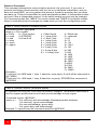
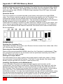
Power Up Initial Display
When powering on, the Caretaker Plus goes through a power up self-test which checks
the main functions of its electronics. The leftmost LED labeled POWER should glow
green and the other red LEDs should all turn on. Then the unit will cycle through four
tests lighting up LEDs 1 through 4 as each test is performed. Errors are indicated by the
ERROR LED lighting and the unit halting. See TABLE 6 for the full sequence of the
power up LED display and TABLE 7 for error displays.
Table 6. LED Power Up Display
Legend: M = Mode LED
D = Data LED
B = Busy LED E = Error LED
● = LED on
O = LED off
X = may vary, described below
M D B
E
1
st
● ● ● ●
2
nd
O O O O
3
rd
O O O O
1
2
3
4
5
☼ = LED flashing
6
7
8
4
th
O O O O
5
th
O O O O
● ● ● ● ● ● ● ●
● O O O O O O O
O ● O O O O O O
O ● O O O O O ●
O ● O O O O ● ●
O ● O O O ● ● ●
O ● O O ● ● ● ●
O ● O ● ● ● ● ●
O O ● O O O O O
O O O ● O O O O
6
th
O O O O
O O O O O O O O
O O O O
O O O O
O O O O
O O O O
O O O O
EXPLANATION
All LEDs on
Test 1: EPROM checker
Test 2: 16K RAM buffer
Test 2: 64K RAM buffer
Test 2: 256K RAM buffer
Test 2: 512K RAM buffer
Test 2: 1M RAM buffer
Test 2: 2M RAM buffer
Test 3: Static RAM
Non-volatile RAM
Unit ready
NOTE: The BUSY LED may be lit when the unit enters the ready state. This is
dependent upon the state of the shared device.
Program Checksum Test
This test verifies that the unit's internal program is valid by performing a checksum test.
If a fault exists, a program checksum error shows on the LEDs as error 1, as shown in
TABLE 7. The unit will immediately halt. This error requires that the unit be serviced.
Buffer Memory Sizing and Read/Write Test
In this test, the Caretaker Plus automatically determines amount of buffer memory
present and indicates the amount via the status LEDs as shown in TABLE a. The buffer
memory is then tested to ensure that the memory system is operational. Any failure will
cause the error 2 condition to be displayed, as shown in TABLE 7, indicating that a
buffer memory data error has occurred. The unit will not continue its further tests and will
halt. An error indicates that the unit requires servicing.
20
CARETAKER PLUS INSTALLATION AND OPERATIONS MANUAL