1
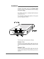
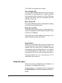
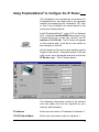
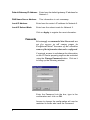
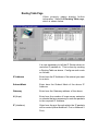
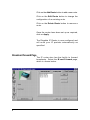
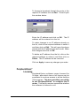
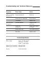
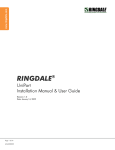
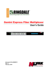
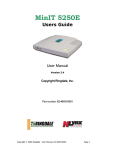
Contents
Introduction
2
Installation
3
Using PeripheralVision®
to Configure the IP Router
5
IP Router Page
Passwords
Routing Table Page
Broadcast Forward Page
PeripheralVision® Licensing
5
6
7
8
9
Safety and Location Advice
10
Troubleshooting and
Technical Reference
11
Technical Support
12
1
Introduction
The Ringdale IP Router is a local two port
Ethernet IP router which enables IP packets to
be routed from one Network/Subnet to another
on your Local or Wide Area Network, and even
across the Internet if required.
The IP Router is simple to install and can be
configured and remotely managed using the
PeripheralVision software provided.
®
Use PeripheralVision to create a routing table
which directs the IP packets straight to the
required IP Address, giving greater control over
the operation of the network and aiding the
speedy transmission of data.
®
Follow the instructions in this guide for quick
installation and operation of your Ringdale IP
Router.
Features
Remote management through Ringdale’s
PeripheralVision® software
Supports multiple IP Addresses on the same
network
Broadcast Forwarding
Integral all voltage power supply
Extremely low power consumption (3 watts)
Flash Upgradable
2
Installation
Connect the power cord to the Power Input
socket as shown in the illustration below and plug
into power supply.
The LEDs will flash to indicate that the device
has powered up.
The illustration shows the position of the ports
and the diagnostic LEDs.
The two ports are itemized as follows:
Network 1 Port
Connect to this port the RJ45 cable from the hub
of the first network/Subnet Mask you wish to route
to.
Network 2 Port
Connect to this port the RJ45 cable from the hub
of the second network/ Subnet Mask you wish to
route to.
3
The LEDs are itemized as follows:
Link (Yellow) LED
The Link LED indicates that the port is functionally
connected to an external port. It lights up when
the connected hub is turned on. If the LED does
not light up, there may be a problem with the
cabling or the hub.
Write (Red) LED
The write LED blinks when a data packet is being
sent from that particular port.
Read (Green) LED
The Read LED blinks when a data packet is
received, regardless of the status of the port, even
if the port is disabled.
These last two LEDs enable monitoring of the
traffic passing through the device.
Reset Button
When this is pressed the router will clear the
routing table of the surplus information it is
holding, but will retain the IP address settings
last entered with PeripheralVision (for details
on PeripheralVision and how it is used to
configure the IP router, see the following section).
®
®
Pressing Reset will not reconfigure the IP
addresses you have set.
Setup Procedure
Once the router is installed on the network it is
necessary to configure the device.
Configuration is accomplished by using the
PeripheralVision software supplied with the IP
router.
®
4
Using PeripheralVision® to Configure the IP Router
Full Installation and operational procedures for
PeripheralVision are dealt with in the separate
manual accompanying the Installation CD, refer
to this if any problems are encountered in the
procedure detailed below.
®
11.22.33.44
Install PeripheralVision® onto a PC on Network
One. Using the Locate NPMPTM discovery tool in
PeripheralVision ® , enter the default set IP
address (11.22.33.44). The IP router will appear
on the network map, it will be an icon similar to
the example on the left.
Left click twice on the icon to open up the property
Pages of the device. Using the arrows in the top
right corner, scroll the pages and click on the first
IP Router page. This is shown below.
The following information needs to be entered
onto this page (this will be supplied by your
network administrator).
IP Address
Enter here the router’s IP address for Network 1.
TCP/IP Subnet Mask
Enter here the subnet mask for Network 1.
5
Default Gateway IP Address
Enter here the default gateway IP address for
Network 1.
DNS Name Server Address
This information is not necessary.
Local IP Address
Enter here the router’s IP address for Network 2.
Local IP Subnet Mask
Enter here the subnet mask for Network 2.
Click on Apply to register the new information.
Passwords
It is strongly recommended that Passwords are
set for access to all router pages in
PeripheralVision ® because of the sensitive
nature of the information that can be configured.
If required, access to set/change the information
on the IP Router property page can be restricted
using the Change Password button. Click on it
to bring up the following window.
Enter the Password into the box, type in the
confirmation and click on OK.
Access to change the configuration will now be
restricted to those who have the Password.
6
Routing Table Page
Other property pages display further
information. Select the Routing Table page,
which is shown below.
It is now necessary to tell the IP Router where to
route the IP packets to. This is done by creating
a Routing Table as above. Configure each route
as follows.
IP Address
Enter here the IP Address of the subnet you want
to route to.
Subnet Mask
Enter here the Subnet Mask of the above IP
Address.
Gateway
Enter here the Gateway address of the above.
H (Hops)
Enter here the number of hops across networks
or subnets that are necessary to route the packets
to the required IP Address.
IF (Interface)
Enter here the port through which the IP packets
will be routed (either Network 1 Port or Network 2
Port).
7
Click on the Add Route button to add a new route.
Click on the Edit Route button to change the
configuration of an existing route.
Click on the Delete Route button to remove a
route.
Once the routes have been set up as required,
click on Apply.
The Ringdale IP Router is now configured and
will route your IP packets automatically as
specified.
Broadcast Forward Page
The IP router also has the facility to forward
broadcasts. Select the B’cast Forward page,
which is shown below:
8
To forward a broadcast through the router to the
required IP address click on Add. This will open
the window below:
Enter the IP address and click on OK. The IP
address will be entered into the list.
To make changes to an IP address already on
the list, click on the required address to select it
and then click on Edit. This will open the above
window with the IP address you wish to edit. Make
the changes and click on OK.
To delete an IP address from the list, click on the
required address to select it and then click on
Delete. The IP address will be removed.
Click on Apply to save any changes you make.
PeripheralVision®
Licensing
PeripheralVision® software comes licenced for
30 days, after which time a full licence can be
purchased to continue access to all the facilities
of the program. This does not affect your ability
to use PeripheralVision® to configure the IP
router. This facility remains operational whether
the software is licenced or not.
9
Safety and Location Advice
The device is designed to operate in a typical
office environment. Choose a site that is:
Well ventilated and away from sources of heat
including direct sunlight.
Away from sources of vibration or physical
shock.
Isolated from strong electromagnetic fields
produced by electrical devices.
Provided with a properly grounded wall outlet.
Do not attempt to modify or use the supplied
AC power cord if it is not the exact type
required.
Ensure that the system is disconnected from
its
power
source
and
from
all
telecommunications links, networks, or
modem lines whenever the chassis cover is
to be removed. Do not operate the system
with the cover removed.
10
Troubleshooting and Technical Reference
Symptom
Poss. Cause
Action
LEDs do not flash
at power-up
Power switched off
Switch on
Power cord not connected
Plug in Router
Fuse defect
Replace fuse
No cable inserted
Connect to hub
and Router
Router not
powered up
Check power supply
for Router
Wrong cable type
Verify cable selection
Bad cable
Replace cable
Link LED does
not light up
Technical Specification
Mains supply:
Input: 90..240 volts AC
Frequency: 50..60Hz
Power: 3 watts typical
Network One Connection: Ethernet RJ45
Network Two Connection: Ethernet RJ45
Part No:
00-02-0342-0050
11
Technical Support
Ringdale Ltd, Ringdale Inc. and Ringdale GmbH
all have Technical Support Departments. Their
addresses and contact details are found on the
back cover of this manual.
Before you call:
Please have the following information ready before calling:
Type of adapters installed in the System.
The adapter settings and interrupt options.
Network Information:
Network operating system type and version,
server configuration.
LAN topology:
Type of cable being used, size of network, number
of PCs and other nodes in network.
Computer Information:
Manufacturer, model number, operating system
used on the computer.
History of the Problem:
The symptoms of the problem.
Did the device work for a period of time or fail
immediately after installation?
Was any PC option changed (hardware or
software) prior to the problem appearing?
12