1
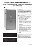
OP--620 Operator Panel Manual Number OP--620--M WARNING Thank you for purchasing automation equipment from PLCDirect. We want your new DirectLOGIC automation equipment to operate safely. Anyone who installs or uses this equipment should read this publication (and any other relevant publications) before installing or operating the equipment. To minimize the risk of potential safety problems, you should follow all applicable local and national codes that regulate the installation and operation of your equipment. These codes vary from area to area and usually change with time. It is your responsibility to determine which codes should be followed, and to verify that the equipment, installation, and operation is in compliance with the latest revision of these codes. At a minimum, you should follow all applicable sections of the National Fire Code, National Electrical Code, and the codes of the National Electrical Manufacturer’s Association (NEMA). There may be local regulatory or government offices that can also help determine which codes and standards are necessary for safe installation and operation. Equipment damage or serious injury to personnel can result from the failure to follow all applicable codes and standards. We do not guarantee the products described in this publication are suitable for your particular application, nor do we assume any responsibility for your product design, installation, or operation. If you have any questions concerning the installation or operation of this equipment, or if you need additional information, please call us at 1–800–633–0405. This publication is based on information that was available at the time it was printed. At PLCDirect we constantly strive to improve our products and services, so we reserve the right to make changes to the products and/or publications at any time without notice and without any obligation. This publication may also discuss features that may not be available in certain revisions of the product. Trademarks This publication may contain references to products produced and/or offered by other companies. The product and company names may be trademarked and are the sole property of their respective owners. PLCDirect disclaims any proprietary interest in the marks and names of others. Stage is a trademark of Koyo Electronics Industries Co., LTD. Texas Instruments is a registered trademark of Texas Instruments, Inc. TI, TIWAY, Series 305, Series 405, TI305, and TI405 are trademarks of Texas Instruments, Inc. Siemens and SIMATIC are registered trademarks of Siemens, AG. GE is a registered trademark of General Electric Corporation. Series One is a registered trademark of GE Fanuc Automation North America, Inc. MODBUS is a registered trademark of Gould, Inc. IBM is a registered trademark of International Business Machines. MS-DOS and Microsoft are registered trademarks of Microsoft Corporation. Windows is a trademark of Microsoft Corporation. OPTOMUX and PAMUX are trademarks of OPTO 22. Copyright 1998, PLCDirect Incorporated All Rights Reserved No part of this manual shall be copied, reproduced, or transmitted in any way without the prior, written consent of PLCDirect Incorporated. PLCDirect retains the exclusive rights to all information included in this document. 1 Manual Revisions If you contact us in reference to this manual, be sure and include the revision number. Title: OP–620 Operator Panel User Manual Manual Number: OP–620–M Issue Date Original 8/97 Rev A 6/98 Effective Pages Cover/Copyright Contents Description of Changes Original Issue Made minor revisions before reprinting 1 Table of Contents i Introduction . . . . . . . . . . . . . . . . . . . . . . . . . . . . . . . . . . . . . . . . . . . . . . . . . . . . . . . . . . . . . . . . . . . . . . . . . OP-620 Operator Panel . . . . . . . . . . . . . . . . . . . . . . . . . . . . . . . . . . . . . . . . . . . . . . . . . . . . . . . . . . . . . . . Introduction . . . . . . . . . . . . . . . . . . . . . . . . . . . . . . . . . . . . . . . . . . . . . . . . . . . . . . . . . . . . . . . . . . . . . . . Applications . . . . . . . . . . . . . . . . . . . . . . . . . . . . . . . . . . . . . . . . . . . . . . . . . . . . . . . . . . . . . . . . . . . . . . . Features . . . . . . . . . . . . . . . . . . . . . . . . . . . . . . . . . . . . . . . . . . . . . . . . . . . . . . . . . . . . . . . . . . . . . . . . . . Configuration Options . . . . . . . . . . . . . . . . . . . . . . . . . . . . . . . . . . . . . . . . . . . . . . . . . . . . . . . . . . . . . . . . PLC Stand Alone . . . . . . . . . . . . . . . . . . . . . . . . . . . . . . . . . . . . . . . . . . . . . . . . . . . . . . . . . . . . . . . . . . . PLC Multi Panels . . . . . . . . . . . . . . . . . . . . . . . . . . . . . . . . . . . . . . . . . . . . . . . . . . . . . . . . . . . . . . . . . . . Use With A PLC . . . . . . . . . . . . . . . . . . . . . . . . . . . . . . . . . . . . . . . . . . . . . . . . . . . . . . . . . . . . . . . . . . . . . . Memory Mapping . . . . . . . . . . . . . . . . . . . . . . . . . . . . . . . . . . . . . . . . . . . . . . . . . . . . . . . . . . . . . . . . . . Register Definition . . . . . . . . . . . . . . . . . . . . . . . . . . . . . . . . . . . . . . . . . . . . . . . . . . . . . . . . . . . . . . . . . . Operational Overview . . . . . . . . . . . . . . . . . . . . . . . . . . . . . . . . . . . . . . . . . . . . . . . . . . . . . . . . . . . . . . . Displaying Messages on the LCD Display . . . . . . . . . . . . . . . . . . . . . . . . . . . . . . . . . . . . . . . . . . . . . Placing Numeric Data in the Display . . . . . . . . . . . . . . . . . . . . . . . . . . . . . . . . . . . . . . . . . . . . . . . . . . Displaying Data with a Decimal Point . . . . . . . . . . . . . . . . . . . . . . . . . . . . . . . . . . . . . . . . . . . . . . . . . Displaying Fixed Point Numbers . . . . . . . . . . . . . . . . . . . . . . . . . . . . . . . . . . . . . . . . . . . . . . . . . . . . . Displaying BCD and Binary Numbers . . . . . . . . . . . . . . . . . . . . . . . . . . . . . . . . . . . . . . . . . . . . . . . . . Displaying “Double Numbers” . . . . . . . . . . . . . . . . . . . . . . . . . . . . . . . . . . . . . . . . . . . . . . . . . . . . . . . . Displaying Floating Point Numbers . . . . . . . . . . . . . . . . . . . . . . . . . . . . . . . . . . . . . . . . . . . . . . . . . . . Numeric Data Entry . . . . . . . . . . . . . . . . . . . . . . . . . . . . . . . . . . . . . . . . . . . . . . . . . . . . . . . . . . . . . . . . Data Entry/Adjustment with the Arrow Keys . . . . . . . . . . . . . . . . . . . . . . . . . . . . . . . . . . . . . . . . . . . . Example of Arrow Adjustment of Numeric Data . . . . . . . . . . . . . . . . . . . . . . . . . . . . . . . . . . . . . . . . Function Buttons . . . . . . . . . . . . . . . . . . . . . . . . . . . . . . . . . . . . . . . . . . . . . . . . . . . . . . . . . . . . . . . . . . . Menu Tree Operation . . . . . . . . . . . . . . . . . . . . . . . . . . . . . . . . . . . . . . . . . . . . . . . . . . . . . . . . . . . . . . . Configuration . . . . . . . . . . . . . . . . . . . . . . . . . . . . . . . . . . . . . . . . . . . . . . . . . . . . . . . . . . . . . . . . . . . . . . Examples of Use with A PLCDirect PLC . . . . . . . . . . . . . . . . . . . . . . . . . . . . . . . . . . . . . . . . . . . . . . . . Register Usage . . . . . . . . . . . . . . . . . . . . . . . . . . . . . . . . . . . . . . . . . . . . . . . . . . . . . . . . . . . . . . . . . . . . Using a Function Button . . . . . . . . . . . . . . . . . . . . . . . . . . . . . . . . . . . . . . . . . . . . . . . . . . . . . . . . . . . . . Displaying Messages on the LCD Display . . . . . . . . . . . . . . . . . . . . . . . . . . . . . . . . . . . . . . . . . . . . . Displaying Long BCD Numbers . . . . . . . . . . . . . . . . . . . . . . . . . . . . . . . . . . . . . . . . . . . . . . . . . . . . . . Displaying Floating Point Numbers . . . . . . . . . . . . . . . . . . . . . . . . . . . . . . . . . . . . . . . . . . . . . . . . . . . Arrow Adjustment of Setpoint Data . . . . . . . . . . . . . . . . . . . . . . . . . . . . . . . . . . . . . . . . . . . . . . . . . . . Using a Menu Tree . . . . . . . . . . . . . . . . . . . . . . . . . . . . . . . . . . . . . . . . . . . . . . . . . . . . . . . . . . . . . . . . . A Menu Tree Example . . . . . . . . . . . . . . . . . . . . . . . . . . . . . . . . . . . . . . . . . . . . . . . . . . . . . . . . . . . . . . Examples of Use with an Allen-Bradley PLC . . . . . . . . . . . . . . . . . . . . . . . . . . . . . . . . . . . . . . . . . . . . Interfacing to A-B Memory . . . . . . . . . . . . . . . . . . . . . . . . . . . . . . . . . . . . . . . . . . . . . . . . . . . . . . . . . . . Using a Function Button . . . . . . . . . . . . . . . . . . . . . . . . . . . . . . . . . . . . . . . . . . . . . . . . . . . . . . . . . . . . . Displaying Floating Point Numbers . . . . . . . . . . . . . . . . . . . . . . . . . . . . . . . . . . . . . . . . . . . . . . . . . . . Displaying Messages on the LCD Display . . . . . . . . . . . . . . . . . . . . . . . . . . . . . . . . . . . . . . . . . . . . . Displaying Long BCD Numbers . . . . . . . . . . . . . . . . . . . . . . . . . . . . . . . . . . . . . . . . . . . . . . . . . . . . . . Arrow Adjustment of Setpoint Data . . . . . . . . . . . . . . . . . . . . . . . . . . . . . . . . . . . . . . . . . . . . . . . . . . . Using a Menu Tree . . . . . . . . . . . . . . . . . . . . . . . . . . . . . . . . . . . . . . . . . . . . . . . . . . . . . . . . . . . . . . . . . A Menu Tree Example . . . . . . . . . . . . . . . . . . . . . . . . . . . . . . . . . . . . . . . . . . . . . . . . . . . . . . . . . . . . . . Setup and Interconnect . . . . . . . . . . . . . . . . . . . . . . . . . . . . . . . . . . . . . . . . . . . . . . . . . . . . . . . . . . . . . . . Legending the Function Keys . . . . . . . . . . . . . . . . . . . . . . . . . . . . . . . . . . . . . . . . . . . . . . . . . . . . . . . . Connection to the System . . . . . . . . . . . . . . . . . . . . . . . . . . . . . . . . . . . . . . . . . . . . . . . . . . . . . . . . . . . * 1 1 1 1 2 2 2 3 3 3 4 4 4 4 4 4 4 4 5 5 5 6 6 6 7 7 7 8 9 9 10 11 12 14 14 14 14 15 16 16 17 18 20 20 21 Table of Contents Connections to a Computer or PLC . . . . . . . . . . . . . . . . . . . . . . . . . . . . . . . . . . . . . . . . . . . . . . . . . . . Serial Connection to OP-9001 Communications Master . . . . . . . . . . . . . . . . . . . . . . . . . . . . . . . . . Termination . . . . . . . . . . . . . . . . . . . . . . . . . . . . . . . . . . . . . . . . . . . . . . . . . . . . . . . . . . . . . . . . . . . . . . . . Power . . . . . . . . . . . . . . . . . . . . . . . . . . . . . . . . . . . . . . . . . . . . . . . . . . . . . . . . . . . . . . . . . . . . . . . . . . . . Configuration . . . . . . . . . . . . . . . . . . . . . . . . . . . . . . . . . . . . . . . . . . . . . . . . . . . . . . . . . . . . . . . . . . . . . . . . Configuration Selections . . . . . . . . . . . . . . . . . . . . . . . . . . . . . . . . . . . . . . . . . . . . . . . . . . . . . . . . . . . . Single Module PLC Based Systems . . . . . . . . . . . . . . . . . . . . . . . . . . . . . . . . . . . . . . . . . . . . . . . . . . Multi Module PLC Applications (Uses Communications Master) . . . . . . . . . . . . . . . . . . . . . . . . . . Creating Messages . . . . . . . . . . . . . . . . . . . . . . . . . . . . . . . . . . . . . . . . . . . . . . . . . . . . . . . . . . . . . . . . . Label and Message Definition Templates . . . . . . . . . . . . . . . . . . . . . . . . . . . . . . . . . . . . . . . . . . . . . . . Specifications . . . . . . . . . . . . . . . . . . . . . . . . . . . . . . . . . . . . . . . . . . . . . . . . . . . . . . . . . . . . . . . . . . . . . . . . Physical . . . . . . . . . . . . . . . . . . . . . . . . . . . . . . . . . . . . . . . . . . . . . . . . . . . . . . . . . . . . . . . . . . . . . . . . . . Electrical . . . . . . . . . . . . . . . . . . . . . . . . . . . . . . . . . . . . . . . . . . . . . . . . . . . . . . . . . . . . . . . . . . . . . . . . . . Communication . . . . . . . . . . . . . . . . . . . . . . . . . . . . . . . . . . . . . . . . . . . . . . . . . . . . . . . . . . . . . . . . . . . . Communication Failure Operation . . . . . . . . . . . . . . . . . . . . . . . . . . . . . . . . . . . . . . . . . . . . . . . . . . . . Panel Mounting Dimensions . . . . . . . . . . . . . . . . . . . . . . . . . . . . . . . . . . . . . . . . . . . . . . . . . . . . . . . . . Appendix A, Example Programs . . . . . . . . . . . . . . . . . . . . . . . . . . . . . . . . . . . . . . . . . . . . . . . . . . . . . . . Understanding the Example Programs . . . . . . . . . . . . . . . . . . . . . . . . . . . . . . . . . . . . . . . . . . . . . . . . Software Requirements . . . . . . . . . . . . . . . . . . . . . . . . . . . . . . . . . . . . . . . . . . . . . . . . . . . . . . . . . . . . . 9 Steps to Using the Example Programs . . . . . . . . . . . . . . . . . . . . . . . . . . . . . . . . . . . . . . . . . . . . . . Step 1: Power Supply Connections . . . . . . . . . . . . . . . . . . . . . . . . . . . . . . . . . . . . . . . . . . . . . . . . . . . Step 1A: Multi-Panel Power Supply Connections (Optional) . . . . . . . . . . . . . . . . . . . . . . . . . . . . . . Step 2: Selecting Configuration Mode: Setting the OP-Panel DIP Switches . . . . . . . . . . . . . . . . Step 3: Selecting Cables . . . . . . . . . . . . . . . . . . . . . . . . . . . . . . . . . . . . . . . . . . . . . . . . . . . . . . . . . . . . Choosing Your Connecting Cables . . . . . . . . . . . . . . . . . . . . . . . . . . . . . . . . . . . . . . . . . . . . . . . . . . . Connecting Cable Details . . . . . . . . . . . . . . . . . . . . . . . . . . . . . . . . . . . . . . . . . . . . . . . . . . . . . . . . . . . Step 4: Connecting Configuration Cable OP–ACBL–1 . . . . . . . . . . . . . . . . . . . . . . . . . . . . . . . . . . . Step 5: Installing Example Programs on Your Personal Computer Hard Drive . . . . . . . . . . . . . . Step 6: Loading OP-WINEDIT Example Program into the OP-Panel . . . . . . . . . . . . . . . . . . . . . . Step 7: Setting the OP-Panel DIP Switch Positions for Program/Run Mode . . . . . . . . . . . . . . . . Step 8: Loading DirectSOFT Example Program into the PLC . . . . . . . . . . . . . . . . . . . . . . . . . . . . Step 9: Connecting the OP-Panel to the PLC and Running the Program . . . . . . . . . . . . . . . . . . Running the OP-620 Example Program . . . . . . . . . . . . . . . . . . . . . . . . . . . . . . . . . . . . . . . . . . . . . . . Kiln Demo Example Worksheet . . . . . . . . . . . . . . . . . . . . . . . . . . . . . . . . . . . . . . . . . . . . . . . . . . . . . . Example Message Worksheet . . . . . . . . . . . . . . . . . . . . . . . . . . . . . . . . . . . . . . . . . . . . . . . . . . . . . . . Example Menu Worksheet . . . . . . . . . . . . . . . . . . . . . . . . . . . . . . . . . . . . . . . . . . . . . . . . . . . . . . . . . . OP-620 Application Worksheet . . . . . . . . . . . . . . . . . . . . . . . . . . . . . . . . . . . . . . . . . . . . . . . . . . . . . . . OP-620 Message Worksheet . . . . . . . . . . . . . . . . . . . . . . . . . . . . . . . . . . . . . . . . . . . . . . . . . . . . . . . . OP-620 Menu Worksheet . . . . . . . . . . . . . . . . . . . . . . . . . . . . . . . . . . . . . . . . . . . . . . . . . . . . . . . . . . . OP-9001 Multi-Panel Configurations . . . . . . . . . . . . . . . . . . . . . . . . . . . . . . . . . . . . . . . . . . . . . . . . . . Appendix B, Troubleshooting the OP-620 . . . . . . . . . . . . . . . . . . . . . . . . . . . . . . . . . . . . . . . . . . . . . . Troubleshooting the OP-620 Panel . . . . . . . . . . . . . . . . . . . . . . . . . . . . . . . . . . . . . . . . . . . . . . . . . . . Troubleshooting . . . . . . . . . . . . . . . . . . . . . . . . . . . . . . . . . . . . . . . . . . . . . . . . . . . . . . . . . . . . . . . . . . . . Panel Configuration Problems . . . . . . . . . . . . . . . . . . . . . . . . . . . . . . . . . . . . . . . . . . . . . . . . . . . . . . . Panel to PLC Communications Problems . . . . . . . . . . . . . . . . . . . . . . . . . . . . . . . . . . . . . . . . . . . . . . Allen-Bradley Panel to PLC Communications Problems . . . . . . . . . . . . . . . . . . . . . . . . . . . . . . . . . ii 21 21 21 21 22 22 22 22 23 24 25 25 25 25 25 25 A-1 A-2 A-2 A-3 A-3 A-4 A-5 A-5 A-6 A-7 A-8 A-8 A-9 A-10 A-10 A-10 A-11 A-16 A-17 A-18 A-19 A-20 A-21 A-22 B-1 B-2 B-2 B-2 B-3 B-4 1 EU Information This product is manufactured in compliance with European Union (EU) Directives and carries the CE mark. The following information is provided to comply with EU documentation requirements. NOTE: Products with CE marks perform their required functions safely and adhere to relevant standards as specified by EC directives provided they are used according to their intended purpose and that the instructions in this manual are adhered to. The protection provided by the equipment may be impaired if this equipment is used in a manner not specified in this manual. Only replacement parts supplied by PLCDirect or its agents should be used. A listing of international affiliates is available at our Web site http://www.plcdirect.com Technical Support If you need technical assistance, please call the technical support group at PLCDirect (3505 Hutchinson Rd., Cumming, GA 30040, U.S.A.) at 800--633--0405. They are available Monday through Friday from 9:00 A.M. to 6:00 P.M. Eastern Standard Time. Their Web Site address is http://www.plcdirect.com SELV Circuits All electrical circuits connected to the communications port receptacle are rated as Safety Extra Low Voltage (SELV). Environmental Specifications Operating Temperature . . . . . . . . . . . . . . . . . . . . . 0° to 50° C Storage Temperature . . . . . . . . . . . . . . . . . . . . . . --20° to 70° C Operating Humidity . . . . . . . . . . . . . . . . . . . . . . . . 95% (non-condensing) Air Composition . . . . . . . . . . . . . . . . . . . . . . . . . . . No corrosive gases permitted Preventative Maintenance and Cleaning No preventative maintenance is required. To clean the exterior of the panel disconnect the input power and carefully wipe the panel with a cloth moistened with plain water. External Fuse Protection for Input Power There are no internal fuses for the input power circuits, so external circuit protection is needed to ensure the safety of service personnel and the safe operation of the equipment itself. To comply with EU specifications, the input power must be fused. Use a fuse rated at twice the input current rating of the panel. For example, if the panel has an input current rating of 0.5 amperes, use a fuse rated for 1 ampere. Installing and Using the Example Programs The Purpose of this Manual This User Manual provides user information on panel installation, panel configuration, and programming the OP-620. The purpose of this manual is to teach programming techniques which may be applied while implementing the OptiMater panels. After reading the manual completely, load and run the example programs which are on the supplied diskette using the directions in Appendix A. Contents of the Manual Inside this manual you will learn about planning, implementing, and utilizing the OptiMate OP-620 panel. Also included are application examples to improve the learning process and working knowledge of the OptiMate units. How to Use the OP-620 The OPĆ1500 and OPĆ1510 Operator panels may be reconfigured to exchange data with your programmable controller. Supplemental Manuals Reference the appropriate PLC/CPU User Manuals for the commands and address references required for your system. If you are using a DirectLOGIC PLC product, you will want to keep the DirectSOFT User Manual handy while programming your system. For other PLC brands you must reference their User manuals to properly program the ladder logic required to operate the OP-panels. For Multi-Panel applications utilizing the OP-9001 Communications Master please refer to the OPĆ9001 User Manual (Part Number OP–9001–M). Technical Assistance After completely reading this manual, including Appendix B, Troubleshooting the OP-620, if you are not successful with implementing the OP-620, you may call PLCDirect at (800) 633-0405, Monday through Friday from 9:00 A.M. to 6:00 P.M. Eastern Standard Time. Our technical support group will work with you in answering your application questions. If you have a comment or question about our products, services, or manuals which we provide, please fill out and return the suggestions card included with this manual. Appendix B ASCII to HEX Cross Ref. Introduction Appendix A Example Programs 1A Installing and Using the Example Programs Appendix B ASCII to HEX Cross Ref. Understanding the One of the best ways to learn how to use the OP-panel is to load the example Example Programs programs which are on the supplied diskette, and run the program for your PLC. A Cement Kiln System is used to demonstrate the ladder logic required to support the various OP-panel features. The program provides ladder logic which demonstrates controlling pushbuttons, lamps, messages and menu operations. Use an understanding of this example program to help develop programs for your own applications. Follow the instructions in this chapter for installing and running the example programs. Software Requirements The example programs require that you have two software packages loaded on your personal computer: S DirectSOFT programming software, and S OP-WINEDIT (OptiMate Editor) configuration software. If you do not have these software packages, obtain and install them on your personal computer using the instructions in their user manuals. Once you have both programs installed on your personal computer you are ready to use the following step-by-step instructions for installing and using the example programs. Page A–2 Installing and Using the Example Programs 9 Steps to Using the Example Programs SOFT OPĆWINEDIT Pushbuttons... Memory Requirements... Process Data..... Fault messages.... CLEAR/ ABORT MENU ENTER Example Programs Step 1: Power Supply Connections An external power supply should be used to power the Optimation unit. The power supply must supply a voltage of 8 to 30 VDC. Connect the power supply using the supplied terminal block connector. The connector is keyed to prevent reversing the polarity. Pin 1 is the positive connection (8 to 30VDC), while pin 2 is the common (0VDC) or ground connection. Use 18–24 AWG conductor wire and connect the power supply to the supplied connector block as follows: Connect the positive (+8 to 30 VDC) lead to terminal 1, and connect the common ground (0V) lead to terminal 2. Receptacle Terminal 2 1 Terminal 1 Ground +24VDC Plug the terminal block connector into Power receptacle located on the back side of the panel. Page A–3 2 Installing and Using the Example Programs Step 1A: Multi-Panel Power Supply Connections (Optional) In multi-panel applications, if using separate power supplies, make sure the electrical ground commons do not have a great potential difference. When using a single power supply in a multi-panel application, the power supply must maintain the specified voltage and current consumption for each of the individual units under all conditions (including power-up). See individual panel power requirements. (Communications to PLC) + OP-9001 Power Supply J1 J2 (RS-422) Panel 1 Power Supply Page A–4 Panel 3 Panel 2 Power Supply Power Supply Installing and Using the Example Programs Step 2: Setting the OP-Panel PGM/RUN DIP Switch to PGM You may generate your OP-panel configuration off-line. To download your configuration, the PGM/RUN DIP switch located on the back of the OP-panel must be set to PGM (ON). The TERM switch should remain off. NOTE: You must cycle power to the panel (turn power off, set DIP switch, and turn power back on) to activate the new switch settings. RUN Step 3: Selecting Cables 1 2 ON PGM TERM Set to PGM For multi-panel configurations, see the section titled OP-9001 Multi-Panel Configurations towards the end of this chapter. Depending on which PLC you are using, you may require as many as three cables to use the example programs: S S S An OP–ACBL–1 configuration cable to connect your personal computer to the OP-panel to load the configuration program into the panel. All panels use the OP–ACBL–1 for the configuration cable. This cable is also used to connect an OP-panel to an Allen-Bradley SLC 500 CPU. A cable to connect your personal computer to the PLC to load the DirectSOFT example ladder programs into your PLC. See the DirectSOFT user manual for help in selecting the proper cable to use with your PLC. A cable to connect the OP-panel to the PLC. Use the information on the next two pages to select the proper cable to use with your PLC. Page A–5 Installing and Using the Example Programs Choosing Your Connecting Cables Depending on which PLC you are using, you may require as many as two cables. Here are the requirements: D OP-ACBL-1: all units require this cable for configuration. This is a 9-pin female to 15-pin male cable that connects your personal computer to the OP-panel. This cable is also used to connect an OP-panel to the Allen-Bradley SLC 500 CPUs listed. D CPU Cables: You will also need the appropriate cable to connect your CPU to the OP-panel. Use the chart shown to the right to choose the correct communications cable. OP-9001 Cable Connectors OptiMate Cables Family CPU (or other device) D D D OP-CMCON–1 — pack of 4 ribbon cable connectors. OP-CMCON–2 — pack of 4 solder-type connectors. OP-CMCON–3 — pack of 2 D–shell connectors with screw terminals for use with OPĆ9001 & multiple OP-panels. OP-PSCON — pack of 4 power supply block connectors. For electrically noisy environments, we recommend an individually paired and shielded cable, such as Belden 9729 or equivalent. This type of cable requires the solder-type or D-shell with screw terminal connectors. For distance of 30 feet or less, you can use ribbon cable. For ribbon cable, we recommend Belden 9L28015 or 3M 3365/15. * — requires RS232 Data Communications Unit (D3–232–DCU) **– also DC versions Cable DirectLOGICt DL105 DL130 Only port OP–2CBL DirectLOGICt DL205 DL230 Only port OP–2CBL DL240 Top port OP–2CBL Bottom port OP–2CBL Top port OP–2CBL Bottom port OP–2CBL–1 D2–DCM (module) Only port OP-4CBL–2 DL330 Requires DCU* OP–4CBL–2 DL330P Requires DCU* OP-4CBL–2 DL340 Top port OP-3CBL Bottom port OP-3CBL Top port OP-2CBL Bottom port OP-4CBL-2 Top port (15-pin) OP-4CBL–1 Bottom port (25-pin) OP-4CBL–2 Top port OP-4CBL–1 Bottom port OP-4CBL–2 Phone Jack OP-2CBL Top port (15-pin) OP-4CBL–1 DL250 DirectLOGICt DL305 DL350 DirectLOGICt DL405 DL430 If you’re planning to use multiple panels and an OP-9001, then you will need to build your own custom cables. Since the proper cable choice really depends on your application, we offer the following connectors. D Port DL440** DL450 GE Series 1 Bottom port (25-pin) OP-4CBL–2 D4–DCM (module) Only port OP-4CBL–2 Slice I/O panels Only port OP-4CBL–1 IC610CPU105/106 Requires DCU* OP-4CBL–2 GE Seriest 90/30 All Models (311–351) RS232, RS422 Serial Port OP-GCBL–1 GE Fanuct Series 90 Micro All Models RS232, RS422 Serial Port OP-GCBL–1 MODICON ModBus RJ45 port OP-MCBL–1 TI305t / SIMATIC TI305t 325–07, PPX:325–07 Requires DCU* OP-4CBL–2 330–37, PPX:330–37 Requires DCU* OP-4CBL–2 325S–07 (or 325 w/ Stage Kt) Requires DCU* OP-4CBL–2 330S–37, PPX:330S–37 Requires DCU* OP-4CBL–2 335–37, PPX:335–37 Phone Jacks OP-3CBL TI405t / SIMATIC TI405t If DCU is used* OP-4CBL–2 425–CPU, PPX:425–CPU ** Only port OP-4CBL–1 PPX:430–CPU Top port (15-pin) OP-4CBL–1 Bottom port (25-pin) OP-4CBL–2 Top port (15-pin) OP-4CBL–1 435–CPU, PPX:435–CPU ** Bottom port (25-pin) OP-4CBL–2 Smart Slicet I/O panels Only port OP-4CBL–1 A–B SLC 500 5/03, 5/04 Bottom port OP-ACBL–1 A-B MicroLogix Only port OP-ACBL–2 Page A–6 Installing and Using the Example Programs Connecting Cable Details Connecting Cable RJ12 (PLC) 4 3 1 DB15 3 2 5 RJ11 (PLC) 2 1 4 DB15 3 2 5 DB15 (PLC) 2 3 4 13 14 15 1 7 8 DB15 3 2 5 DB25 (PLC) 2 3 7 4 5 DB15 3 2 5 8 Pin Mini DIN DB15 7 3 4 2 2 5 The OP–620 connecting cable may vary depending on which CPU you use. Refer to the previous page to select the proper cable for connecting to your PLC. 1= 0V 2= not used 3= Din 4= Dout 5= not used 6= not used RJ12 (6P6C) RJ12 12 3 456 8= YOM 7= CTS 6= not used 5= not used 4= On-line 3= Din 2= Dout 1= YOP 13= not used 12= not used 11= not used 10= not used 9= not used 8= not used 7= 0V 6= not used 5= CTS 4= RTS 3= Din 2= Dout 1= not used 15= tied (0V) 14= tied (0V) 13= tied (0V) 12= not used 11= not used 10= not used 9= not used 4 DB15 12 DB15 DB25 Mini–DIN 5 DB15 DB15 3= Din 2= Dout 5 =0V RS-422 Pinout PLC Din + Din – Dout + Dout – 0V DB15 25= not used 24= not used 23= not used 22= not used 21= not used 20= not used 19= not used 18= not used 17= not used 16= not used 15= not used 14= not used 6 7 8 DB15 RJ11 (4P4C) 1= Din RJ11 2= Dout 3= not used 4= 0V 1 234 3 Panel 11 = Dout+ 12 = Dout – 9 = Din + 10 = Din– 5 =0V 9= not used 10= not used 11= not used 12= not used 13= not used 14= not used 15= not used RTS+ CTS+ RTS– CTS– Page A–7 1= not used 2= Dout 3= Din 4= not used 5= 0V 6= not used 7= not used 8= not used Installing and Using the Example Programs Step 4: Connecting Once the example programs are loaded in your personal computer, the first step will be to load the configuration program from the computer into the OP-panel, so make Configuration Cable OP–ACBL–1 this cable connection first. Connect the configuration cable between the serial port of the OP-panel and the serial port of the personal computer when configuring panels using the OP-WINEDIT software. The OP-WINEDIT software requires you to select the serial port number (com1, com2) being used for configuration. The figure below shows programming cable connectors and wiring specifications. Wiring diagrams refer to the cable connectors, not the communication ports. Appendix B ASCII to HEX Cross Ref. ( 1 Female DB9 3 2 5 7 8 9 5= 0V 4= not used 3= Dout 2= Din 1= not used 9=not used 8= CTS 7= RTS 6=not used 1 Male DB15 3 2 5 9= not used 10= not used 11= not used 12= not used 13= not used 14= not used 15= not used 1= not used 2= Dout 3= Din 4= not used 5= 0V 6= not used 7= not used 8= not used Step 5: Installing It is possible to load the examples from the diskette; however, we recommend copying them to the hard drive in your computer and keeping the original diskette in a the Example Programs on Your safe place. Personal Computer Hard Drive a:\filename.prj To install the example programs if using Windows 3.1, follow these steps: 1. Call up the DOS Prompt. Make a new directory on the hard drive in your computer. For example, if the hard drive is drive C and you are using an OP-620 panel, type: MD C:\OP–620 2. Copy all the files from the example program disk to the new directory. For example, if the diskette is in drive A: and the hard drive is drive C:, type: COPY A:\*.* C:\OP–620\*.* Page A–8 Installing and Using the Example Programs To install the example programs if using WIN 95, follow these steps: 1. Select the Explorer icon and open. If the hard drive is drive C, select the (C:) icon. 2. Make a new directory in the hard drive of your computer. For example, if you are using an OP-620 panel, Select the File menu, then select New and then Folder. Notice the New Folder icon that appears. Select the folder and name it “OP-620” by selecting the File menu and selecting Rename. Type in the new name. 3. Copy all the contents of the example program disk. Insert the diskette in drive A, and select and open the 3 1/2 Floppy (A) icon. Notice the disk has numerous files of example programs. Select all the programs by opening the Edit menu and selecting Select All. Open the Edit menu again and select Copy. 4. Paste the program disk contents into the new C drive “OP–620” directory. Open the “OP–620” directory, open the Edit menu and select Paste. The example programs are now loaded onto the hard drive of your computer. Remove the diskette from drive A. Step 6: Loading the The next step is to load the configuration program into the OP-panel as follows: OP–WINEDIT Example Program 1. Open the OP-WINEDIT (also called OPEditor) software. into the OP–Panel 2. When the initial screen appears, select Existing System. 3. A File Open window appears. Open the example program file that you just loaded on your hard drive (“OP-620”). A list of files appears, all having “.ocf” after the file name. These are all configuration programs. 4. Select the configuration program for the OP-panel and PLC you are using. For example, if you are using an OP-620 panel with a DL205 PLC, select and open the file titled “620_205.ocf”. 5. A screen appears having all the configuration parameters for running the example program using an OP-620 with a DL205 PLC. Make sure your OP–ACBL–1 cable is connected between your personal computer and the OP-panel, that the DIP switch slides are set to ON, and that the OP-panel power supply is on. Select Configure Panel. 6. When the next window appears, select Write to Panel. This loads the program into the OP-panel. 7. After the program is loaded, close the open windows and select Exit Software. This closes out the OP-WINEDIT software. The OP-panel is now configured, and the OP-ACBL-1 cable can be disconnected. Page A–9 Installing and Using the Example Programs Step 7: Setting the To run the example programs, set the RUN/PRG DIP switch to RUN. OP-Panel PRG/RUN DIP Switch to RUN NOTE: You must cycle power to the panel (turn power off, set DIP switch, and turn power back on) to activate new switch settings. Set to RUN RUN 1 2 ON PGM TERM Step 8: Loading the The next step is to load the DirectSOFT example program into the PLC as follows: DirectSOFT Example Program 1. Connect the communications cable from your personal computer into the PLC communications port to your PLC’s programming port on the CPU. 2. Start DirectSOFT on your personal computer. 3. Select Open Document. 4. A dialog box appears. Open the example program file that you just loaded on your hard drive (”OP-620”). A list of files appears, all having “.prj” after the file name. These are the example program files. Notice that the program files are named for the OP-panel and PLC being used and end with “.prj”. 5. Select the example program for the OP-panel and PLC you are using. For example, if you are using an OP-620 panel with a DL205 PLC, select and open the file titled “620_205.prj”. When the program opens, its ladder rungs will appear on the monitor screen. 6. Select the PLC menu, then Connect, then select the link to use. All the program examples are saved without PLC link information, so you have to re-connect to your particular CPU. If a message appears which asks you to select the source of program to view, select Disk. 7. Make sure the CPU is in Program mode. Then download the program to the CPU. One method is to select the File menu, Write Program..., then select To PLC. 8. When the program download is complete, put the CPU in Run Mode. Select the PLC menu, PLC Modes..., then select Run. The program is now running. Step 9: Connecting The next step is to connect the OP-panel to the PLC using the cable you selected the OP-Panel to the earlier. Once the OP-panel is connected to the PLC you can run the program. Read PLC and Running through the following section, Running The OP-620 Example Program, while at the same time doing the setup and actually running the program on your OP-panel. It the Program would be helpful to print a hardcopy of the example program and study the ladder logic to see how the program operates. In addition, see the Kiln Demo Worksheets at the end of this chapter to help understand the program. There are also blank worksheets to use for your own applications. Page A–10 Installing and Using the Example Programs Running the OP-620 Example Program In this example program a Cement Kiln System is used to demonstrate the ladder logic required to support the various OP-panel features. The program provides ladder logic which demonstrates controlling pushbuttons, lamps, messages and menu operations. Items listed in the figure below, such as Hopper Selection, Kiln Speed, Start/Stop/Run controls, and Kiln Zone Temperatures are monitored and controlled by the OP-panel example program. There are two parts to the program: 1. Using the “MENU” function to enter the setup parameters, and 2. Starting and stopping the program. We will discuss setup first. Use your imagination to picture the operation of the kiln system shown. The first thing we must do is the program setup. There are two main categories of setup parameters, “Raw Meal Control” and “Temperature Control”. We will discuss “Raw Meal Control” first. There are two parameters which must be setup for “Raw Meal Control”: S “Hopper Selection”: This parameter selects which hopper is going to provide the material for the kiln system. The choices are Hopper 1, Hopper 2 or Hopper 3. S “Kiln Speed”: This parameter selects the speed that the material will travel through the kiln system. The speed is specified as a percentage of the maximum possible speed and can be set for any speed between 1% (lowest speed) and 100% (highest speed). Page A–11 Installing and Using the Example Programs CLEAR/ ABORT MENU ENTER There are three parameters which must be setup for “Temperature Control”: S S S “Setpoint Zone1 Temp.”: This parameter selects the temperature that the material will be exposed to while traveling through Temperature Zone 1. The temperature can be set to any setting from 1 to 2,000, with 1 being the lowest temperature setting and 2,000 being the highest. “Setpoint Zone2 Temp.”: This parameter selects the temperature that the material will be exposed to while traveling through Temperature Zone 2 and can be set from 1 to 2,000. “Setpoint Zone3 Temp.”: This parameter selects the temperature that the material will be exposed to while traveling through Temperature Zone 3 and can be set from 1 to 2,000. Once all five parameters are setup, we are ready to run the program. This is done by pressing the F1 pushbutton. To stop the program, press F2. This is a simple program, but it shows how a program can be developed for a practical application for the OP-panel. Follow these step-by-step directions to setup the parameters and run the example program: 1. After starting the DirectSoft example program, the initial OP-panel display is: OPĆ620 KILN DEMO MENU: Setup F1: Start The first thing we want to do is setup the parameters, so press the Menu pushbutton to get the following screen: Raw Meal Control Enter/Arrow/Clear Page A–12 Installing and Using the Example Programs Press either of the up/down arrow pushbuttons (YorB) to get the following screen: Temperature Control Enter/Arrow/Clear Notice that pressing either YB pushbutton toggles the display between these two screens. These are the two main categories of setup parameters. In the second line of each screen are three choices of pushbutton selections we can make at this point: S Enter: Press this to setup the parameter currently shown. S Arrow: Press either YB pushbutton to toggle between the two screens. S Clear/Abort: Press this pushbutton to return to the initial screen. 2. Let’s setup the Raw Meal Control first, so press either YB pushbutton to get to that screen, and press Enter. The following screen appears: Hopper Selection Enter/Arrow/Clear Press Enter. The following screen appears: Meal Hopper (1Ć3): 2 Arrow UP/DOWN = 1 Select Hopper 1, 2 or 3 by using the YB pushbuttons, and pressing Enter. For example, the “2” on the top line indicates that Hopper 2 is currently selected. If we wish to change our selection to Hopper 1, press YB pushbuttons until a “1” is displayed on the bottom line, and press Enter. A “1” replaces the “2” on the top line and the display returns to the previous “Hopper Selection” screen. Pressing Clear/Abort cancels any changes made and returns the display to the initial screen. 3. Next we need to set the kiln speed. With the “Hopper Selection” screen displayed, press YB pushbuttons to get the following screen: Kiln Speed Control Enter/Arrow/Clear Page A–13 Installing and Using the Example Programs 4. Press Enter. The following screen appears: Kiln Speed (%) : 25 New Kiln Speed = 50 Select kiln speed by using the YB pushbuttons, and pressing Enter. For example, the “25” on the top line indicates that a speed of 25% of maximum speed is currently selected. If we wish to change our selection to 50% of maximum speed, press the Y pushbutton until a “50” is displayed on the bottom line, and press Enter. A “50” replaces the “25” on the top line and the display returns to the previous “Kiln Speed Control” screen. Both Raw Meal Control parameters are now set. Next we need to set the three Temperature Control parameters. 5. Press Menu and use the YB pushbuttons to select the following Temperature Control screen: Temperature Control Enter/Arrow/Clear Press Enter to get the following screen: Setpoint Zone1 Temp. Enter/Arrow/Clear First we will set the Zone 1 temperature. Press Enter to get the following screen: Zone1 Temp. SP: 100 Enter New Temp= 200 Select Zone1 temperature by using the YB pushbuttons, and pressing Enter. For example, the “100” on the top line indicates the current Zone1 temperature setting. If we wish to change our selection to “200”, press the Y pushbutton until a “200” is displayed on the bottom line, and press Enter. A “200” replaces the “100” on the top line. The Zone1 temperature is now set and the display returns to the following screen: Setpoint Zone1 Temp. Enter/Arrow/Clear Page A–14 Installing and Using the Example Programs 6. We now need to set the Zone 2 and Zone 3 temperatures in the same manner. To set the Zone 2 temperature, press the YB pushbuttons until the “Zone1” portion of the display changes to “Zone2” as follows: Setpoint Zone2 Temp. Enter/Arrow/Clear Press Enter, and set the Zone 2 temperature the same way that you set the Zone 1 temperature. Repeat the same procedure for the Zone 3 temperature. All setup parameters are now set, and you are ready to run the program. 7. After the last setup parameter is entered, press Clear/Abort to return to the following initial screen: OPĆ620 KILN DEMO MENU: Setup F1: Start To start the program, press the F1 pushbutton. Notice that the F1 indicator light momentarily lights and the screen quickly changes to the following: KILN STARTING Press F2 to Stop The above screen only appears momentarily before changing to the following: SYSTEM RUNNING Press F2 to Stop The program is now running using the parameters we preset. If you wish to stop the program, press F2. The program stops, the F2 indicator light goes on, and following screen appears: KILN SYSTEM STOPPED Press F2 to Continue Press F2 to resume running the program. You have now run through the entire example program. Print a hardcopy of the example program and study the ladder logic to see how the program operates. Hopefully this example will help you utilize the OP-panel for your own applications. Page A–15 Installing and Using the Example Programs DESCRIPTION : System Type Panel Type PUSHBUTTONS / LAMPS : A M (Alternate/Momentary) F1 Start x Stop F2 x PLC Base Register Addr Appendix B ASCII to HEX Cross Ref. F3 F4 PLC CONFIGURATION : PLC Family CPU Model F5 Protocol PLC Address PLC Timout Baud Rate Parity Data/Stop Bits Green Lamp1 System Running Yellow Lamp2 System Starting Red Lamp3 System Stopped MESSAGE: Text No. 1 No. 5 O P _ 6 2 0 K I Action: N/A Data Type/Format: Text Message M E N U : S E T U P Action: N/A Data Type/Format: Text Message K I L N S T A R T Action: N/A Data Type/Format: Text Message P R E S S F 2 T Action: N/A Data Type/Format: Text Message S Y S T E M R U N No. 6 Action: N/A Data Type/Format: N/A Text Message P R E S S F 2 T O N/A No. 7 Action: N/A Data Type/Format: Text Message K I L N S Y S T E N/A No. 8 Action: N/A Data Type/Format: Text Message P R E S S F 2 T No. 9 Action: N/A Data Type/Format: Text Message M E A L H O P P E No. 2 No. 3 No. 4 No. 10 L N N/A F D 1 : N/A I Range: N/A O S T N G N/A M O I O P Range: N/A Range: N/A S T O P Range: N/A S T O P P E D Range: N/A C O N T I N U E Range: N/A N/A R S T A R T Range: N/A N G N/A N E M O Range: N/A ( ) : Action: N/A Data Type/Format: INTEGER/BCD Range: Text Message A R R O W U P / D O W N = ^ ^ Action: Arrow Data Type/Format: BCD Range: ^ Page A–16 1 – 3 1–3 ^ Installing and Using the Example Programs MESSAGE: Text No. 11 No. 12 No.13 No.14 No. 15 No.16 No.17 No. 18 Text Message K I L N S P E E D ( % ) Action: N/A Data Type/Format: BCD Text Message N E W K I L N S P E E D Action: Keypad Data Type/Format: BCD Z O N E 1 T E M P S Action: N/A Data Type/Format: BCD P : E N T E R N E W Action: Keypad Data Type/Format: M P T E BCD Z O N E 2 T E M P S Action: N/A Data Type/Format: BCD P : E N T E R N E W Action: Keypad Data Type/Format: M P T E BCD Z O N E 3 T E M P S Action: N/A Data Type/Format: BCD P E N T E R N E W Action: Keypad Data Type/Format: M P T E BCD : : ^ ^ Range: = Range: ^ ^ . = ^ Range: ^ ^ ^ ^ Range: ^ . = ^ Range: ^ ^ N/A ^ Action: Data Type/Format: Range: Action: Data Type/Format: Range: Action: Data Type/Format: Range: Action: Data Type/Format: Range: Action: Data Type/Format: Range: Action: Data Type/Format: Range: Action: Data Type/Format: Range: Action: Data Type/Format: Range: No. No. No. No. No. No. No. No. ^ ^ N/A . = ^ Range: Range: ^ N/A ^ Data Type/Format: ^ N/A ^ ^ Range: Action: ^ N/A N/A ^ ^ Range: No. Page A–17 ^ N/A ^ N/A ^ Installing and Using the Example Programs MENU: Text No. Menu Level Appendix B ASCII to HEX Cross Ref. No. 1 2 2 4 Menu Level 1 No. Menu Level 1 No. Menu Level 1 No. Menu Level 1 No. 4 Menu Level 1 No. 3 M E Menu Level 1 2 3 3 L Function No. E R S E S P E E C Z O N E Z O Z O P O 2 4 Function No. 3 P O 2 4 Function No. 4 O I I I N N N T T T T 2 3 4 Function No. 5 2 3 4 Function No. 2 3 4 Function No. 2 3 4 Function No. 2 3 4 Function No. 2 3 4 Function No. 2 3 4 Function No. 2 3 4 Function No. 2 3 4 Function No. 2 3 4 Function No. No. Menu Level 1 No. Menu Level 1 No. Menu Level 1 No. Menu Level 1 No. Menu Level 1 No. Menu Level 1 No. Menu Level 1 No. Menu Level 1 No. Menu Level 1 I O N U R E Function No. P L T R O L Function No. 2 4 C T E C O N 2 3 L R O D E R A 3 N T P 3 C O Function No. 1 N 4 A Page A–18 T R O 1 T E M P . N E 2 T E M P . N E 3 T E M P . O N L Installing and Using the Example Programs PUSHBUTTONS / LAMPS : A M (Alternate/Momentary) DESCRIPTION : F1 System Type Panel Type F2 PLC Base Register Addr F3 F4 PLC CONFIGURATION : PLC Family CPU Model Protocol PLC Address F5 Green Lamp1 PLC Timout Yellow Lamp2 Baud Rate Parity Red Lamp3 Data/Stop Bits MESSAGE: Text Message No. Action: Data Type/Format: Range: Action: Data Type/Format: Range: Action: Data Type/Format: Range: Action: Data Type/Format: Range: Action: Data Type/Format: Range: Action: Data Type/Format: Range: Action: Data Type/Format: Range: Action: Data Type/Format: Range: Action: Data Type/Format: Range: Action: Data Type/Format: Range: No. No. No. No. No. No. No. No. No. Page A–19 Installing and Using the Example Programs MESSAGE: Text Message No. Action: Data Type/Format: Range: Action: Data Type/Format: Range: Action: Data Type/Format: Range: Action: Data Type/Format: Range: Action: Data Type/Format: Range: Action: Data Type/Format: Range: Action: Data Type/Format: Range: Action: Data Type/Format: Range: Action: Data Type/Format: Range: Action: Data Type/Format: Range: Action: Data Type/Format: Range: Action: Data Type/Format: Range: Action: Data Type/Format: Range: Action: Data Type/Format: Range: Action: Data Type/Format: Range: Action: Data Type/Format: Range: Action: Data Type/Format: Range: Appendix B ASCII to HEX Cross Ref. No. No. No. No. No. No. No. No. No. No. No. No. No. No. No. No. Page A–20 Installing and Using the Example Programs MENU: Text Message No. Menu Level 1 2 3 4 Function No. 2 3 4 Function No. 2 3 4 Function No. 2 3 4 Function No. 2 3 4 Function No. 2 3 4 Function No. 2 3 4 Function No. 2 3 4 Function No. 2 3 4 Function No. 2 3 4 Function No. 2 3 4 Function No. 2 3 4 Function No. 2 3 4 Function No. 2 3 4 Function No. 2 3 4 Function No. 2 3 4 Function No. No. Menu Level 1 No. Menu Level 1 No. Menu Level 1 No. Menu Level 1 No. Menu Level 1 No. Menu Level 1 No. Menu Level 1 No. Menu Level 1 No. Menu Level 1 No. Menu Level 1 No. Menu Level 1 No. Menu Level 1 No. Menu Level 1 No. Menu Level 1 No. Menu Level 1 Page A–21 Installing and Using the Example Programs OP-9001 Multi-Panel Configurations If you are connecting more than one OptiMate panel to a single CPU this is referred to as multi-panel configuration. MultiĆpanel configurations require the OP-9001 Communications Master, which the CPU communicates to for obtaining data from the connected OP-panels. The OP-9001 Communications Master looks for an address within the range of 0 to 30 for each panel connected. Each panel connected in a RS-422 link must have a unique address. A more detailed description of multiple panel configuration and installation is given in the OP–9001-M User Manual. The Termination Resistor The last panel must be terminated when using a RS-422 communications link by setting DIP switch 2 to the TERM (ON) position. Operator panels communicatiing more than 50 feet distance must use RS-422 and also be properly terminated. NOTE: Only the last panel of each RS-422 link should have the termination DIP switch 2 set to the TERM position. All other panels should have the DIP switch set to the off (left) position. After changing the DIP switch settings, remember to cycle power on panel to activate the new switch settings. Page A–22 Appendix B Troubleshooting the OP-620 1A Maintenance and Troubleshooting Troubleshooting the OP–620 Panel Appendix B ASCII to HEX Cross Ref. Troubleshooting In this section, we explain how to isolate potential problems which may occur while using the OPĆ620. If you are unable to troubleshoot and correct your problem using these procedures, please contact our technical product support team between the hours of 9:00 AM and 6:00 PM (EST) Monday through Friday. Call 1–800–633–0405 or fax (770) 889–7876. We have organized the troubleshooting section into two categories: S S Panel Configuration Problems Panel configuration problems Panel and PLC communications failures We explained in previous sections that the OP–WINEDIT configuration software is used to create OP-panel applications and to download and upload your OP-panel programs. If you are online with the panel and communications fails, the following error message is displayed: “Could not communicate with panel” (OP–WINEDIT ) If this occurs, check the following in the order given: 1. Check the rear panel RX/TX LEDs while attempting the Upload or Download operation. Both LEDs should be giving slow alternating flash signals, indicating the PC and OP–panel are connected. If only the TX (transmitter) LED is flashing, or if the TX/RX LEDs are not alternating between flashes, check that the OP–panel is set to the configuration mode by setting the RUN/PGM DIP switch to the PGM position. 2. Check to make sure the configuration cable (OP–ACBL–1) is properly connected. For cable details, refer to the Appendix A, Connecting the Configuration Cable OP–ACBL–1 section. 3. Make sure the correct communications port is selected with the software, such as COM1, COM2, COM3, COM4. 4. Check the 24VDC power source and connections. 5. After checking the above items, repeat the online panel Download or Upload procedure. Rear Panel View OPĆACBLĆ1 ? RX/TX LEDs Check cable connections. RUN 1 2 ON PGM TERM Page B–2 RUN/PGM DIP Switch Place the PGM/RUN switch in the PGM position when configuring the panel. TERM switch stays in the off position. Maintenance and Troubleshooting Panel to PLC Communications Problems If you experience communications difficulties between the OP-panel and PLC for a period of twelve seconds, the LEDs in the corners of the five pushbuttons will flash rapidly. In this case, you should check the following items: 1. Observe the TX and RX LEDs on the rear of the panel. Both LEDs should be a steady flash or glow (depending on baud rate). If not, check and make sure you are using the proper communications cable and that it is securely connected. 2. Examine the PGM/RUN DIP switch to make sure it is placed in the RUN position to load and run the ladder program. You must cycle OP-panel power for address switch changes to take effect. RUN 1 2 ON PGM TERM Place the PGM/RUN switch in the RUN position when running the program. 3. Examine the communications information for the proper PLC type, protocol type, baud rate, parity, stop bit, address number. Use the user manual for the PLC product you are using to determine the proper settings. 4. If you are using an OP cable, verify cable pinout. For RS422 connections use a Belden 9729 or equivalent cable. 5. Check 24VDC power source and connections. Direct LOGIC PLC DirectLOGIC PLCs : If you are using the secondary communications port such as DirectLOGIC PLC port 2, ensure the communications port address and protocol setting match. Page B–3 Maintenance and Troubleshooting PLC Model Port/Baud Rates DL105/230/240 9600 Top Parity Odd 1 Bottom Bottom (DL240 only) 9600/19.2k DL250 Top 9600 Odd/None Odd/None 1 Appendix B ASCII to HEX Cross Ref. Bottom 9600/19.2K DL330 DCU only 4800/9600/19.2k Odd/None 1 DL340 Bottom &Top 4800/9600/19.2k Odd/None 1 DL350 Top 9600 Odd 1 Bottom 4800/9600/19.2K DL430/440 Top Top 9600 Bottom 9600/19.2k DL450 Allen-Bradley Panel to PLC Communications Problems OTHER PLC Stop Bit DB15 9600 Odd Odd/None 1 Odd DB25 9600/19.2k Odd/None RJ12 9600/19.2k Odd/None 1 For Allen-Bradley, you may connect to Channel 0 (bottom serial port), using DF1 in full duplex mode. Additionally, the Allen-Bradley software allows the bottom port to a unique PLC address. The Allen-Bradley software default is PLC address one. You must ensure the OP-panel configuration address matches the PLC address you have assigned. The Allen-Bradley port only communicates using either 4800 or 9600 baud. No other baud rates are supported between the OP-panel and Allen-Bradley PLC. For example, on Allen-Bradley PLC’s the serial port baud rate defaults to 1200 baud and must be changed. The baud rate for channel 0 must be set to 4800 or 9600 baud to match the OP–WINEDIT configuration. Also the base memory area must be expanded to include the full range of registers such as N7:0 through N7:7. OTHER PLCs : Regardless of which PLC brand you are implementing, the communications parameters should be reviewed and properly configured. Please check the appropriate manual for your PLC product to ensure proper communications port and panel type settings. Page B–4