1
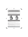
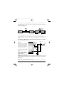
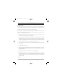
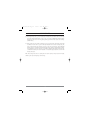
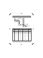
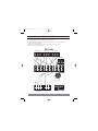
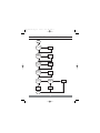
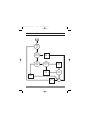
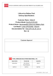
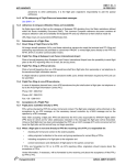
New Stainless imp_alt
2/15/05
12:15 PM
Page 1
R
LWSS STAINLESS STEEL
UNVENTED WATER STORAGE HEATER
INSTALLATION
COMMISSIONING
MAINTENANCE
THIS UNIT IS SUPPLIED BY
APPLIED ENERGY PRODUCTS LTD
TEL: 08709 000430
New Stainless imp_alt
2/15/05
12:15 PM
Page 2
APPLIED ENERGY PRODUCTS LTD
STAINLESS STEEL UNVENTED HOT WATER STORAGE UNITS
Please read the following carefully before installation of the product. You should be competent to install
the unvented system as defined by the regulations. Special attention must be paid to maintenance and
service.
Please keep the unit packaged until you are ready to commence installation. Store the unit in a dry area,
keep it vertical and ensure that all safety components are kept in the box.
IT IS A REQUIREMENT THAT THIS UNIT IS SERVICED AND MAINTAINED ANNUALLY – THE BENCHMARK
LOG BOOK MUST BE COMPLETED AND UPDATED. FAILURE TO DO SO WILL INVALIDATE GUARANTEES.
THE DIRECT & INDIRECT UNITS
INDIRECT
DIRECT
EXPANSION
VESSEL
(SUPPLIED LOOSE)
PRESSURE AND
TEMPERATURE
RELIEF VALVE
EXPANSION
VESSEL
(SUPPLIED LOOSE)
PRESSURE AND
TEMPERATURE
RELIEF VALVE
HOT DOMESTIC
WATER
INSULATION
INSULATION
IMMERSION
HEATERS
HOT DOMESTIC
WATER
PRIMARY
TAPPINGS
DUAL
THERMOSTAT
IMMERSION
HEATER
COLD MAINS
VIA GROUPSET
COLD MAINS
VIA GROUPSET
INSTALLING THE LWSS UNIT
Choose a flat even surface. Wooden bearers are not essential as the unit sits on a ring stand. The unit
must be installed vertically.
Please install in an area that will be accessible in the future. When first fixing take into account that
the connections and controls will be front facing to facilitate access.
Check that the floor will support the unit when it is full of water. See page 14 for weights.
COLD FEED
Minimum mains pipework of 25mm MDPE or 22mm copper is advised. If 15mm copper or 1/2" lead is
the only mains feed then the decision to install rests with the installer or specifier of the product. Flow
rates will be compromised, even at appropriate pressures, ensure that you have at least 18 litres per
minute at the bath tap. Maximum inlet pressure is 12 bar.
If multiple bath filling or showering is required, mains feed may need to be 32mm MDPE or 28mm copper.
The unit operates at 3 bar and pressures from 2 bar upwards are suitable. Lower pressure will result in
a fall in flow rate. A flow rate of 20 litres per minute is a minimum requirement for single bath
applications and must rise proportionately for greater demands.
1
New Stainless imp_alt
2/15/05
12:15 PM
Page 3
Please also take into account any fitting that could restrict flow such as water meters, softeners etc.
Connection to the unit – Use 22mm compression for all connections. Use gunmetal, DZR or brass fittings,
noting local water conditions.
COLD MAINS COMPONENT LAYOUT
EXPANSION VESSEL
(OPTIONAL)
COLD TAPS
PRESSURE REDUCING
VALVE/FILTER
NON RETURN VALVE
EXPANSION VALVE
PRESSURE GAUGE
DRAIN POINT
No valve is to be fitted between the expansion valve and the cylinder, except a drain point.
It is recommended that a stop cock is fitted to the above to facilitate servicing. Install before the
pressure reducing valve. Always fit a drain tap in an appropriate position for drain down as low as
possible.
DON’T USE MONOBLOC MIXERS IF THE COLD SERVICE IS UNEQUALISED AS IT WILL BACK – PRESSURISE
THE UNIT AND RESULT IN DISCHARGE.
EXPANSION
VALVE
DISCHARGE
PRESSURE AND
TEMPERATURE
RELIEF VALVE
Both the pressure and temperature
relief valve fitted to the unit and
the expansion valve supplied loose
must be arranged to comply with
G3 regulations and each discharge
into an open (visible) tundish.
COLD FEED
22mm
15mm
15mm
TUNDISH
A 300mm vertical drop of 22mm
diameter pipe must be fitted to the
tundish.
NB: THE TUNDISH AND DRAIN
MUST BE POSITIONED AWAY FROM
ELECTRICAL DEVICES.
22mm
ALWAYS CONSULT THE REGULATIONS!
IMPORTANT: Discharge arrangements are the responsibility of the installer and reference to current
building regulations should always be made. Applied Energy Products Ltd. offers the foregoing as
guidelines only.
The main purpose of discharge pipework is to allow full flow from relief valves to be accumulated and
safely routed to a point outside the building at low level.
2
New Stainless imp_alt
2/15/05
12:15 PM
Page 4
GUIDANCE NOTES
TUNDISH DISCHARGE
The unit is supplied with two mechanical safety devices. An expansion relief valve, supplied loose, and
a temperature/pressure relief valve fitted to the unit, both discharging into a tundish (supplied loose).
Discharge pipes must be left open to atmosphere, not blocking the tundish.
The responsibility for supplying and fitting the discharge pipe from the tundish is that of the certified
installer. In general, installation practice should be in accordance with the approved document G3 of
schedule 1 of the building regulations 1991, VIZ:
3.9 The discharge pipe from the tundish should terminate in a safe place where there is no risk to
persons in the vicinity of the discharge, be of metal and:
a
Be at least one pipe size larger than the nominal outlet size of the safety device unless its total
equivalent hydraulic resistance exceeds that of a straight pipe 9m long i.e discharge pipes between
9m and 18m equivalent resistance length should be at least larger than the nominal outlet size of
the safety device, between 18m and 27m at least 3 sizes larger, and so on. Bends must taken into
account in calculating the flow resistance. See Diagram and table on page 6.
b
Have a vertical section of pipe at least 300mm long, below the tundish before any elbows or bends
in the pipework.
c
Be installed with a continuous fall.
d
Have discharges visible at both the tundish and the final point of discharge but where this is not possible or
practically difficult there should be clear visibility at one or other of these locations. Examples of acceptance
discharge arrangements are:
d.1 Ideally below a fixed grating and above the water seal in a trapped gully.
d.2 Downward discharges at a low level; i.e. up to 100mm above external surfaces such as car parks, hard
standings, grassed areas etc. are acceptable providing that where children may play or otherwise come
into contact with discharges, a wire cage or similar guard is positioned to prevent contact, whilst
maintaining visibility.
Continued...
3
New Stainless imp_alt
2/15/05
12:15 PM
Page 5
GUIDANCE NOTES
d.3 Discharges at high level; e.g. in to metal hopper and metal down pipe with the end of the discharge
pipe clearly visible (tundish visible or not) or onto a roof capable of withstanding high temperature
discharges of water and 3m from any plastic guttering systems that would collect such discharges
(tundish visible).
d.4 Where a single pipe serves number of discharges, such as in a block of flats, the number served should
be limited to not more than 6 systems so that any installation can be traced reasonably easily. The
single common discharge pipe should be at least one pipe size larger than the largest individual
discharge pipe to be connected. If unvented hot water storage systems are installed where discharges
from safety devices may not be apparent i.e. in dwellings occupied by blind, infirm or disabled people,
consideration should be given to the installation of an electronically operated device to warn when
discharge takes place.
NOTE: The discharge will consist of scalding water and steam. Asphalt, roofing felt and non-metallic
rainwater goods may be damaged by such discharges.
4
New Stainless imp_alt
2/15/05
12:15 PM
Page 6
GUIDANCE NOTES - TYPICAL DISCHARGE PIPE ARRANGEMENT
SAFETY DEVICE
(e.g. TEMPERATURE RELIEF VALVE)
METAL DISCHARGE PIPE (D1)
FROM TEMPERATURE RELIEF
TO TUNDISH
500mm MAXIMUM
TUNDISH
300mm
MINIMUM
DISCHARGE BELOW
FIXED GRATING
(3.9d GIVES ALTERNATIVE POINTS
OF DISCHARGE)
METAL DISCHARGE PIPE (D2)
FROM TUNDISH,
WITH CONTINUOUS FALL
FIXED GRATING
(SEE 3.9d i-iv & TABLE 1)
TRAPPED GULLY
SIZING OF D2 COPPER DISCHARGE PIPE FOR COMMON TEMPERATURE RELIEF VALVE OUTLET SIZES
VALVE
OUTLET
SIZE
G1/2
G3/4
G1
MINIMUM SIZE OF
DISCHARGE PIPE
(D1)
15mm
22mm
28mm
MINIMUM SIZE OF
DISCHARGE PIPE (D2)
FROM TUNDISH
MAXIMUM RESISTANCE
ALLOWED, EXPRESSED AS A
LENGTH OF STRAIGHT PIPE
(I.E. NO ELBOWS OR BENDS)
RESISTANCE
CREATED BY
EACH ELBOW
OR BEND
22mm
up to 9m
0.8m
28mm
up to 18m
1.0m
35mm
up to 27m
1.4m
28mm
up to 9m
1.0m
35mm
up to 18m
1.4m
42mm
up to 27m
1.7m
35mm
up to 9m
1.4m
42mm
up to 18m
1.7m
54mm
up to 27m
2.3m
5
New Stainless imp_alt
2/15/05
12:15 PM
Page 7
WORKED EXAMPLE:
The example below is for a G1/2 temperature relief valve with a discharge pipe (D2) having 4 No.
elbows and length of 7m from the tundish to the point of discharge.
From Table 1
• Maximum resistance allowed for a straight length of 22mm copper discharge pipe (D2) from a
G1/2 temperature relief valve is 9.0m.
• Subtract the resistance for 4 No. 22mm elbows at 0.8m each = 3.2m
• Therefore the maximum permitted length equates to 5.8m.
• 5.8m is less than the actual length of 7m therefore calculate the next largest size.
• Maximum resistance allowed for a straight length of 28mm pipe (D2) from a G1/2 temperature
relief valve equates to 18m.
• Subtract the resistance for 4 No. 28mm elbows at 1.0m each = 4.0m
• Therefore the maximum permitted length equates to 14m.
• As the actual length is 7m, a 28mm (D2) copper pipe will be satisfactory
INSTALLATION
HOT WATER OUTLETS
Dynamic pressure always drops across a system when more than one outlet is opened.
The unit has a working pressure of 3 bar.
Good system design should take this into consideration & pipe sizing should be in line with current
good practice.
In hard water areas a reduced operating temperature will help to prevent premature scaling.
EXPANSION VESSEL
The vessel (supplied loose) screws onto the top of the unit. It is sized appropriately and includes
some allowance for pipework. Check the charge is at 3.0 bar before commissioning.
The expansion vessel can also be fitted remotely between the unit and the check valve on the cold
supply or by adaptor to the top female fitting on the cylinder.
PRIMARY CIRCUITS
The maximum primary pressure is 3.5 bar.
The boiler must have a mechanical high-limit thermostat.
Solid fuel boilers cannot be used
If the primary circuit is sealed, an additional expansion vessel must be fitted.
If a secondary circuit is connected an additional expansion vessel may be required.
6
New Stainless imp_alt
2/15/05
12:15 PM
Page 8
ELECTRICAL CONNECTIONS
Immersion heaters are rated 3kw at 240v (2.76kw at 230v), incolloy elements, with a thermal energy cutout, and must be connected via double pole switches with a 3mm contact gap separation. Appropriate
wiring for the electrical load must be used. The twin immersion heaters supplied with direct units can
be switched to utilise low tariff electricity supply. Do not switch on until the unit is full of water.
Immersion heaters are supplied fitted in the body of the unit. Always ensure that the joints are
watertight on commissioning. The thread is non-standard. Order replacements using reference number
on page 14. Do not fit an immersion heater without a high limit thermostat. Immersion heaters fitted
are designed for domestic use only, either utilising low tariff electricity and occasional boost or for
switched periods during the day.
Immersion heaters must meet BS EN 60730-2-1.
Units must be earth bonded.
The fuse rating for 6kw loading is 25 amps, for the 3kw (indirect) model the fuse rating is 13 amps.
ALWAYS CONSULT THE REGULATIONS!
INDIRECT INSTALLATIONS
The indirect pattern products are supplied with dual thermostats with
sensing probes and with a motorised two port valve.
The thermostat has to be wired in order to control the water temperature
in the system and, if the high limit is tripped, to operate the two port
valve in such a way as to route primary water back to the boiler and isolate
the cylinder (see diagram).
NB: By-pass must be fitted
in accordance with boiler
manufacturer's instructions
2 PORT
VALVE
7
BOILER
CIRCS
22mm
New Stainless imp_alt
2/15/05
12:15 PM
Page 9
WIRING INSTALLATION
The wiring diagram for Danfoss systems is given as guidance.
For modified Danfoss Randall Y, S and W plan systems when used in conjunction with
unvented water storage systems.
Programmers recommended are: FP715 (7,5 and 2 day programming and the
CP15 5, 2 and 24 hour programming.
W PLAN
Diverting Valve
HS3D
BR
BL
G/Y
Room Stat
RMT 230
4
1
Cylinder Stat
ITD Dual Stat
2
C
1
2
High Limit
Stat
ITD
Dual Stat
Power
Supply
E
C
2
9
10
N
L
1
2
3
4
5
6
7
8
Junction Box
L
2
N
E
Pump
1
3
2
L
N
L
N
4
3
Htg Dhw
On On
FP75 or CP15
Programmer
2
3
8
L
N
E
G
L
N
E
Basic Boiler
8
BR
2
7
BL
O
HP22
2 Port Valve
New Stainless imp_alt
2/15/05
12:15 PM
Page 10
WIRING INSTALLATION
The wiring diagram for Danfoss systems is given as guidance.
For modified Danfoss Randall Y, S and W plan systems when used in conjunction with
unvented water storage systems.
Programmers recommended are: FP715 (7,5 and 2 day programming and the
CP15 5, 2 and 24 hour programming.
S PLAN
Zone Valve (Htg)
HP22
G
Br
Bl
1
Room Stat
RMT 230
O
1
2
Zone Valve (DHW)
HP22
4
G
2
2
Bl
Br
1
O
2
ITD
Dual Stat
Control
Power
Supply
E
I
C
2
C
Unit
High Limit
Stat
N
L
1
2
3
4
5
6
7
8
9
10
Junction Box
1
2
L
3
4
L
N
E
3
Htg Dhw
On On
FP75 or CP15 Programmer
2
3
L
N
E
L
N
E
Basic Boiler
9
2
N
3
E
Pump
New Stainless imp_alt
2/15/05
12:15 PM
Page 11
WIRING INSTALLATION
The wiring diagram for Danfoss systems is given as guidance.
For modified Danfoss Randall Y, S and W plan systems when used in conjunction with
unvented water storage systems.
Programmers recommended are: FP715 (7,5 and 2 day programming and the
CP15 5, 2 and 24 hour programming.
Y PLAN
Cylinder Stat
ITD Dual Stat
Room Stat
RMT 230
1
2
4
C
2
Mid Position Valve
HS3
1
W
G
O
Bl
G/Y
2
3
High Limit Stat
ITD Dual Stat
2
Power
Supply
E
C
2
N
L
1
2
3
4
5
6
7
8
9
10
Junction Box
E
3
L
N
2
Pump
2 Port Valve
BR
1
2
BL
G
2
1
3
2
L
N
NOT
USED
L
N
E
4
3
1
Htg Dhw Dhw
On On Off
FP75 or CP15 Programmer
N
E
L
N
E
Basic Boiler
10
HP22
3
L
O
New Stainless imp_alt
2/15/05
12:15 PM
Page 12
COMMISSIONING INSTRUCTIONS
BEFORE FILLING, CHECK EXPANSION VESSEL CHARGE IS AT 3.0 BAR.
1. Open all terminal fittings on the domestic hot water circuit. Open the main supply to the unit.
2. Flush through until all air is expelled.
3. Close hot outlets and open all cold outlets connected to the tee after the pressure control valve.
4. Flush through until all air is expelled.
5. The system is now full of water. Check for any leaks on pipework or joints or components such
as immersion heaters etc. It is the responsibility of the installer to check all fittings, including
those that are fitted to the unit.
6. Switch on power and heat up via immersion heater, and/or boiler.
7. Your system should be ready for use.
MAINTENANCE
Maintain annually and carry out the following checks:
Clearly up date the Benchmark Log Book at each service GUARANTEES ARE VOID WITHOUT SERVICE RECORDS.
1. Check incoming pressure is controlled at 3 bar maximum. The gauge reading clearly demonstrates this.
Expansion vessels must be maintained annually. The charge should be checked with an accurate
pressure gauge and maintained at 3.0 bar. If the reading is less than 3.0 bar to recharge the vessel
ensure that the unit is decommissioned by turning off the water supply and opening hot tap. Open
the pressure and temperature relief valve to drain water from the top of the unit then close this valve.
Leaving the hot tap open and the main supply off, pump the vessel using a schraeder valve connector
via a footpump or motorised pump to 3.0 bar. Remove pump, open mains supply and close hot tap
once water is running freely.
Run a hot tap and close. If the pressure remains over 3 bar, re-calibrate the Pressure Reducing Valve
and clean the strainer, replacing if necessary.
2. Open the expansion valve cap to manually discharge water to ensure that it works, making sure that
it resets correctly.
3. Open the pressure and temperature relief valve cap to manually discharge water to ensure that it works,
making sure that it resets correctly.
4. In both cases ensure that discharge pipework is adequate to safely carry discharged water away.
If not, check for blockages etc. and clear.
5. Check that the controls of the hot water temperature do not allow the water to get hotter than 60ºc.
11
New Stainless imp_alt
2/15/05
12:15 PM
Page 13
STAINLESS INDIRECT UNIT WITH COMPONENT I.D.
3 /4 "
Female boss for
expansion vessel
C
A
D
H
F
E
G
I
B
J
H
COLD MAIN IN
THROUGH E, THEN G.
D IS TEED OFF
BETWEEN
G AND THE UNIT.
A
B
C
D
E
F
G
H
I
J
HOT DRAW-OFF TO TAPS.
3 KW IMMERSION HEATER WITH MANUAL RE-SET TEMPERATURE HIGH LIMIT CUT-OUT.
TEMPERATURE AND PRESSURE RELIEF VALVE.
EXPANSION RELIEF VALVE.
PRESSURE REDUCING VALVE/LINE STRAINER.
EXPANSION VESSEL (SUPPLIED LOOSE).
NON RETURN VALVE.
PRIMARY CONNECTIONS.
IMMERSION THERMOSTAT WITH HIGH LIMIT CUT-OUT.
GAUGE.
12
New Stainless imp_alt
2/15/05
12:15 PM
Page 14
STAINLESS DIRECT UNIT WITH COMPONENT I.D.
C
A
B
B
COLD MAIN IN
THROUGH E, THEN G.
D IS TEED OFF
BETWEEN
G AND THE UNIT.
A
HOT DRAW-OFF TO TAPS.
B
3 KW IMMERSION HEATER WITH MANUAL RE-SET TEMPERATURE HIGH LIMIT CUT-OUT.
C
TEMPERATURE AND PRESSURE RELIEF VALVE.
D
EXPANSION RELIEF VALVE.
E
PRESSURE REDUCING VALVE/LINE STRAINER.
F
EXPANSION VESSEL (SUPPLIED LOOSE).
G
NON RETURN VALVE.
H
GUAGE.
13
New Stainless imp_alt
2/15/05
12:15 PM
Page 15
SIZING GUIDE & SPECIFICATIONS
SIZING GUIDE
NOM SIZES
NOM WEIGHT
INDIRECT (FULL)
NOM WEIGHT
DIRECT (FULL)
INDIRECT APPLICATION
(LITRES)
HEAT-UP TIME/RE-HEAT TIME
HEAT-UP TIME/RE-HEAT TIME
150
1120 x 560
230kg
201kg
TWIN BATH
30mins / 21mins
SINGLE BATH - 3 BED
88mins / 50mins
200
1470 x 560
300kg
266kg
2 BATH & 2 SHOWERS
33mins / 24mins
TWIN BATH
108mins / 63mins
250
1770 x 560
360kg
319kg
3 BATH & 2 SHOWERS
36mins / 26mins
TWIN BATH & SHOWER
155mins / 100mins
CAPACITY
DIRECT APPLICATION
Heat-up times through 50oC. Re-heat is 70% of volume.
COMPONENT SPECIFICATION
& REFERENCE NUMBERS
DESCRIPTION
SPECIFICATION
PART NUMBER
PRESSURE REDUCING VALVE
3.0 BAR CONTROL
97-392056
NON RETURN VALVE
22MM X 22MM
97-392038
PRESSURE GAUGE
0-10 BAR SCALE
97-392057
EXPANSION VALVE
6.0 BAR
97-392058
PRESSURE & TEMP RELIEF VALUE
7.0 BAR/95OC
97-392059
IMMERSION HEATER
13/4 - 240V ~ 3KW
97-392060
IMMERSION HIGH LIMIT THERMOSAT
80OC
97-392061
IMMERSION CONTROL THERMOSTAT
VARIABLE
97-392062
3.0 BAR CHARGE, 12 LITRE CAPACITY
97-392063
3.0 BAR CHARGE, 18 LITRE CAPACITY
97-392064
EXPANSION VESSEL
EXPANSION VESSEL
UP TO 170 LITRE MODELS
FOR 200 & 250 LITRE MODELS
TUNDISH
1/
2
“ X 22MM
97-392065
INSTALLATION GUIDE
24PP
97-392066
LABEL
-
97-392067
CYLINDER THERMOSTAT
CONTROL & HIGH LIMIT 80OC
97-392068
2 PORT VALVE
DANFOSS
97-392069
14
New Stainless imp_alt
2/15/05
12:15 PM
Page 16
GUARANTEE
Applied Energy Products Ltd guarantees the shell of the unit for 25 years.
The component parts, including the expansion vessel, are guaranteed for
2 years from date of purchase.
THE FOLLOWING INFORMATION IS IMPORTANT –
WITHOUT IT YOUR GUARANTEE MAY BE INVALID
1. Keep proof of purchase
2. Maintain log book on unit
3. Service annually
4. Ensure that installation has been carried out correctly by appropriately approved/ competent
personnel following relevant Code of Practice.
5. Installation must be in an appropriate location and use is restricted to potable water.
Please note that the extended guarantee is not transferable, and rests with the original
householder.
The above does not affect your statutory rights.
Every effort has been made to ensure that this information is correct. Regulations may change and
installers must adopt best current practice.
We reserve the right to alter or improve components or specification without notice.
We will endeavour to update web site details as changes happen.
15
New Stainless imp_alt
2/15/05
12:15 PM
Page 17
TROUBLESHOOTING - NO HOT WATER - INDIRECT
START
NO
IS BOILER ON?
SWITCH ON
YES
IS
PROGRAMMER
SWITCHED TO
HOT WATER?
NO
SET PROGRAMME
YES
IS
MID POSITION
VALVE IN CORRECT
POSITION
NO
RE-SET, CHECK
WIRING & PLUMBING
IS CORRECT
YES
IS
CONTROL
TEMPERATURE
SET
o
o
AT 55 C-60 C?
NO
RE-SET
YES
HAS
HIGH LIMIT
CUT OUT?
YES
RE-SET
NO
IS ALL
WIRING TO THE
CONTROLS
OK?
YES
REPLACE
THERMOSTAT
END
16
NO
RE-WIRE
New Stainless imp_alt
2/15/05
12:15 PM
Page 18
TROUBLESHOOTING - NO HOT WATER - DIRECT
START
IS
POWER
ON TO
ELEMENTS?
NO
SWITCH ON
YES
IS
CONTROL
TEMPERATURE
SET
o
o
AT 55 C-60 C?
NO
RE-SET
YES
HAS
HIGH LIMIT
TRIPPED?
NO
REPLACE ELEMENT
YES
CHECK WIRING
LINKS CONTINUITY
AND RE-SET
END
17
New Stainless imp_alt
2/15/05
12:15 PM
Page 19
TROUBLESHOOTING - POOR WATER FLOW AT HOT TAPS
START
IS
NO
INCOMING MAINS
SUPPLY FLOW/PRESSURE
ADEQUATE
WATER SERVICE
CHECK BY
SUPPLY COMPANY
REQUIRED
YES
CLEAN
OR REPLACE
STRAINERS
AS APPROPRIATE
IS
YES
IN-LINE
STRAINER (IN PRV)
DIRTY
NO
YES
SERVICE/
REPLACE PRV
AS APPROPRIATE
IS PRV
FAULTY
NO
IS
SYSTEM
FREE FROM
RESTRICTIONS/
BLOCKAGES
NO
CLEAR
OBSTRUCTIONS
YES
END
18
New Stainless imp_alt
2/15/05
12:15 PM
Page 20
TROUBLESHOOTING - WATER DISCHARGING INTO TUNDISH
START
NO
IS
PRESSURE
DOWNSTREAM
OF TPRV
CORRECT
YES
IS
VALVE SEAL
AND SEAT CLEAN
& UNDAMAGED?
NO
CLEAN OR
REPLACE
AS
REQUIRED
YES
IS
EXPANSION
VESSEL CHARGE
CORRECT?
YES
NO
IS
HEATER
OPERATING AT
LESS oTHAN
60 C?
NO
RECOMMISSION
EXPANSION
LEVEL
YES
YES
REPLACE
ERV/TPRV
IS ERV/TPRV
DISCHARGING
RESET
TEMPERATURE
NO
RE-CALIBRATE
PRV
19
END
New Stainless imp_alt
2/15/05
12:15 PM
Page 21
SERVICE INTERVAL RECORD
It is recommended that your heating system is serviced regularly and that your service engineer completes the
appropriate Service Interval Record below.
SERVICE PROVIDER
Before completing the appropriate Service Interval Record below, please ensure you have carried out the service
as described in the manufacturer’s instructions and in compliance with all the relevant codes of practice.
SERVICE 1 DATE
SERVICE 2 DATE
ENGINEER NAME
COMPANY NAME
TEL No.
ID SERIAL No.
COMMENTS
ENGINEER NAME
COMPANY NAME
TEL No.
ID SERIAL No.
COMMENTS
SIGNATURE
SIGNATURE
SERVICE 3 DATE
SERVICE 4 DATE
ENGINEER NAME
COMPANY NAME
TEL No.
ID SERIAL No.
COMMENTS
ENGINEER NAME
COMPANY NAME
TEL No.
ID SERIAL No.
COMMENTS
SIGNATURE
SIGNATURE
SERVICE 5 DATE
SERVICE 6 DATE
ENGINEER NAME
COMPANY NAME
TEL No.
ID SERIAL No.
COMMENTS
ENGINEER NAME
COMPANY NAME
TEL No.
ID SERIAL No.
COMMENTS
SIGNATURE
SIGNATURE
SERVICE 7 DATE
SERVICE 8 DATE
ENGINEER NAME
COMPANY NAME
TEL No.
ID SERIAL No.
COMMENTS
ENGINEER NAME
COMPANY NAME
TEL No.
ID SERIAL No.
COMMENTS
SIGNATURE
SIGNATURE
WHEN ALL OF THE ABOVE SERVICE HAVE BEEN COMPLETED, PLEASE CONTACT YOUR SERVICE ENGINEER
FOR AN ADDITIONAL SERVICE INTERVAL RECORD SHEET.
New Stainless imp_alt
2/15/05
12:15 PM
Page 22
COMMISSIONING PROCEDURE INFORMATION
BOILER PRIMARY SETTINGS
IS THE PRIMARY SEALED OR OPEN VENTED SYSTEM?
Sealed
IF SEALED THEN WHAT IS THE SYSTEM PRESSURE? Hot
Open
Cold
BAR
IF SEALED THEN WHAT IS THE CHARGE PRESSURE OF EXPANSION VESSEL?
BAR
WHAT IS THE AVAILABLE BOILER FLOW TEMPERATURE?
o
WHAT IS THE BOILER RETURN TEMPERATURE WHEN CYLINDER/STORE IS SATISFIED?
o
C
C
BOILER PRIMARY SETTINGS
IS THE VENT PIPE CORRECTLY INSTALLED?
YES
NO
WHAT IS THE STATIC HEAD IN METRES?
METRES
o
WHAT IS THE CYLINDER THERMOSTAT SETTING?
C
ALL MAINS PRESSURE SYSTEMS
WHAT IS INCOMING COLD WATER PRESSURE?
BAR
HAS STRAINER (IF FITTED) BEEN CLEANED OF INSTALLATION DEBRIS?
YES
NO
HAS A WATER TREATMENT DEVICE BEEN FITTED?
YES
NO
IF YES TO ABOVE THEN WHAT TYPE?
UNVENTED SYSTEMS ONLY
ARE T&P AND EXPANSION VALVES FITTED AND DISCHARGE TESTED?
YES
NO
IS PRIMARY ENERGY CUT OUT FITTED (NORMALLY 2 PORT VALVE)?
YES
NO
WHAT IS OPERATING PRESSURE (PRV SETTINGS)?
BAR
WHERE IS PRV SITUATED?
HAS STRAINER (IF FITTED) BEEN CLEANED OF INSTALLATION DEBRIS?
YES
NO
HAS EXPANSION VESSEL OR INTERNAL AIR GAP BEEN CHECKED?
YES
NO
o
WHAT IS THE CYLINDER THERMOSTAT SETTING?
ALL PRODUCTS
HAS THE SYSTEM BEEN EXPLAINED TO THE HOUSEHOLDER?
YES
NO
HAS THE SYSTEMS LITERATURE BEEN LEFT WITH THE HOUSEHOLDER?
YES
NO
ENGINEERS SIGNATURE
CUSTOMERS SIGNATURE
C
New Stainless imp_alt
2/15/05
12:15 PM
Page 23
CUSTOMER DETAILS
NAME
ADDRESS
TEL No.
INSTALLER DETAILS
NAME
DATE
ADDRESS
TEL NO.
REGISTRATION DETAILS (Where applicable for unvented systems etc)
REG No.
ID SERIAL No. etc.
COMMISSIONING ENGINEER DETAILS
NAME
DATE
ADDRESS
TEL NO.
REGISTRATION DETAILS (Where applicable for unvented systems etc)
REG No.
ID SERIAL No. etc.
APPLIANCE DETAILS
MANUFACTURER
CAPACITY
MODEL
LITRES
SERIAL NO.
GENERAL INSTALLATION
HAS A CHECK BEEN DONE FOR JOINT TIGHTNESS AND LEAKS?
YES
NO
HAS A CHECK BEEN DONE FOR ELECTRICAL SAFETY?
YES
NO
New Stainless imp_alt
2/15/05
12:15 PM
Page 24
TM
is supported by
W AT E R H E AT E R
MANUFACTURERS
A S S O C I AT I O N
Storage Waterheater
Installation,
Commissioning and
Service Record
Log Book
(To be retained by customer).
INSTALLER DETAILS
APPLIANCE DETAILS
COMMISSIONING RECORDS
SERVICE INTERVAL RECORD
IMPORTANT
FAILURE TO INSTALL & COMMISSION THIS APPLIANCE TO THE
MANUFACTURER’S INSTRUCTIONS MAY INVALIDATE THE WARRANTY
This note does not affect your statutory rights.