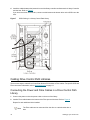
1
Scalar® 100 User’s Guide
ADVANCED DIGITAL INFORMATION CORPORATION
www.adic.com
Copyright © 2002-2006 ADIC
The information contained in this document is subject to change without notice.
This document contains proprietary information which is protected by copyright. All rights are reserved. No part of this
document may be reproduced, modified, distributed, or translated to another language without prior written consent of
ADIC.
ADIC USA
11431 Willows Road NE
Redmond, Washington
98052-4952
Tel.: 1-800-336-1233
Fax: 1-425-881-2296
This document may describe designs for which patents are pending, or have been granted. By publishing this
information, ADIC conveys no license under any patent or any other right.
ADIC shall not be liable for errors contained herein or for incidental or consequential damages (including lost profits) in
connection with the furnishing, performance or use of this material whether based on warranty, contract, or other legal
theory. ADIC makes no representation or warranty with respect to the contents of this document and specifically
disclaims any implied warranties of merchantability or fitness for any particular purpose. Further, ADIC reserves the right
to revise or change this document without obligation on the part of ADIC to notify any person or organization of such
revision or change.
Every effort has been made to acknowledge trademarks and their owners. All trademarks within this document are the
property of their respective owners. Trademarked names are used solely for identification or exemplary purposes, and
any omissions are unintentional. ADIC is a registered trademark of Advanced Digital Information Corporation.
Published: March 2006
Document Number: 6-00667-06 Rev A
Contents
1 About This Guide and Your Product
1
Product Safety Statements . . . . . . . . . . . . . . . . . . . . . . . . . . . . . . . . . . . . . . . . . . . . . . . . . . . . . . . . . . .
Product Model Number . . . . . . . . . . . . . . . . . . . . . . . . . . . . . . . . . . . . . . . . . . . . . . . . . . . . . . . . . . . . . .
Explanation of Symbols and Notes . . . . . . . . . . . . . . . . . . . . . . . . . . . . . . . . . . . . . . . . . . . . . . . . . . . . .
Other Documents you Might Need . . . . . . . . . . . . . . . . . . . . . . . . . . . . . . . . . . . . . . . . . . . . . . . . . . . . .
Getting More Information or Help . . . . . . . . . . . . . . . . . . . . . . . . . . . . . . . . . . . . . . . . . . . . . . . . . . . . . .
2 Description
1
1
1
2
2
3
Drive Support and Related Technologies . . . . . . . . . . . . . . . . . . . . . . . . . . . . . . . . . . . . . . . . . . . . . . . . 4
Front Panel Components. . . . . . . . . . . . . . . . . . . . . . . . . . . . . . . . . . . . . . . . . . . . . . . . . . . . . . . . . . . . . 4
Front Power Switch . . . . . . . . . . . . . . . . . . . . . . . . . . . . . . . . . . . . . . . . . . . . . . . . . . . . . . . . . . . . . 5
Door Lock . . . . . . . . . . . . . . . . . . . . . . . . . . . . . . . . . . . . . . . . . . . . . . . . . . . . . . . . . . . . . . . . . . . . . 5
Mailbox . . . . . . . . . . . . . . . . . . . . . . . . . . . . . . . . . . . . . . . . . . . . . . . . . . . . . . . . . . . . . . . . . . . . . . . 5
Operator Panel . . . . . . . . . . . . . . . . . . . . . . . . . . . . . . . . . . . . . . . . . . . . . . . . . . . . . . . . . . . . . . . . . 5
Back Panel Components . . . . . . . . . . . . . . . . . . . . . . . . . . . . . . . . . . . . . . . . . . . . . . . . . . . . . . . . . . . . 5
Library Controller (Library Control Path only) . . . . . . . . . . . . . . . . . . . . . . . . . . . . . . . . . . . . . . . . . . 7
Rear Power Switch . . . . . . . . . . . . . . . . . . . . . . . . . . . . . . . . . . . . . . . . . . . . . . . . . . . . . . . . . . . . . . 7
Remote Management Unit . . . . . . . . . . . . . . . . . . . . . . . . . . . . . . . . . . . . . . . . . . . . . . . . . . . . . . . . 8
Storage Networking Controllers (SNCs) . . . . . . . . . . . . . . . . . . . . . . . . . . . . . . . . . . . . . . . . . . . . . . 8
Drive Modules and Filler Plates . . . . . . . . . . . . . . . . . . . . . . . . . . . . . . . . . . . . . . . . . . . . . . . . . . . . 8
Internal Components . . . . . . . . . . . . . . . . . . . . . . . . . . . . . . . . . . . . . . . . . . . . . . . . . . . . . . . . . . . . . . . 8
Robotic System and Barcode Scanner. . . . . . . . . . . . . . . . . . . . . . . . . . . . . . . . . . . . . . . . . . . . . . . 8
Tape Magazines . . . . . . . . . . . . . . . . . . . . . . . . . . . . . . . . . . . . . . . . . . . . . . . . . . . . . . . . . . . . . . . . 9
Slot Numbering . . . . . . . . . . . . . . . . . . . . . . . . . . . . . . . . . . . . . . . . . . . . . . . . . . . . . . . . . . . . . . . . . 9
Drive Module Numbering . . . . . . . . . . . . . . . . . . . . . . . . . . . . . . . . . . . . . . . . . . . . . . . . . . . . . . . . 10
Host Attachment . . . . . . . . . . . . . . . . . . . . . . . . . . . . . . . . . . . . . . . . . . . . . . . . . . . . . . . . . . . . . . . . . . 11
Native Fibre Connections . . . . . . . . . . . . . . . . . . . . . . . . . . . . . . . . . . . . . . . . . . . . . . . . . . . . . . . . 11
SCSI Connections . . . . . . . . . . . . . . . . . . . . . . . . . . . . . . . . . . . . . . . . . . . . . . . . . . . . . . . . . . . . . . 11
3 Setting up your Scalar 100
13
Quick Start Guide . . . . . . . . . . . . . . . . . . . . . . . . . . . . . . . . . . . . . . . . . . . . . . . . . . . . . . . . . . . . . . . . .
Getting Started Road Map . . . . . . . . . . . . . . . . . . . . . . . . . . . . . . . . . . . . . . . . . . . . . . . . . . . . . . . . . .
Finding a Location . . . . . . . . . . . . . . . . . . . . . . . . . . . . . . . . . . . . . . . . . . . . . . . . . . . . . . . . . . . . . . . .
Unpacking your Library. . . . . . . . . . . . . . . . . . . . . . . . . . . . . . . . . . . . . . . . . . . . . . . . . . . . . . . . . . . . .
Cabling Library Control Path Libraries . . . . . . . . . . . . . . . . . . . . . . . . . . . . . . . . . . . . . . . . . . . . . . . . .
Cabling Drive Control Path Libraries . . . . . . . . . . . . . . . . . . . . . . . . . . . . . . . . . . . . . . . . . . . . . . . . . . .
Scalar 100User’s Guide
13
13
14
14
15
16
iii
Connecting the Power and Fibre Cables in a Drive Control Path Library . . . . . . . . . . . . . . . . . . . .
Connecting the Power and SCSI Cables in a Drive Control Path Library . . . . . . . . . . . . . . . . . . . .
Preparing the Host. . . . . . . . . . . . . . . . . . . . . . . . . . . . . . . . . . . . . . . . . . . . . . . . . . . . . . . . . . . . . . . . .
Host Coordinate System. . . . . . . . . . . . . . . . . . . . . . . . . . . . . . . . . . . . . . . . . . . . . . . . . . . . . . . . .
Installing a SCSI Adapter . . . . . . . . . . . . . . . . . . . . . . . . . . . . . . . . . . . . . . . . . . . . . . . . . . . . . . . .
Installing Drivers . . . . . . . . . . . . . . . . . . . . . . . . . . . . . . . . . . . . . . . . . . . . . . . . . . . . . . . . . . . . . . .
Installing Drivers for Microsoft Windows 2000 and Windows Server 2003 Systems . . . . . . . . .
Installing Drivers for Microsoft Windows NT 4.0 Systems. . . . . . . . . . . . . . . . . . . . . . . . . . . . . .
Verifying Communication with the Host. . . . . . . . . . . . . . . . . . . . . . . . . . . . . . . . . . . . . . . . . . . . . . . . .
4 Using the Optional Features
23
Rackmounting Your Library . . . . . . . . . . . . . . . . . . . . . . . . . . . . . . . . . . . . . . . . . . . . . . . . . . . . . . . . .
Installing Side Panels . . . . . . . . . . . . . . . . . . . . . . . . . . . . . . . . . . . . . . . . . . . . . . . . . . . . . . . . . . . . . .
Installing Casters . . . . . . . . . . . . . . . . . . . . . . . . . . . . . . . . . . . . . . . . . . . . . . . . . . . . . . . . . . . . . . . . .
Installing/Removing Drives . . . . . . . . . . . . . . . . . . . . . . . . . . . . . . . . . . . . . . . . . . . . . . . . . . . . . . . . . .
Installing a Drive . . . . . . . . . . . . . . . . . . . . . . . . . . . . . . . . . . . . . . . . . . . . . . . . . . . . . . . . . . . . . . .
Removing a Drive . . . . . . . . . . . . . . . . . . . . . . . . . . . . . . . . . . . . . . . . . . . . . . . . . . . . . . . . . . . . . .
Replacing a Drive . . . . . . . . . . . . . . . . . . . . . . . . . . . . . . . . . . . . . . . . . . . . . . . . . . . . . . . . . . . . . .
Installing a Secondary Power Supply . . . . . . . . . . . . . . . . . . . . . . . . . . . . . . . . . . . . . . . . . . . . . . . . . .
Installing Bulk Load Mailbox . . . . . . . . . . . . . . . . . . . . . . . . . . . . . . . . . . . . . . . . . . . . . . . . . . . . . . . . .
Removing the Standard Mailbox . . . . . . . . . . . . . . . . . . . . . . . . . . . . . . . . . . . . . . . . . . . . . . . . . .
Installing the Bulk Load Mailbox . . . . . . . . . . . . . . . . . . . . . . . . . . . . . . . . . . . . . . . . . . . . . . . . . . .
Installing a Storage Column . . . . . . . . . . . . . . . . . . . . . . . . . . . . . . . . . . . . . . . . . . . . . . . . . . . . . . . . .
Partitioning Your Library . . . . . . . . . . . . . . . . . . . . . . . . . . . . . . . . . . . . . . . . . . . . . . . . . . . . . . . . . . . .
Control Path. . . . . . . . . . . . . . . . . . . . . . . . . . . . . . . . . . . . . . . . . . . . . . . . . . . . . . . . . . . . . . . . . . .
Configuring AutoCleaning . . . . . . . . . . . . . . . . . . . . . . . . . . . . . . . . . . . . . . . . . . . . . . . . . . . . . . . . . . .
Working with AutoClean . . . . . . . . . . . . . . . . . . . . . . . . . . . . . . . . . . . . . . . . . . . . . . . . . . . . . . . . .
Enabling/Disabling AutoClean. . . . . . . . . . . . . . . . . . . . . . . . . . . . . . . . . . . . . . . . . . . . . . . . . . .
5 Using the Operator Panel
37
38
38
41
41
41
43
44
44
46
47
Viewing Library Information . . . . . . . . . . . . . . . . . . . . . . . . . . . . . . . . . . . . . . . . . . . . . . . . . . . . . . . . .
Getting Library Statistics. . . . . . . . . . . . . . . . . . . . . . . . . . . . . . . . . . . . . . . . . . . . . . . . . . . . . . . . .
Getting Firmware and Serial Number Information . . . . . . . . . . . . . . . . . . . . . . . . . . . . . . . . . . . . .
Getting Sensor Information. . . . . . . . . . . . . . . . . . . . . . . . . . . . . . . . . . . . . . . . . . . . . . . . . . . . . . .
Getting Slot Information . . . . . . . . . . . . . . . . . . . . . . . . . . . . . . . . . . . . . . . . . . . . . . . . . . . . . . . . .
Getting Tape Cartridge Information . . . . . . . . . . . . . . . . . . . . . . . . . . . . . . . . . . . . . . . . . . . . . . . .
iv
23
26
27
27
27
28
29
29
30
31
32
33
34
34
34
35
35
37
Understanding the Operator Panel. . . . . . . . . . . . . . . . . . . . . . . . . . . . . . . . . . . . . . . . . . . . . . . . . . . .
Getting General Library Information . . . . . . . . . . . . . . . . . . . . . . . . . . . . . . . . . . . . . . . . . . . . . . . .
Getting Drive Status Information . . . . . . . . . . . . . . . . . . . . . . . . . . . . . . . . . . . . . . . . . . . . . . . . . .
Working with Buttons . . . . . . . . . . . . . . . . . . . . . . . . . . . . . . . . . . . . . . . . . . . . . . . . . . . . . . . . . . .
Getting Library Messages. . . . . . . . . . . . . . . . . . . . . . . . . . . . . . . . . . . . . . . . . . . . . . . . . . . . . . . .
Getting Mailbox Status . . . . . . . . . . . . . . . . . . . . . . . . . . . . . . . . . . . . . . . . . . . . . . . . . . . . . . . . . .
Menu Guidelines. . . . . . . . . . . . . . . . . . . . . . . . . . . . . . . . . . . . . . . . . . . . . . . . . . . . . . . . . . . . . . . . . .
Using the Main Menu . . . . . . . . . . . . . . . . . . . . . . . . . . . . . . . . . . . . . . . . . . . . . . . . . . . . . . . . . . . . . .
The Menu Tree . . . . . . . . . . . . . . . . . . . . . . . . . . . . . . . . . . . . . . . . . . . . . . . . . . . . . . . . . . . . . . . . . . .
Using Commands that Require an Offline State. . . . . . . . . . . . . . . . . . . . . . . . . . . . . . . . . . . . . . . . . .
6 Getting Information
16
17
18
19
19
19
19
21
22
47
47
48
49
50
52
Contents
Viewing Drive Information. . . . . . . . . . . . . . . . . . . . . . . . . . . . . . . . . . . . . . . . . . . . . . . . . . . . . . . . . . .
Getting Logs . . . . . . . . . . . . . . . . . . . . . . . . . . . . . . . . . . . . . . . . . . . . . . . . . . . . . . . . . . . . . . . . . . . . .
Printing Logs (HyperTerminal) . . . . . . . . . . . . . . . . . . . . . . . . . . . . . . . . . . . . . . . . . . . . . . . . . . . .
Getting the Command Logs . . . . . . . . . . . . . . . . . . . . . . . . . . . . . . . . . . . . . . . . . . . . . . . . . . . . . .
Getting Error Logs . . . . . . . . . . . . . . . . . . . . . . . . . . . . . . . . . . . . . . . . . . . . . . . . . . . . . . . . . . . . .
Getting Drive Logs . . . . . . . . . . . . . . . . . . . . . . . . . . . . . . . . . . . . . . . . . . . . . . . . . . . . . . . . . . . . .
Clear Log. . . . . . . . . . . . . . . . . . . . . . . . . . . . . . . . . . . . . . . . . . . . . . . . . . . . . . . . . . . . . . . . . . .
Force Dump . . . . . . . . . . . . . . . . . . . . . . . . . . . . . . . . . . . . . . . . . . . . . . . . . . . . . . . . . . . . . . . .
Copy Dump . . . . . . . . . . . . . . . . . . . . . . . . . . . . . . . . . . . . . . . . . . . . . . . . . . . . . . . . . . . . . . . . .
Preserve Dump Dialog . . . . . . . . . . . . . . . . . . . . . . . . . . . . . . . . . . . . . . . . . . . . . . . . . . . . . . . .
7 Running your Library
59
Turning on the Library . . . . . . . . . . . . . . . . . . . . . . . . . . . . . . . . . . . . . . . . . . . . . . . . . . . . . . . . . . . . .
Turning off the Library . . . . . . . . . . . . . . . . . . . . . . . . . . . . . . . . . . . . . . . . . . . . . . . . . . . . . . . . . . . . .
Moving Tape Cartridges . . . . . . . . . . . . . . . . . . . . . . . . . . . . . . . . . . . . . . . . . . . . . . . . . . . . . . . . . . . .
Moving the Picker . . . . . . . . . . . . . . . . . . . . . . . . . . . . . . . . . . . . . . . . . . . . . . . . . . . . . . . . . . . . . . . . .
Taking Inventory . . . . . . . . . . . . . . . . . . . . . . . . . . . . . . . . . . . . . . . . . . . . . . . . . . . . . . . . . . . . . . . . . .
Adding/Removing Tape Cartridges . . . . . . . . . . . . . . . . . . . . . . . . . . . . . . . . . . . . . . . . . . . . . . . . . . .
Importing Tape Cartridges . . . . . . . . . . . . . . . . . . . . . . . . . . . . . . . . . . . . . . . . . . . . . . . . . . . . . . .
Manually Inserting Tape Cartridges . . . . . . . . . . . . . . . . . . . . . . . . . . . . . . . . . . . . . . . . . . . . . . . .
Exporting a Tape Cartridge . . . . . . . . . . . . . . . . . . . . . . . . . . . . . . . . . . . . . . . . . . . . . . . . . . . . . .
Manually Removing Tape Cartridges . . . . . . . . . . . . . . . . . . . . . . . . . . . . . . . . . . . . . . . . . . . . . . .
Working with Cleaning Cartridges . . . . . . . . . . . . . . . . . . . . . . . . . . . . . . . . . . . . . . . . . . . . . . . . . . . .
Viewing Cleaning Cartridge Status . . . . . . . . . . . . . . . . . . . . . . . . . . . . . . . . . . . . . . . . . . . . . . . . .
Importing Cleaning Cartridges . . . . . . . . . . . . . . . . . . . . . . . . . . . . . . . . . . . . . . . . . . . . . . . . . . . .
Exporting Cleaning Cartridges . . . . . . . . . . . . . . . . . . . . . . . . . . . . . . . . . . . . . . . . . . . . . . . . . . . .
Working with Drives . . . . . . . . . . . . . . . . . . . . . . . . . . . . . . . . . . . . . . . . . . . . . . . . . . . . . . . . . . . . . . .
Unloading a Drive . . . . . . . . . . . . . . . . . . . . . . . . . . . . . . . . . . . . . . . . . . . . . . . . . . . . . . . . . . . . . .
8 Configuring your Library
67
67
67
69
70
70
71
72
72
73
73
75
Displaying SACs (Advanced vs Normal Service) . . . . . . . . . . . . . . . . . . . . . . . . . . . . . . . . . . . . . . . . .
Updating Firmware . . . . . . . . . . . . . . . . . . . . . . . . . . . . . . . . . . . . . . . . . . . . . . . . . . . . . . . . . . . . . . . .
Preferred Methods . . . . . . . . . . . . . . . . . . . . . . . . . . . . . . . . . . . . . . . . . . . . . . . . . . . . . . . . . . . . .
Updating Library Firmware . . . . . . . . . . . . . . . . . . . . . . . . . . . . . . . . . . . . . . . . . . . . . . . . . . . . . . .
Updating Drive Firmware . . . . . . . . . . . . . . . . . . . . . . . . . . . . . . . . . . . . . . . . . . . . . . . . . . . . . . . .
Scalar 100 User’s Guide
59
59
60
61
61
62
63
63
63
64
64
64
65
65
65
66
67
Using AIT WORM Technology . . . . . . . . . . . . . . . . . . . . . . . . . . . . . . . . . . . . . . . . . . . . . . . . . . . . . . .
Configuring General Characteristics . . . . . . . . . . . . . . . . . . . . . . . . . . . . . . . . . . . . . . . . . . . . . . . . . . .
Configuring Library Characteristics . . . . . . . . . . . . . . . . . . . . . . . . . . . . . . . . . . . . . . . . . . . . . . . .
Configuring Additional Library Options . . . . . . . . . . . . . . . . . . . . . . . . . . . . . . . . . . . . . . . . . . . . . .
Reading Barcodes of Media in Tape Drives . . . . . . . . . . . . . . . . . . . . . . . . . . . . . . . . . . . . . . . . . . . . .
Configuring Barcode Length . . . . . . . . . . . . . . . . . . . . . . . . . . . . . . . . . . . . . . . . . . . . . . . . . . . . . . . . .
Setting Drive SCSI IDs . . . . . . . . . . . . . . . . . . . . . . . . . . . . . . . . . . . . . . . . . . . . . . . . . . . . . . . . . . . . .
Setting Drive Loop IDs. . . . . . . . . . . . . . . . . . . . . . . . . . . . . . . . . . . . . . . . . . . . . . . . . . . . . . . . . . . . . .
Setting the Date and Time . . . . . . . . . . . . . . . . . . . . . . . . . . . . . . . . . . . . . . . . . . . . . . . . . . . . . . . . . .
Password Protecting the Operator Panel . . . . . . . . . . . . . . . . . . . . . . . . . . . . . . . . . . . . . . . . . . . . . . .
Locking/Unlocking the Mailbox . . . . . . . . . . . . . . . . . . . . . . . . . . . . . . . . . . . . . . . . . . . . . . . . . . . . . . .
9 Maintaining your Library
52
53
53
54
54
54
55
55
56
56
75
75
75
75
76
v
Creating or Erasing a FUP Tape . . . . . . . . . . . . . . . . . . . . . . . . . . . . . . . . . . . . . . . . . . . . . . . . .
Exercising the Picker Fingers . . . . . . . . . . . . . . . . . . . . . . . . . . . . . . . . . . . . . . . . . . . . . . . . . . . . . . . .
Getting and Putting Tape Cartridges . . . . . . . . . . . . . . . . . . . . . . . . . . . . . . . . . . . . . . . . . . . . . . .
Opening/Closing and Extending/Retracting . . . . . . . . . . . . . . . . . . . . . . . . . . . . . . . . . . . . . . . . . .
Exercising the Barcode Scanner . . . . . . . . . . . . . . . . . . . . . . . . . . . . . . . . . . . . . . . . . . . . . . . . . . . . .
Exercising the Picker Axes . . . . . . . . . . . . . . . . . . . . . . . . . . . . . . . . . . . . . . . . . . . . . . . . . . . . . . . . . .
Moving the Picker in a Motion Pattern . . . . . . . . . . . . . . . . . . . . . . . . . . . . . . . . . . . . . . . . . . . . . .
Moving the Picker in Increments . . . . . . . . . . . . . . . . . . . . . . . . . . . . . . . . . . . . . . . . . . . . . . . . . .
Sending the Picker to the Home Position . . . . . . . . . . . . . . . . . . . . . . . . . . . . . . . . . . . . . . . . . . . .
Exercising the Library . . . . . . . . . . . . . . . . . . . . . . . . . . . . . . . . . . . . . . . . . . . . . . . . . . . . . . . . . . . . . .
Running a Demo. . . . . . . . . . . . . . . . . . . . . . . . . . . . . . . . . . . . . . . . . . . . . . . . . . . . . . . . . . . . . . .
Running a Self Test . . . . . . . . . . . . . . . . . . . . . . . . . . . . . . . . . . . . . . . . . . . . . . . . . . . . . . . . . . . .
Teaching the Library . . . . . . . . . . . . . . . . . . . . . . . . . . . . . . . . . . . . . . . . . . . . . . . . . . . . . . . . . . . .
Resetting a Drive . . . . . . . . . . . . . . . . . . . . . . . . . . . . . . . . . . . . . . . . . . . . . . . . . . . . . . . . . . . . . . . . .
Servicing Drives . . . . . . . . . . . . . . . . . . . . . . . . . . . . . . . . . . . . . . . . . . . . . . . . . . . . . . . . . . . . . . . . . .
Preparing a Drive . . . . . . . . . . . . . . . . . . . . . . . . . . . . . . . . . . . . . . . . . . . . . . . . . . . . . . . . . . . . . .
Running Drive Diagnostic Tests . . . . . . . . . . . . . . . . . . . . . . . . . . . . . . . . . . . . . . . . . . . . . . . . . . .
10 Working with Tapes and Barcodes
85
Selecting Approved Media Types. . . . . . . . . . . . . . . . . . . . . . . . . . . . . . . . . . . . . . . . . . . . . . . . . . . . .
Write-Protecting Tape Cartridges . . . . . . . . . . . . . . . . . . . . . . . . . . . . . . . . . . . . . . . . . . . . . . . . . . . . .
Tape Use Guidelines . . . . . . . . . . . . . . . . . . . . . . . . . . . . . . . . . . . . . . . . . . . . . . . . . . . . . . . . . . . . . .
Using Barcode Labels . . . . . . . . . . . . . . . . . . . . . . . . . . . . . . . . . . . . . . . . . . . . . . . . . . . . . . . . . . . . .
Applying Barcode Labels . . . . . . . . . . . . . . . . . . . . . . . . . . . . . . . . . . . . . . . . . . . . . . . . . . . . . . . .
Barcode Label Requirements . . . . . . . . . . . . . . . . . . . . . . . . . . . . . . . . . . . . . . . . . . . . . . . . . . . . .
11 Using the Remote Management Unit
vi
85
85
85
86
86
86
89
Supported Browsers . . . . . . . . . . . . . . . . . . . . . . . . . . . . . . . . . . . . . . . . . . . . . . . . . . . . . . . . . . . . . . .
RMU Requirements . . . . . . . . . . . . . . . . . . . . . . . . . . . . . . . . . . . . . . . . . . . . . . . . . . . . . . . . . . . . . . .
Setting up the RMU . . . . . . . . . . . . . . . . . . . . . . . . . . . . . . . . . . . . . . . . . . . . . . . . . . . . . . . . . . . . . . .
Starting the RMU . . . . . . . . . . . . . . . . . . . . . . . . . . . . . . . . . . . . . . . . . . . . . . . . . . . . . . . . . . . . . . . . .
Logging into the RMU. . . . . . . . . . . . . . . . . . . . . . . . . . . . . . . . . . . . . . . . . . . . . . . . . . . . . . . . . . . . . .
Checking Status and General Information . . . . . . . . . . . . . . . . . . . . . . . . . . . . . . . . . . . . . . . . . . . . . .
Configuring Network Parameters . . . . . . . . . . . . . . . . . . . . . . . . . . . . . . . . . . . . . . . . . . . . . . . . . . . . .
Configuring SNMP . . . . . . . . . . . . . . . . . . . . . . . . . . . . . . . . . . . . . . . . . . . . . . . . . . . . . . . . . . . . . . . .
Downloading the SNMP MIB File . . . . . . . . . . . . . . . . . . . . . . . . . . . . . . . . . . . . . . . . . . . . . . . . . .
Configuring RMU User Accounts . . . . . . . . . . . . . . . . . . . . . . . . . . . . . . . . . . . . . . . . . . . . . . . . . . . . .
Adding/Removing Users . . . . . . . . . . . . . . . . . . . . . . . . . . . . . . . . . . . . . . . . . . . . . . . . . . . . . . . . .
Changing a Password . . . . . . . . . . . . . . . . . . . . . . . . . . . . . . . . . . . . . . . . . . . . . . . . . . . . . . . . . .
Configuring the Time and Date. . . . . . . . . . . . . . . . . . . . . . . . . . . . . . . . . . . . . . . . . . . . . . . . . . . . . . .
Updating Firmware . . . . . . . . . . . . . . . . . . . . . . . . . . . . . . . . . . . . . . . . . . . . . . . . . . . . . . . . . . . . . . . .
Viewing Diagnostic Files. . . . . . . . . . . . . . . . . . . . . . . . . . . . . . . . . . . . . . . . . . . . . . . . . . . . . . . . . . . .
Using the Operator Panel (via the RMU) . . . . . . . . . . . . . . . . . . . . . . . . . . . . . . . . . . . . . . . . . . . . . . .
Viewing Logs . . . . . . . . . . . . . . . . . . . . . . . . . . . . . . . . . . . . . . . . . . . . . . . . . . . . . . . . . . . . . . . . . . . .
Getting Help . . . . . . . . . . . . . . . . . . . . . . . . . . . . . . . . . . . . . . . . . . . . . . . . . . . . . . . . . . . . . . . . . . . . .
Replacing the RMU . . . . . . . . . . . . . . . . . . . . . . . . . . . . . . . . . . . . . . . . . . . . . . . . . . . . . . . . . . . . . . . .
12 Troubleshooting and Help
76
77
77
78
79
79
79
80
80
80
80
81
81
82
82
82
83
90
90
90
91
91
91
92
92
92
92
93
93
93
94
94
95
95
95
95
97
Contents
Service Action Codes . . . . . . . . . . . . . . . . . . . . . . . . . . . . . . . . . . . . . . . . . . . . . . . . . . . . . . . . . . . . . . 97
Operator Intervention Messages . . . . . . . . . . . . . . . . . . . . . . . . . . . . . . . . . . . . . . . . . . . . . . . . . . . . 105
Operator Information Messages . . . . . . . . . . . . . . . . . . . . . . . . . . . . . . . . . . . . . . . . . . . . . . . . . . . . . 109
Interpreting Drive LEDs . . . . . . . . . . . . . . . . . . . . . . . . . . . . . . . . . . . . . . . . . . . . . . . . . . . . . . . . . . . 110
13 Specifications
111
Power . . . . . . . . . . . . . . . . . . . . . . . . . . . . . . . . . . . . . . . . . . . . . . . . . . . . . . . . . . . . . . . . . . . . . . . . .
Tape Cartridge Capacity . . . . . . . . . . . . . . . . . . . . . . . . . . . . . . . . . . . . . . . . . . . . . . . . . . . . . . . . . . .
Drive Capacity . . . . . . . . . . . . . . . . . . . . . . . . . . . . . . . . . . . . . . . . . . . . . . . . . . . . . . . . . . . . . . . . . .
Allowed Tape Cartridges and Storage Capacity. . . . . . . . . . . . . . . . . . . . . . . . . . . . . . . . . . . . . . . . .
AIT . . . . . . . . . . . . . . . . . . . . . . . . . . . . . . . . . . . . . . . . . . . . . . . . . . . . . . . . . . . . . . . . . . . . . . . . .
SDLT/DLT . . . . . . . . . . . . . . . . . . . . . . . . . . . . . . . . . . . . . . . . . . . . . . . . . . . . . . . . . . . . . . . . . . .
LTO. . . . . . . . . . . . . . . . . . . . . . . . . . . . . . . . . . . . . . . . . . . . . . . . . . . . . . . . . . . . . . . . . . . . . . . .
Scalar 100 User’s Guide
111
112
112
112
113
114
115
vii
viii
Contents
About This Guide and Your Product
This guide contains information and instructions necessary for the normal operation and management of
the Scalar® 100. This guide is intended for anyone interested in learning about or anyone that needs to know
how to install, configure, and operate the Scalar 100.
Note
Be sure to read all operating instructions in this manual and in the System, Safety, and
Regulatory Information Guide before operating this product.
This guide contains information and instructions necessary for the normal operation and management of
the Scalar 100 library. This guide is intended for system administrators, operators, or anyone interested in
learning about or using the Scalar 100.
Product Safety Statements
This product is designed for processing magnetic tape cartridges. Any other application is not considered
the intended use. ADIC will not be held liable for damage arising from unauthorized use of the product. The
user assumes all risk in this aspect.
This unit is engineered and manufactured to meet all safety and regulatory requirements. Be aware that
improper use may result in bodily injury, damage to the equipment, or interference with other equipment.
WARNING
BEFORE POWERING ON OR USING THIS EQUIPMENT, READ THE SYSTEM,
SAFETY, AND REGULATORY INFORMATION GUIDE. KEEP THE GUIDE FOR
FUTURE REFERENCE.
Product Model Number
The Scalar 100 model number is as follows: SC100
Explanation of Symbols and Notes
The following symbols appear throughout this document to highlight important information.
Scalar 100 User’s Guide
1
WARNING
INDICATES A POTENTIALLY HAZARDOUS SITUATION WHICH, IF NOT
AVOIDED, COULD RESULT IN DEATH OR BODILY INJURY.
CAUTION
Indicates a situation that may cause possible damage to equipment, loss of
data, or interference with other equipment.
Note
Indicates important information that helps you make better use of your system.
Other Documents you Might Need
The following documents are also available for this product. These documents can be found on the product
CD or at www.adic.com/manuals:
•
AMC Online Help
•
AMC User’s Guide (6-00064-xx)
•
SNC 5101 User’s Guide (62-0197-xx)
•
SNC 6101 Installation and Maintenance Guide (6-00701-xx)
•
SNC 450x User’s Guide (6-00998-xx)
•
SNC Firmware 4 Reference Manual (6-00706-xx)
•
System, Safety, and Regulatory Information Guide (6-00618-xx)
Note
Release Notes are also available for this product. The Release Notes describe changes
to your system or firmware since the last release, provide compatibility information, and
discuss any known issues and workarounds. The Release Notes can be found in the
product box or at www.adic.com/manuals.
Getting More Information or Help
More information about this product is available on the Customer Service Center website at
www.adic.com/csc. The Customer Service Center contains a collection of information, including answers to
frequently asked questions (FAQs). You can also access software, firmware, and drivers through this site.
For further assistance, or if training is desired, contact ADIC:
2
In the USA:
800-827-3822
In Europe and Japan:
00-800-9999-3822
For additional contact information:
www.adic.com/contact
To open a Service Request:
www.adic.com/techsup
About This Guide and Your Product
Description
The Scalar 100 automates the retrieval, storage, and control of tape cartridges. It is designed for use in a
standard office environment, with a fully finished appearance, or as a rackmounted unit.
The library supports many different drive types and, depending on the type of drive, can contain up to eight
drives. There is a mailbox on the front door for inserting and removing tapes. In addition, the operator panel
on the front of the library allows you to fully control and configure your library.
There are two types of Scalar 100 libraries available: Library Control Path and Drive Control Path. Library
Control Path libraries connect the host to the library through a SCSI connection. Drive Control Path libraries
connect the host directly to the drive. Refer to Host Attachment on page 11 for more information on Library
Control Path and Drive Control Path libraries.
For specific information about your library, including data capacity and tape cartridge capacity, refer to
Specifications on page 111.
Figure 1
Scalar 100
Scalar 100 User’s Guide
3
Drive Support and Related Technologies
Drive Control Path libraries support the following tape drives:
•
AIT type drives (AIT-2 HVD & LVD, AIT-3 LVD)
•
DLT type drives (7000 HVD, 8000 HVD & LVD, SDLT-220 HVD & LVD, SDLT-320 LVD, SDLT-600
LVD)
•
LTO type drives (LTO-1 HVD & LVD, LTO-2 LVD, LTO-3 LVD & Fibre)
Note
Library Control Path libraries do not support mixing different drives types. This
includes different models of the same drive type. Drive Control Path libraries do
not support mixing different drive types within the same partition; however,
different generations of LTO drives can exist within the same partition. Refer to
Partitioning Your Library on page 34 for more information.
The drive type affects the tape cartridge and overall storage capacity. For specific information about your
library storage capacity and allowed tape cartridges, refer to Specifications on page 111.
With the correct drive and library firmware running, an AIT-3 library supports the Sony® AIT™ WORM
(write-once-read-many) technology, which allows for non-rewritable and non-erasable data to be written.
This technology provides extra security for your data by preventing accidental erasure.
Front Panel Components
The following graphic shows the front panel components. The following text describes the components in
detail.
Figure 2
4
Front Panel Components
Description
Front Power Switch
There are two power switches on the library: the front power switch and the rear power switch.
Turning off the front power switch removes power from the internal electronics and removes power from the
drives, but the library still contains standby power. The standby power can only be turned off by the rear
power switch. Refer to Rear Power Switch on page 7.
WARNING
TO COMPLETELY REMOVE ALL POWER, EITHER USE THE REAR
POWER SWITCH OR DISCONNECT THE POWER CORD FROM THE
ELECTRICAL SOURCE.
Door Lock
The Scalar 100 door lock protects your data from the risk of tampering and prevents unauthorized personnel
from entering the mechanical area of the Scalar 100 where serious injury could occur.
When locked, the library door can only be opened from the outside with a key. Authorized personnel are
responsible for the security of the key. When shipped, the front door is locked. The key is attached to the
back panel of the library.
WARNING
THE MECHANICAL COMPONENTS OF THE LIBRARY CAN CAUSE
SERIOUS INJURY. ACCESS TO THE LIBRARY SHOULD BE
RESTRICTED TO AUTHORIZED PERSONNEL ONLY.
Mailbox
The mailbox allows you to import and export tape cartridges without interrupting the normal operation of the
library; however, it can also be configured as additional storage slots.
There are two models of the mailbox:
•
The standard mailbox has a capacity of one or two tape cartridges. (One tape cartridge for DLT/
SDLT and LTO libraries and two tape cartridges for AIT libraries.)
•
The optional bulk load mailbox enables you to load multiple tape cartridges at one time.
•
AIT bulk load mailboxes holds 16 tape cartridges in two magazines.
•
LTO bulk load mailboxes holds 12 tape cartridges in two magazines.
•
DLT/SDLT bulk load mailbox holds 10 tape cartridges in two magazines.
Operator Panel
The operator panel is an LCD screen that enables you to monitor, configure, and service your library. For
detailed information on the operator panel, refer to Using the Operator Panel on page 37.
Back Panel Components
The following graphics show the back panel components of Library Control Path and Drive Control Path
libraries. Where appropriate, following the graphics, the components are described in detail.
Scalar 100 User’s Guide
5
Figure 3
6
Back Panel Components of Library Control Path Libraries
Description
Figure 4
Back Panel Components of Drive Control Path Libraries
Library Controller (Library Control Path only)
The library controller is part of Library Control Path libraries. The library controller controls all operations in
the library, including the interaction between the library and operators. The library firmware on the library
controller creates and maintains the library configuration, the physical location of the robotic system, and
the inventory of cartridges. The resulting database is maintained in library controller memory.
The SCSI connections are located on the library controller. A switch on the library controller allows you to
switch your library between LVD and HVD connections.
Rear Power Switch
Turning off the rear power switch removes all power from the library. Turn off the rear power switch
whenever you are servicing your library. In the event of danger to personnel or property, immediately turn
off the rear power switch.
However, except in emergencies, use the normal shutdown procedure before switching off the rear power
switch. ADIC is not responsible for damage caused by improper use of the rear power switch. This risk lies
entirely with the user.
Scalar 100 User’s Guide
7
Remote Management Unit
The Remote Management Unit (RMU) allows remote access to the library via a web browser. The RMU
resides in each system and is pre-installed at the factory.
The RMU performs the following functions:
•
Provides remote operation of all library operator panel functions via a Web browser.
•
Allows the user to check the status of the system, firmware levels, and other useful information.
•
Updates RMU, drive (LTO only), and library controller firmware.
•
Supports Simple Network Management Protocol (SNMP) version 1.0 and acts as an SNMP-server,
generating SNMP traps and responding to SNMP requests.
•
Supports ADIC Library Management Information Base (MIB) version 2.0.
•
Detects a power loss and generates an SNMP trap for notification.
•
Enables the retrieval of library logs and library, drive, and RMU diagnostic files.
•
Allows RMU configuration changes such as network, users, and date/time changes.
For information on using the RMU, refer to Using the Remote Management Unit on page 89.
Storage Networking Controllers (SNCs)
The Scalar 100 offers optional Storage Networking Controllers (SNC) that provide many features for Scalar
100 libraries. For example, they increase data transfer rates, enable you to use and manage your library in
a Storage Area Network (SAN) and provide Fibre to SCSI or Gigabit Ethernet to SCSI connectivity.
The available feature set depends on which SNC you integrate into your library. The Scalar 100 supports
the SNC 5101, SNC 6101, and the SNC 4500. To learn more about the available SNCs, visit www.adic.com
or reference the applicable manual(s) on the Scalar 100 product CD.
Drive Modules and Filler Plates
A drive module is the component that holds the drive and the Fibre or SCSI connections between the drive
and the library. Filler plates cover empty drive slots to prevent debris from entering the library.
If you do not have a drive filler plate, contact ATAC before removing a drive.
Internal Components
The robotic system and magazines are the key internal components of the Scalar 100.
Robotic System and Barcode Scanner
The robotic system identifies and moves cartridges between the storage slots, tape drives, and the mailbox.
The robotic arm (picker) has picker fingers that enable it to grab media cartridges and move them into
position along X, Y, and Z motion coordinates.
Each tape cartridge contains a barcode that is read by the barcode scanner during the inventory process.
The barcode scanner is also used during the teaching process where it reads the fiducial labels to identify
the types of storage and tape drives installed in the library.
8
Description
Every tape cartridge must have a machine and unique operator-readable barcode label attached to it. Tape
cartridges cannot have duplicate barcode labels. This barcode identifies the volume serial number (volser).
The library stores the physical location of the tape cartridge in an inventory database based on the volser.
All library or host requests reference the location of tape cartridges based off of this barcode number.
Tape Magazines
Tape cartridges are stored in removable magazines in the library. You cannot insert cartridges improperly.
The magazines only accept tape cartridges placed in the correct orientation. Once inserted, the tape
cartridges will be retained in the magazine even when the magazine is inverted and shaken lightly.
Each magazine has a fiducial barcode label at the bottom of the magazine. This label is read by the barcode
scanner during a teach process.
Slot Numbering
Every slot in the library has a distinct number that identifies it. The format is: column/magazine/slot.
The values are assigned as follows:
•
The columns are numbered 1 to 5 clockwise from the mailbox column.
•
The magazines within each column are designated A to C from top to bottom.
•
The slots are numbered as follows:
•
The slots within each magazine are numbered 1 to N from top to bottom (where N is the number
of tape cartridges allowed for that media type).
•
The fixed slots in columns 2, 4, and 5 that do not have a magazine designation are always
numbered 0. For example, the coordinate for the fixed slot in column 2 would be “2 - 0”.
Note
For reference, the location for the picker is identified as [0 @ 0] on the operator
panel.
Scalar 100 User’s Guide
9
Figure 5
Storage Slot Numbering
Drive Module Numbering
The drive modules are numbered 1 to N from bottom to top, where N is the number of drives allowed for that
media type.
10
Description
Host Attachment
The Scalar 100 is a SCSI target device supporting communication with a host through fibre or SCSI
connections.
Native Fibre Connections
A library supporting native fibre attachments communicates with a host through an intermediary LUN-1
(Logical Unit Number) interface in one or more installed drives. In this type of connection, a host is
connected directly to a drive rather than a library. Communication is accomplished as a host sends
commands to and receives status or responses from one or more LUN-1 enabled drives.
LTO-3 drive modules support native fibre connections. Each drive has a single LC fibre connector located
in back of the module for attachments.
SCSI Connections
A library supporting SCSI connections can be connected to LTO-1 or LTO-2 drive modules via a SCSI-2
Low Voltage Differential or High Voltage Differential (LTO-1 only) SCSI bus. Both ends of the bus must be
terminated. A terminator is shipped with each library. The SCSI LTO-3 drive module is LVD only. The design
of the library allows the SCSI type (LVD or HVD) to be configured at the customer site with a switch located
on the Library Controller.
Each LTO drive module has two HD-68 connectors for attachments. (When attaching to a 1-byte host, a 1byte to 2-byte interposer is required.) Although the library can be attached to a wide SCSI bus, it is not a
wide SCSI device and its SCSI ID must be in the range of 0 to 7. The default SCSI ID for the library is 0.
Libraries that do not have native fibre connection capabilities can be connected to a Storage Area Network
(SAN) via an optional Storage Networking Controller (SNC), where the SNC converts either Fibre Channel
protocol or Gigabit Ethernet (GbE) protocol to parallel SCSI protocol.
Scalar 100 User’s Guide
11
12
Description
Setting up your Scalar 100
Setting up your library includes actions such as unpacking, connecting power cords and SCSI or Fibre
cables, setting SCSI IDs or Loop IDs, and preparing the host computer. The actions discussed here are
those you would need the first time you set up your library and if your library is ever moved or reconfigured.
Information on turning on and off the library, is located in Running your Library on page 59, as it is part of
everyday tasks.
Quick Start Guide
For simple setup instructions, refer to the Quick Start Guide available on the Scalar 100 Documentation and
Software CD or as a printed document in your product box. For more detailed instructions, refer to the
Getting Started Road Map on page 13.
To view the Quick Start Guide, you need to have Adobe® Acrobat® Reader® installed. Go to
www.adobe.com/acrobat/ to download a free copy.
Getting Started Road Map
To set up your Scalar 100 for the first time, complete all the basic steps listed here.
1
Find a location for your library.
Refer to Finding a Location on page 14.
2
Unpack your library.
Refer to Unpacking your Library on page 14.
3
Install any optional or additional hardware that you ordered for your library.
Refer to Using the Optional Features on page 23.
4
Connect the power cords and SCSI or Fibre cables.
Refer to Cabling Library Control Path Libraries on page 15 or Cabling Drive Control Path Libraries on
page 16.
5
Turn on the library.
Refer to Turning on the Library on page 59.
6
If necessary, set the SCSI IDs or Loop IDs for the library and drives so that they are unique from any
other device on the SCSI bus or Fibre attachments.
Scalar 100 User’s Guide
13
Refer to Configuring your Library on page 67.
7
Prepare the host system.
Refer to Cabling Drive Control Path Libraries on page 16.
8
Verify communication between the library and the host.
Refer to Verifying Communication with the Host on page 22.
Finding a Location
When positioning the library, consider the following:
•
The location must provide adequate front and rear ventilation (at least two inches, the space
provided by the cabling will suffice).
•
Situate the product away from heat sources such as radiators, heat registers, furnaces, or other
heat-producing appliances.
•
Ensure a power source (only of the type directed in the operating instructions or as marked on the
product label) is available.
•
Route the AC line cord so that it is not likely to be walked on or pinched by items placed upon or
against it, paying particular attention to the cord at the wall receptacle, and the point where the cord
exits from the product.
•
Ensure that objects will not fall and liquids are not spilled into the product’s enclosure through
openings.
•
Do not position in an area that will expose the unit to moisture or high temperatures or extreme low
temperatures.
•
Keep the unit away from direct strong magnetic fields, excessive dust, and electronic/electrical
equipment that generate electrical noise.
•
Position the unit on a firm, level surface free from vibration.
Unpacking your Library
1
CAUTION
If you need to return your library, you must ship it in the original or
equivalent packing materials or your warranty may be invalidated.
CAUTION
Do not move the picker assembly along the rotary axis by hand as it
will be damaged. The picker assembly can be rotated by turning the
gear on the rotary motor by hand.
Unpack all items from the carton.
Save the packing materials in case you need to move or ship the system in the future.
2
Inspect the items that came with your library and ensure none are damaged.
3
Complete either the written registration card or register the product on the ADIC website at
www.adic.com.
The Scalar 100 serial number is located on the product label on the back of the library and on the inside
of the front door.
14
Setting up your Scalar 100
4
Remove the key from the rear panel of the library. Unlock and open the front door.
5
Remove the interior packaging or securing material from the library to allow picker movement. (Make
sure to remove the rubber band from around the picker.)
6
Install tape cartridges into magazines.
Cabling Library Control Path Libraries
Part of the setup process for Library Control Path libraries is connecting the power and SCSI cables. When
setting up your library, ensure that the last device on the SCSI bus is properly terminated. An appropriate
terminator is shipped with each library. For specific SCSI connection information, refer to Host Attachment
on page 11.
The default SCSI ID is 0 for the library controller, this default value will appear
when a new main controller PCBA is installed or after a firmware update.
Note
1
Connect the power cord to the power outlet on the rear of the library.
2
On the bottom most drive, connect a jumper cable to the top SCSI connector and then to the bottom
SCSI connector on the drive above it. Repeat this for all drives in the SCSI bus.
If you have more than two drives, split the drives between SCSI buses so that there are no more than
two drives per SCSI bus. Refer to the following steps.
Note
3
AIT libraries cannot have tape drives installed in the bottom-most or topmost drive module slots.
Terminate the last device(s) on the SCSI bus(es) with an appropriate terminator (LVD or HVD). Refer
to Figure 6.
Figure 6
SCSI Bus Terminator
Scalar 100 User’s Guide
15
4
Install the cables between the bottom drive and the library controller and between the Library Controller
and the host. Refer to Figure 7.
If you have more than one SCSI bus, connect a cable between the bottom drive on the SCSI bus to the
host.
Figure 7
SCSI Cabling in a Library Control Path Library
Cabling Drive Control Path Libraries
There are two ways to cable Drive Control Path libaries: SCSI cables or Fibre cables. For specific SCSI and
Fibre connection information, refer to Host Attachment on page 11.
Connecting the Power and Fibre Cables in a Drive Control Path
Library
1
Connect the power cord to the power outlet on the rear of the library.
2
Install a Fibre cable between the bottom drive Fibre port and the host. Refer to Figure 8.
Repeat for each additional drive installed.
Note
16
The Fibre cable can be connected from the drive to a switch rather than a
host.
Setting up your Scalar 100
Figure 8
Fibre Channel Cabling in a Drive Control Path Library
Connecting the Power and SCSI Cables in a Drive Control Path
Library
1
Connect the power cord to the power outlet on the rear of the library.
2
On the bottom-most drive, connect a jumper cable to the top SCSI connector on the drive above it.
Repeat this for all of the drives.
If you have more than two drive, split the drive between SCSI buses.
3
Terminate the SCSI buses with an appropriate termintator (LVD or HVD).
4
If you have more than one SCSI bus, connect a SCSI cable between the bottom drive and the host.
Refer to Figure 9 on page 18.
Scalar 100 User’s Guide
17
Figure 9
SCSI Cabling in a Drive Control Path Library
Preparing the Host
If necessary, install a SCSI host system adapter, software, and compatible driver(s). Refer to the manuals
for the host system and SCSI host system adapter for detailed instructions. In addition, follow these general
guidelines:
18
•
When the host server system is turned on, install the software, and/or driver(s) that are compatible
with the library.
•
If the host server system is connected to a network, check with the system administrator before
turning off the power to the host.
•
Prevent electrostatic discharge (ESD) by following proper procedures. Always use wrist-grounding
straps and anti-static mats when handling internal components.
•
Make certain the host server system has an open expansion slot.
Setting up your Scalar 100
Host Coordinate System
To manipulate the media within the library, the host must reference each movement with source and target
designations. This is done via element addressing, which specifies precisely which slots within the library
are to be used. The following addressing scheme is used for the library. These values may need to be
entered into your host application.
Table 1
Element Addressing
Slot Type
Starting Address
Storage
4096 : (0x1000)
Mailbox
16 : (0x0010)
Drives
256: (0x0100)
Picker
1: (0x0001)
Installing a SCSI Adapter
For SCSI libraries to communicate, your host computer must have a SCSI adapter. If your host computer
does not have SCSI capability, you will need to install a SCSI adapter. For installation instructions, refer to
the manual that comes with the adapter.
Installing Drivers
When using Removable Storage Manager (RSM), ensure that the proper drivers for the library and drives
are installed.
Go to www.adic.com/locatedrivers for the latest device drivers and ISV device upgrades.
Installing Drivers for Microsoft Windows 2000 and Windows Server 2003 Systems
When using Microsoft® Windows® 2000 and Windows Server 2003, you must install drivers for both the
library and the tape drives.
Note
In Windows Server 2003, the library and/or tape drive drivers may come preinstalled. If so, it will be automatically loaded for the appropriate devices.
Follow the steps below to install the Windows 2000 or Windows Server 2003 library driver:
1
Ensure the library is powered on and fully booted.
2
Connect the library to the host and then restart the host.
3
Obtain the appropriate driver. You may need to consult your service representative.
4
Start Device Manager.
5
In Device Manager, expand the Medium Changers node.
6
Right-click Unknown Medium Changer Device and select Properties.
7
On the Driver tab, select Update Driver.
This will start the Upgrade Device Driver Wizard.
8
Click Next.
9
Select Search for a suitable driver for my device. Select Next.
Scalar 100 User’s Guide
19
10 In Optional search locations select the checkbox for the appropriate location and then select Next.
11 Setup will select the installation file, SC100.inf. Select Next.
The required files are installed.
12 Select Finish and then close out of the Upgrade Device Driver Wizard.
13 In the Windows Device Manager, under Medium Changers, ensure that the appropriate device is
listed.
Follow the steps below to install the Windows 2000 or Windows Server 2003 drive driver:
1
Ensure that the library is powered on and is fully booted.
2
Connect the library to the host and then restart the host.
3
Start Device Manager.
4
In the Device Manager window, locate the appropriate device for your library drive type:
•
AIT-2: SONY SDX-500C Sequential Device
•
AIT-3: SONY SDX-700C Sequential Device
•
LTO-1: IBM ULTRIUM-TD1 SCSI Sequential Device
•
LTO-2: IBM ULTRIUM-TD2 SCSI Sequential Device
•
LTO-3: IBM ULTRIUM-TD3 SCSI Sequential Device
•
SDLT-220: Quantum SDLT1 SCSI Sequential Device
•
SDLT-320: Quantum SDLT320 SCSI Sequential Device
•
SDLT-600: Quantum SDLT600 SCSI Sequential Device
5
Right-click on the appropriate device and select Properties.
6
On the Driver tab, select Update Driver.
This will start the Upgrade Device Driver Wizard.
7
Click Next.
8
Select Search for a suitable driver for my device. Select Next.
9
In Optional search locations select the check box for the appropriate location and then select Next.
10 Setup will select the installation file, magtape.inf (LTO-1), dtpageW2k.inf / dtape2k3.inf .inf (LTO-2), or
qntmsdlt.inf (SDLT). Click Next.
The required files are installed.
11 Select Finish and then close out of the Upgrade Device Driver Wizard.
20
Setting up your Scalar 100
12 In the Device Manager window, ensure that the appropriate device is listed under Tape Devices entry.
The listings differ, depending on your library type:
•
AIT-2: SONY SDX-500C Sequential Device
•
AIT-3: SONY SDX-700C Sequential Device
•
LTO-1: IBM ULTRIUM-TD1 SCSI Sequential Device
•
LTO-2: IBM ULTRIUM-TD2 SCSI Sequential Device
•
LTO-3: IBM ULTRIUM-TD3 SCSI Sequential Device
•
SDLT-220: Quantum SDLT1 SCSI Sequential Device
•
SDLT-320: Quantum SDLT320 SCSI Sequential Device
•
SDLT-600: Quantum SDLT600 SCSI Sequential Device
Installing Drivers for Microsoft Windows NT 4.0 Systems
When using Microsoft® Windows NT® 4.0, you only need to install the tape drive device driver. There are
no medium changer drivers necessary for Windows NT 4.0.
Note
There are no tape drive device drivers available for LTO-2 libraries in an
Windows NT 4.0 environment.
Follow the steps below to install the Windows NT 4.0 driver:
1
Ensure the library is powered on and fully booted.
2
Connect the library to the host and then restart the host.
3
Obtain the appropriate drivers. You may need to consult your service representative.
4
In the Control Panel, double-click the Tape Devices icon.
Note
If the host server or workstation already has drivers installed, continue with
the next step, otherwise, skip the next two steps.
5
Select the Drivers tab and then select Add.
6
Select Have Disk.
7
Type x:\drivers \nt4, replacing x with the path to the drivers you obtained in Step 3.
8
Select the appropriate drive type:
9
•
AIT-2: SONY AIT Tape Drive (NT 4.0)
•
AIT-3: SONY AIT Tape Drive (NT 4.0)
•
LTO-1: IBM Ultrium Tape Drives (OEM)
•
LTO-2: Not Supported
•
SDLT-220: QUANTUM DLT/SuperDLT Driver for NT4 - Ver 2.0
•
SDLT-320: QUANTUM DLT/SuperDLT Driver for NT4 - Ver 2.0
Select OK.
10 When the New SCSI Tape Device Found dialog box appears, click OK.
11 If prompted, type the path to the drivers once again and click Continue.
Required files will now be installed for the driver.
Scalar 100 User’s Guide
21
12 If you have multiple drives of this type, click OK at each prompt to install the driver for each device.
13 When the driver has been installed for all devices, in the Tape Devices dialog box, select OK.
14 Restart the host server or workstation.
15 After restarting, in the control panel, double-click the Tape Devices icon and verify that the drivers were
properly loaded by locating them in the Windows Device Manager.
Verifying Communication with the Host
Read the following to learn how to verify communication between the library and the host. For more
information on verifying the connection of SCSI devices, consult the operating system documentation.
•
22
Verify the connection between the library and host system by making sure that the operating system
of the host server recognizes the library. In Microsoft® Windows®, this is done as follows:
•
In Windows NT®: Settings > Control Panel > SCSI Devices
•
In Windows 2000: Settings > Control Panel > System > Hardware > Device Manager > Tape
Drive or Medium Changers
Setting up your Scalar 100
Using the Optional Features
Optional features are available to configure your library to meet your specific needs. The optional features
available to you include:
•
Rackmounting hardware (rackmount kit)
•
Side panels (floor model kit)
•
Casters (floor models only)
•
Additional drives
•
Secondary power supply
•
Bulk load mailbox
•
Additional storage columns
•
•
Each column can hold up to three magazines.
Storage Networking Controllers (SNC)
•
Library Control Path libraries support SNC 5101 and SNC 6101. Drive Control Path libraries
support SNC 6101.
•
For information on the available SNC components, refer to the applicable manual on the Scalar
100 product CD or at www.adic.com.
•
Partitioning
•
AutoClean
Rackmounting Your Library
If you are rackmounting your library, use the rackmounting kit that is available from ADIC. The Scalar 100
requires 14U space in a standard 19 inch rack.
Before rackmounting your library, read the following guidelines:
•
For continued safe operation, the recommended maximum internal ambient temperature of the rack
should not exceed 40°C.
•
During installation of a rackmounted unit, do not block or otherwise restrict airflow to the power
supply front or rear vents.
•
To maintain rack stability, make certain mechanical loading of the rack results in a low center of
gravity.
Scalar 100 User’s Guide
23
•
Before installing a unit into a rack, consider the overall loading of the branch circuit supplying power
to the rack. Refer to Specifications on page 111 for the library power requirements.
•
Because this unit is intended to be attached to an earth ground, ensure that a reliable path to earth
ground is maintained within the rack.
Tools required:
•
Phillips screwdriver, 3/8 nut driver
•
T20 Torx driver
1
Ensure space is available in the rack (14U space in a standard 19 inch rack). Measure and mark the
holes to simplify the installation process.
2
Install the rear rackmount hardware by attaching the sheet metal to the rear rack. Depending on the
type of rack, use either the cage nut or the clip nut.
24
Using the Optional Features
3
Install the front rackmount hardware by attaching the sheet metal to the front rack.
4
Secure the front hardware to the rear hardware by installing four screws on each side.
5
Complete the rackmount hardware installation by attaching the rear bracket to the rackmount hardware.
6
Remove the four rubber feet or casters from the bottom of the library by removing the securing screws.
Scalar 100 User’s Guide
25
7
Remove the side covers. Looking at the rear of the library, unscrew the four Phillips screws that secure
each of the side covers (eight screws total). After removing the Phillips screws, open the front door and
slide the covers off the library.
8
Remove all drives and the DC power supplies from the library to reduce its weight. Each of these items
can be easily removed by loosening the captive thumbscrews and sliding the item out of the chassis.
WARNING
9
EVEN WITH THE ABOVE COMPONENTS REMOVED, THE SCALAR
100 WEIGHS IN EXCESS OF 150 LBS (65 KGS) AND REQUIRES
TWO PERSONS TO PROPERLY LIFT AND POSITION IT IN A
RACK.
Standing at the front of the rack, use the handles on both sides of the Scalar 100 to lift and position the
library onto the rackmount hardware.
10 Slide the library into the rack until it stops.
Installing Side Panels
Your library can be setup as a floor model or a rackmount library. Read the following instructions to configure
your library as a floor model unit, by installing side panels.
Tools required:
•
Large flat blade screwdriver or 3/8 nut driver
•
Phillips screwdriver
1
Verify that the Scalar 100 library is turned off using the main switch on the rear of the library. Turning
off power using only the front panel switch is not sufficient.
2
Fully open the front door of the library.
3
Install the side panel by capturing the vertical flange on the front of the library. The four holes on the
side panel should align with the four holes in the rear of the library.
Note
Both side panels are identical and can be installed on either side of the
library.
4
Using a Phillips screwdriver, install the four thread-cutting screws contained in the Floor Model Kit.
5
Repeat steps 1 through 4 to install the other side panel.
6
Close the front door of the library.
7
If you are installing casters on this library, refer to Installing Casters on page 27. Otherwise, move the
library to its permanent location.
If the Scalar 100 is installed on a raised floor with forced air below, ensure that a floor cutout is beneath
the library.
26
Using the Optional Features
Installing Casters
Casters are an optional feature that are for use only with floor model library configurations.
Tools required:
•
Large flat blade screwdriver or 3/8 nut driver
•
Phillips screwdriver
1
Place the Scalar 100 on its side for this procedure. Use the sling shipped with the library to tip the library
onto its side.
2
Using a Phillips screwdriver, remove the four rubber feet from the bottom of the library.
3
Install the two fixed casters to the back of the library with four bolts.
4
Install the two swivel casters on the front of the library with four bolts. Lock the two front casters in place.
Installing/Removing Drives
Drives modules need to be installed sequentially in the library and within the same partition. An empty drive
slot can not be located between two drive modules. If one of the middle drive modules is removed. The other
drives must be moved to fill the empty slot.
Follow the procedures below to install or remove a drive.
Installing a Drive
When installing drives into your library, note that drive types cannot be mixed within the library. LVD and
HVD cannot be mixed within the same partition.
Note
If you have difficulties installing or replacing a drive, try resetting the drive and/
or rebooting the library and host. Also, ensure that the new drive uses a unique
SCSI ID or Loop ID as appropriate.
Tools required:
•
1
None
From the rear of the library, find the lowest available drive slot. Loosen the two thumbscrews on the filler
plate and remove the filler plate. Store the filler plate in a safe location for future use.
Note that AIT tape drives cannot be installed in the bottom-most or top-most drive slot.
2
Slide the drive module into position and tighten the two captive thumbscrews.
Note
If you have more than two drives, when cabling the library, split the drives
between SCSI buses so that there are no more than two drives per SCSI
bus. Refer to Cabling Library Control Path Libraries on page 15 for more
information.
Scalar 100 User’s Guide
27
Removing a Drive
Tools required:
•
None
1
Take the tape drive offline (in the host software).
2
If your library is an LTO-1 HVD, prepare the library using the operator panel: Main Menu > More >
Service > Drives > Repair > Remove.
3
Loosen the two captive thumbscrews from the drive and slide the drive out using its handle.
4
Unless you are immediately replacing the drive, install the filler plate (that you removed when you
installed the drive) to the drive slot.
Note
28
If you do not already have one, contact ATAC to receive a filler plate.
Using the Optional Features
Replacing a Drive
Note
If you have difficulties installing or replacing a drive, try resetting the drive and/
or rebooting the library and host. Also, ensure that the new drive uses a unique
SCSI ID or Loop ID, as appropriate.
1
Remove the existing drive. (Refer to Removing a Drive on page 28.)
2
Install the new drive. (Refer to Installing a Drive on page 27.)
3
If your library is an LTO-1 HVD, notify the library that a drive has been replaced using the operator
panel:
Main Menu > More > Service > Drives > Repair > Replace
Note
Note that the drive will remain off the bus until the library has set the SCSI ID or
Loop ID of the drive.
Installing a Secondary Power Supply
Use the following instructions to install a secondary power supply.
Tools required:
•
none
Scalar 100 User’s Guide
29
1
On the rear of the library, find the secondary power supply slot. Loosen the two thumbscrews on the
cover plate and remove the cover plate.
WARNING
2
LIVE AC VOLTAGE IS PRESENT ON THE DC POWER SUPPLY
CONNECTOR AT THE REAR OF THE COMPARTMENT. EXERCISE
EXTREME CARE WHEN WORKING IN OR NEAR THE DC POWER
SUPPLY COMPARTMENT.
Slide the power supply into position until it mates with the power distribution PCBA and tighten the two
captive thumbscrews.
Note
A Service Action Code (SAC) appears without taking the library offline.
Refer to Service Action Codes on page 97.
Installing Bulk Load Mailbox
To install a bulk load mailbox you must first remove the standard mailbox.
Tools required:
30
•
T20 Torx driver
•
#2 Phillips screw driver
•
#2 and 11/32 nut driver
Using the Optional Features
Removing the Standard Mailbox
Use Figure 10 to assist you in removing the standard mailbox.
Figure 10
Removing a Standard Mailbox
Cable Clamps
Display Assembly
Mailbox cable harness
Single Slot Mailbox
Connector to
Display Assembly
11/32 Nuts
(Left Side)
T20 Torx Screw
1
Turn off the Scalar 100 library. (Both the front and the rear power switches.)
2
Open the library front door. Remove the tape cartridge(s) from the standard mailbox.
3
Remove the three mailbox cable clamps. Two of the cable clamps are attached to the door with #2
Phillips screws and one is attached with a 11/32 nut. Disconnect the mailbox cable harness from the
display assembly.
4
Remove the five 11/32 nuts that attach the mailbox assembly to the front door. There are two nuts on
the left side and three on the right side.
Scalar 100 User’s Guide
31
5
Remove the 11/32 nut from the bottom of the plastic cover and loosen T20 torx screw under the mailbox
door.
6
Remove the standard mailbox assembly.
7
Remove the plastic cover by lifting it up and sliding it through the front door.
Installing the Bulk Load Mailbox
Use Figure 11 when installing the bulk load mailbox.
Figure 11
Installing a Bulk Load Mailbox
Cable Clamps
Display Assembly
Magazine
Mailbox cable harness
Connector to
Display Assembly
11/32 Nuts
(Left Side)
Multiple-Slot
Mailbox Assembly
1
Attach the bulk load mailbox to the door using eight 11/32 nuts.
2
Attach the cable clamps using 2 Phillips screws and one 11/32 nuts. Connect cable to the display
assembly.
32
Using the Optional Features
3
Insert magazines and any tape cartridges in the mailbox.
Installing a Storage Column
Refer Figure 12 to when installing a storage column.
Figure 12
Installing the Storage Column
Top attachment for all storage columns
Top Bolt (7/16)
Magazine
Bottom attachment for
storage column 5
Bottom attachment for
storage column 4
Access
Holes
Bottom Screws
Bottom Bolt (7/16)
Tools required:
1
•
11mm or 7/16 nut driver
•
T20 Torx driver
•
flashlight
Turn off the library by turning off both the front (first) and then the rear power switches.
Scalar 100 User’s Guide
33
2
Open the library front door. If necessary, move the picker assembly up the Y-axis to allow room. Slide
the storage column in place.
3
Perform one of the following two steps depending on the column you are installing:
•
If you are installing column 4, use the T20 Torx wrench to tighten the two bottom hex screws
that attach the storage column to the bottom chassis.
•
If you are installing column 5, use the 7/16 nut driver to tighten the bolt that attach the storage
column to the bracket.
4
Install the top bolt using the 7/16 nut driver.
5
Place the magazines in the storage column.
Partitioning Your Library
In Drive Control Path libraries, you can divide the drives and storage slots into up to three partitions.
Partitioning the library allows the server to run different applications in each partition and mixing LTO drives
within your library. You can install different generations of LTO drives in your library; however, the drive
types cannot be mixed within the same partition. Partitions cannot share drives or storage slots. An
exception to the sharing restrictions are cleaning tapes, which can be shared among all partitions.
Note
You can enable the partitioning feature after drives are installed and the control
path feature is enabled.
Path: Main Menu > More > Setup > Library > Partitions
1
From the main menu, select More and then select Setup and then select Library. Select Partition.
2
The number of partitions appears on the panel.
3
To change the quantity of partitions, press Next until the quantity of partitions that you want displays.
Press OK.
4
Reboot the library to activate the changes.
Control Path
Control paths are logical paths into the library through which a server sends SCSI command to control the
actions of the partition. Additional control paths reduce the likelihood of a the entire library to fail if one
partition should go down.
Configuring AutoCleaning
In most configurations, drive cleaning is controlled through the host; however, if desired, the library has an
AutoClean feature that enables the library to control drive cleaning. (Host controlled drive cleaning is the
default condition.)
Drive cleaning requires cleaning cartridges to be imported into the library. (Note that cleaning cartridges are
imported differently than regular tape cartridges.) A total of three cleaning cartridges can be imported. These
cartridges are stored in fixed slots located at the top of columns 2, 4, and 5. These slots are not counted as
part of the slot capacity of the library, are not included in the report of storage elements, and are not
addressable to SCSI hosts.
Note
34
A DLT cleaning tape cannot be used in an SDLT drive.
Using the Optional Features
Working with AutoClean
AutoClean allows the library to clean a drive without instruction from a host.
Note
If the mailbox is configured as storage, the AutoClean function cannot be
enabled.
As AutoClean does not require host intervention, it should only be enabled if the host application does not
or is not configured to control drive cleaning. The cleaning operation is transparent to the host application
and will only occur when a drive requests to be cleaned. The host application will get a delayed response
until the cleaning operation is complete.
AutoClean requires at least one cleaning cartridge and a communication interface to the drive with the ability
of the drive to indicate that cleaning is needed. If AutoClean is enabled, the cleaning slots will be inventoried
by touch.
Enabling/Disabling AutoClean
Use AutoClean to enable or disable the AutoClean feature. (Disabling AutoClean will stop all cleaning
inquiries to the drive.) Be sure to import cleaning cartridges into your library before enabling AutoClean.
Path: Main Menu > More > Setup > Library > AutoClean
1
From the main menu, select More. Select Setup and then select Library. Select AutoClean.
2
Select Enable or Disable to check or clear the box.
A checked box indicates AutoClean is enabled.
3
Select OK.
Scalar 100 User’s Guide
35
36
Using the Optional Features
Using the Operator Panel
You can initiate all library functions through the operator panel. In addition, the operator panel provides
access to library status information.
Understanding the Operator Panel
As shown in Figure 13 on page 38, the operator panel is divided into five areas:
•
Mailbox indicator area
•
Information area
•
Drive status area
•
Message area
•
Button area
Note
In the following graphic, shaded areas are for reference only. Your screen may
differ depending on the configuration and type of media installed in your library.
For example, the operator panel below displays an LTO library with a bulk load
mailbox.
Scalar 100 User’s Guide
37
Figure 13
Operator Panel Areas
Getting General Library Information
The information area provides general library information:
•
Library name
•
Media type (Although the media type appears, the drive type is not. For example, DLT appears for
SDLT-320 libraries.)
•
ONLINE/OFFLINE status
•
Status or attention messages
•
Current day of the week, date (month/day/year), and time
Getting Drive Status Information
The drive status area provides constant drive status. Table 2 on page 39 provides an illustration and
description of the icons associated with the drive status area.
38
Using the Operator Panel
Table 2
Drive Status Area Indicators
Indicator
Description
Represents AIT drive modules.
Represents DLT, LTO, and SDLT drive modules.
Power On
Write Protect
Compression On
Cleaning Required
Error Codes
Tape Activity
Drive Present
If a tape drive is present (in the drive module), the drive area is
outlined.
Power On
If the tape drive is turned on, the Power On indicator appears.
Cleaning Required
If the tape drive cleaning is required, the Cleaning Required indicator
appears.
Scalar 100 User’s Guide
39
Table 2
Drive Status Area Indicators
Indicator
Description
Error Code (LTO
drives only)
If a drive error condition exists, an error code appears. All errors are
preceded by the character “!” followed by the drive error code. “!...”
indicates drive failures detected by the library and the drive is not
capable of reporting the error.
!0
No Error. This code appears when power is cycled
on the drive or when diagnostics have finished
running and no error occurred.
!1
A cooling problem has occurred.
!2
A power problem has occurred.
!3
A firmware problem has occurred. The drive
determined that a firmware error occurred.
!4*
A firmware or drive problem has occurred.
!5*
A drive problem has occurred. The drive determined
that a drive hardware failure occurred. To prevent
damage to the drive, the drive may not allow you to
insert a cartridge until the drive is powered off, then
on.
!6*
A drive problem has occurred. The drive determined
that an error occurred, but could not isolate the error
to faulty hardware or data cartridge.
!7*
A media error has occurred. The drive determined
that an error occurred because of a faulty tape
cartridge.
!8*
A drive SCSI bus error has occurred. The drive
determined that a failure occurred in the drive
hardware or in the SCSI bus.
!9
A drive or RS-422 error has occurred. The drive
determined that a failure occurred in the drive
hardware or in the RS-422 connection.
!C
Drive cleaning is required.
Compression On
If the tape drive is compressing data on tape, the Compression On
indicator appears.
Write Protect
If the tape is write protected, the Write Protect indicator appears.
Tape Activity
A tape drive is loading a cartridge.
A tape drive has a cartridge loaded.
A tape drive is rewinding a cartridge.
40
Using the Operator Panel
Table 2
Drive Status Area Indicators
Indicator
Description
A tape drive is unloading a cartridge.
A tape drive has unloaded a cartridge.
A tape drive is reading data from a cartridge.
A tape drive is writing data to a cartridge.
A tape drive is erasing data from a cartridge.
A tape drive is locating data on a cartridge.
*Please call ATAC for assistance in interpreting these errors as they may be caused by erroneous signals from the drive.
Working with Buttons
The button area is a dynamic area of the operator panel. Depending on the menu, the buttons available here
will change. To make a selection, press the appropriate soft key below that button in the button area.
Getting Library Messages
The message area of the operator panel displays six lines of text, graphic representations, or a combination
of both to show interactive dialog boxes, special messages, alerts, and library configurations.
If an error or operator intervention message occurs, refer to Troubleshooting and Help on page 97.
Getting Mailbox Status
The mailbox indicator area provides constant status on the library mailbox. The icons displayed in the
mailbox indicator area and their meanings are described in Table 3.
Table 3
Mailbox Indicator Area Icons
Media Type
Indicator
All
Scalar 100 User’s Guide
Description
This indicator appears if the host has issued a
PREVENT/ALLOW MEDIUM REMOVAL SCSI command and locked
the mailbox.
41
Table 3
Mailbox Indicator Area Icons
Media Type
All
Indicator
Description
This indicator appears if the mailbox is locked. The mailbox can be
locked by either of the following conditions.
• The host issues a PREVENT/ALLOW MEDIUM REMOVAL SCSI
command and locks the mailbox
• The Scalar 100 is accessing a mailbox slot.
• The mailbox has been configured as all storage.
This indicator appears if the mailbox is unlocked.
All
These indicators are displayed on screen for the six mailbox states.
• State 1: The mailbox door is closed. Any cartridge in the mailbox has
been inventoried.
• State 2: The mailbox door is partially open. Any cartridge in the
mailbox has previously been inventoried.
• State 3: The mailbox door is fully opened. Any cartridge in the
mailbox has previously been inventoried. You can now insert a
cartridge to be imported.
• State 4: The mailbox door is closed. A cartridge has been exported
and has not been removed.
• State 5: The mailbox door is partially open. A cartridge has been
exported and has not been removed.
• State 6: The mailbox door is fully open. A cartridge has been
exported and has not been removed. While in this state, you can
remove an exported cartridge.
AIT
These indicators are displayed on screen for all types of front door
panel storage.
• Type 1: A mailbox indicator showing a cartridge indicated by the
black slot. A total of 16 slots are available with 8 slots in each
magazine.
• Type 2: A two slot mailbox indicator.
• Type 3: A continuous storage indicator. A total of 8 slots per
magazine are available.
42
Using the Operator Panel
Table 3
Mailbox Indicator Area Icons
Media Type
Indicator
DLT/SDLT
Description
These indicators are displayed on screen for all types of front door
panel storage.
• Type 1: A mailbox indicator showing a cartridge indicated by the
black slot. A total of 10 slots are available.
• Type 2: A single slot mailbox indicator.
• Type 3: A continuous storage indicator. A total of 10 slots are
available.
LTO
These indicators are displayed on screen for all types of front door
panel storage.
• Type 1: A mailbox indicator showing a cartridge indicated by the
black slot. A total of 12 slots are available with six slots in each
magazine.
• Type 2: A single slot mailbox indicator.
• Type 3: A continuous storage indicator. A total of 12 slots are
available with six slots in each magazine.
Menu Guidelines
All menus and resulting options are grouped according to function. Some options are followed by special
characters. The special characters include:
•
A keyword leading to another menu is followed by a small black arrow. Example:
•
A keyword leading to a dialog box is followed by three closely spaced dots.
•
A keyword leading to an immediate action has no special character.
•
Most fields on the menus, submenus, dialog boxes, and screens are read only. Those fields that
are read/write are shown in white type over a black background. For example, during Export
operations, cartridge selection is indicated as ON
Scalar 100 User’s Guide
43
Using the Main Menu
The main menu is the first interactive menu displayed after you turn on the library. From this menu you can
run all commands. Throughout this manual, all procedures begin from this menu.
Figure 14
Main Menu (initial screen)
Pressing More displays additional options. Back returns you to the initial screen.
Figure 15
Main Menu (more options)
The Menu Tree
The operator panel menu tree appears in Figure 16 on page 45.
44
Using the Operator Panel
Figure 16
Operator Panel Menu Tree
Scalar 100 User’s Guide
45
Using Commands that Require an Offline State
The options available from the Command and Service menu require that the library be Offline. If you
attempt these commands while the library is Online, you are prompted to take the library into an Offline
state. Alternatively, you can put the library into an Offline state before you begin, by following the procedure
below.
You should also put your library into an Offline state before turning off the library.
1
From the main menu, select Online/Offline.
2
Select OK.
The information area displays the Offline status.
46
Using the Operator Panel
Getting Information
When working with your library, you will often need information about your library such as how many slots
are filled or what firmware levels are currently running. Most of this information is available though the
Library and About menus.
Viewing Library Information
Most of the library information is obtained through the Library menu. From the Library menu, you can
check overall library information, information on a specific slot, and information on a specific tape cartridge.
However, you can also get information through the About menu, such as the serial number and the
firmware levels.
Getting Library Statistics
Use System to get statistical information about your library, such as how many slots are full and how many
lifetime moves have occurred.
A complete list of the information available through this command appears in Table 4.
Table 4
Available Library Information
Field
Valuea
Description
Storage slots
Full: 0 to 72
The number of full slots.
Empty: 0 to72
The number of empty slots.
Full: 0 to 12
The number of filled mailbox slots.
Empty: 0 to 12
The number of empty mailbox slots.
Full: 0 to 6
The number of filled drive slots.
Empty: 0 to 6
The number of empty drive slots.
Moves
0 to x
The current number of slot to slot moves over
the lifetime of the library.
IO accesses
0 to 65535
The lifetime number of mailbox door openings.
Mailbox slots
Drives
Scalar 100 User’s Guide
47
Table 4
Available Library Information
Get retries
0 to 65535
The lifetime number of recovery retries on a
get command.
Put retries
0 to 65535
The lifetime number of recovery retries on a
put command.
a. The storage slot, mailbox slot, and drive maximum value may be different for your library, depending on your
configuration and your drive type.
Path: Main Menu > Status > Library > System
•
From the main menu, select Status and then select Library. Select System.
The library information appears. Refer to Table 4 on page 47 for information on each of these fields.
Getting Firmware and Serial Number Information
Use About to display the library serial number and the application and boot firmware levels. This includes
the library, picker, display, drive, and RMU.
Path: Main Menu > More > About > (Details)
1
From the main menu, select More. Select About.
The library serial number and library firmware level appears.
2
Select Details.
The library, picker, and display application and boot codes are displayed.
3
Continue selecting Details to scroll through the available information:
Note
48
All application and boot code entries should be of the same version and at
the highest level.
•
MainAppl — the library application code.
•
PickAppl — the picker application code.
•
DispAppl — the display application code.
•
MainBoot— the library boot code.
•
PickBoot — the picker boot code.
•
DispBoot — the display boot code.
•
Sled<x>Appl — the drive module application code, where X is the drive module number.
•
Sled<x>Boot — the drive module boot code, where X is the drive module number.
•
RMU Appl — the Remote Management Unit (RMU) application code.
Getting Information
Getting Sensor Information
Use Sensors to view library sensor status. This option displays the real time status of the sensors in the
library.
Path: Main Menu > More > Service > Library > Diags > Sensors
•
From the main menu, select Service and then select Library. Select Diags and then Sensors.
The Sensors dialog box appears, with the following information:
Note
For information on using Lock/Unlock to lock or unlock the mailbox, refer
to Locking/Unlocking the Mailbox on page 73.
Field
Value
Description
PwrFan
0
The power supply fan is not running.
PwrFan
1
The power supply fan is running.
PwrSply
0
Additional power supply is not installed.
PwrSply
1
Additional power supply is installed.
DrvRmvd
0
Drive has not been removed.
DrvRmvd
1
Drive has been removed.
GrpThrm
0
Gripper thermometer is not installed.
GrpThrm
1
Gripper thermometer is installed.
GrpClsd
0
Gripper is open.
GrpClsd
1
Gripper is closed.
IE Lock
0
Mailbox is unlocked.
IE Lock
1
Mailbox is locked.
IE Open
0
Mailbox is closed.
IE Open
1
Mailbox is open.
IE Closed
0
Mailbox is open.
IE Closed
1
Mailbox is closed.
DoorOpn
0
Front door is closed.
DoorOpn
1
Front door is open.
Scalar 100 User’s Guide
49
Getting Slot Information
Use Slot to get statistical characteristics of a slot. The information available through this command appears
in Table 5 on page 50.
For more information on slot numbering, refer to Slot Numbering on page 9.
Note
Path: Main Menu > Status > Library > Slot
Table 5
Available Slot Information
Field
Value
Description
Slot
1 to 5
Indicates the location of the tape cartridge
column.
A to C
Indicates the location of the tape cartridge
magazine.
1 to 8
Indicates the location of the tape cartridge
row.
The maximum value depends on your
configuration.
Empty
A tape cartridge is not present.
Full
A tape cartridge is present.
Volser
0 to 9, A to Z
Indicates the barcode number.
Source
Column/Magazine/
Slot
Indicates the home position of the tape
cartridge.
Valid
Yes
The slot can be used.
No
The slot cannot be used.
Total Puts
0000000 to 9999999
Indicates the total number of put operations.
Put Retries
0000000 to 9999999
Indicates the number of put retry operations.
Get Retries
0000000 to 9999999
Indicates the number of get retry operations.
Reserved
Yes
Indicates the slot is reserved by a SCSI host.
No
Indicates the slot is not reserved by a SCSI
host.
00 to 72
Indicates the reserve ID.
Status
Reserve ID
Reserved by
Indicates the ID of the reserving host.
X-POS GET
00000000 to
99999999
Indicates the rotary position the picker uses to
retrieve a tape cartridge from the selected
slot.
Y-POS GET
00000000 to
99999999
Indicates the vertical position the picker uses
to retrieve a tape cartridge from the selected
slot.
50
Getting Information
Table 5
1
Available Slot Information
Field
Value
Description
Z-POS GET
00000000 to
99999999
Indicates the horizontal position the picker
uses to retrieve a tape cartridge from the
selected slot.
X-POS PUT
00000000 to
99999999
Indicates the rotary position the picker uses to
insert a tape cartridge into the selected slot.
Y-POS PUT
00000000 to
99999999
Indicates the vertical position the picker uses
to insert a tape cartridge into the selected slot.
Z-POS PUT
00000000 to
99999999
Indicates the horizontal position the picker
uses to insert a tape cartridge into the
selected slot.
From the main menu, select Status and then select Library. Select Slot.
The Slot dialog box appears.
2
With Select Column selected, press Change Column until the arrow points to the column that contains
the target slot. Press Next.
If you select the drive column, no slot or magazine parameters are available. The menu will revert from
the drive parameter back to the change column parameter.
3
With Magazine selected, select Change Magazine until the arrow points to the target magazine. Press
Next.
4
With Slot selected, press Change Slot until the arrow points to the target slot.
The Select TARGET line displays the target slot. For example, the display below has slot 5C5 selected
as the target.
5
When the correct slot is selected, select OK.
Scalar 100 User’s Guide
51
The slot information appears.
6
Press Next to scroll through the available information.
Getting Tape Cartridge Information
Use Media to get information about the tape cartridges in the library. You can select the tape cartridge using
the volser number and the current physical location of the tape cartridge. The information available through
this command appears in Table 6.
Note
For more information on slot numbering, refer to Slot Numbering on page 9.
Path: Main Menu > Status > Library > Media
Table 6
Available Media Information
Field
Value
Description
Volser
0 to 9, A to Z
Indicates the barcode number.
(To include in this list the barcode number of
tape cartridges currently in tape drives, refer
to Reading Barcodes of Media in Tape Drives
on page 70.)
Column
1 to 5
Indicates the location of the tape cartridge
column.
Section
A to C
Indicates the location of the tape cartridge
magazine.
Row
1 to 6
Indicates the location of the tape cartridge
slot.
Cell
0 to 105
Indicates the location of the tape cartridge
cell. Starting from the top location in the
mailbox, counting down continuously to each
section.
1
From the main menu, select Status and then select Library. Select Media.
The Media dialog box displays. The dialog box displays the media cartridges currently in the library by
their barcode and current location (column/magazine/row).
2
Press Select and then use the Up and Down buttons to select the media cartridge.
3
Press Select.
The selected media cartridge’s information appears.
Viewing Drive Information
Use Drives to get information about a drive. The information available through this command appears in
Table 7 on page 53.
Path: Main Menu > Status > Drives
52
Getting Information
Table 7
1
Available Drive Information
Field
Value
Description
Drive
01 to 08
The number of the drive currently selected.
Type
AIT, AIT-3, LTO, IBM
LTO-2, LTO-3, DLT,
DLT 8000, SDLT,
SDLT320, SDLT600
The type of drive currently selected.
Ser Num
A to Z, 0 to 9
The serial number of the drive currently
selected.
Version
A to Z, 0 to 9
The current level of firmware installed on the
drive displayed.
SCSI ID
00 to 15
The SCSI ID of the currently selected drive.
From the main menu, select Status and then select Drives.
The Drive information appears.
2
To view a different drive, select Change Drive.
The new target drive’s information is automatically displayed.
Getting Logs
Logs provides access to the available logs, which include the command, error, and drive logs. You can view
the logs on the operator panel or print the logs by sending them to a serial port.
These logs are also available through the Remote Management Unit (RMU).
Printing Logs (HyperTerminal)
When working with logs, you have the option to send the log to a serial port. This option is usually indicated
as Print in the operator panel. To send a log, you must have HyperTerminal running when you select Print.
Note
These logs are also available as diagnostic files through the RMU. If the RMU
is used, you do not need a serial connection.
1
Connect straight through the serial cable from the host to the serial port located on the library controller.
(A null modem cable will not work in this procedure.)
2
Start HyperTerminal and configure it with the following parameters:
•
Bits per second: 38400
•
Data bits: 8
•
Parity: None
•
Stop bits: 1
•
Flow control: None
•
Emulation: ANSI
Scalar 100 User’s Guide
53
Note
Refer to the HyperTerminal documentation for information on how to
configure and run HyperTerminal.
Getting the Command Logs
The command log is a history of all library operations. A maximum of 50 library operations are stored. You
can print the log by sending it to the serial port.
Path: Main Menu > Status > Logs > Command Log
1
From the main menu, select Status and then select Logs. Select Command Log.
The most recent command displays first. Note that the explanation may be useful only when you contact
ATAC.
2
Use Next or Previous to scroll through the stored commands.
3
If you want to send the entire log to a serial port, start HyperTerminal (refer to Printing Logs
(HyperTerminal) on page 53). Select Print and then select OK.
Getting Error Logs
The error log is a history of error conditions that have occurred. A maximum of 213 errors are kept in the
log. You can print the log by sending it to the serial port.
Path: Main Menu > Status > Logs > Error Log
1
From the main menu, select Status and then select Logs. Select Error Log.
The most recent error displays first. The following information is provided:
•
Date (Month/Day/Year) — The date of the error.
•
Time (Hrs:Mins:Secs) — The time of the error.
•
Type (text) — Useful only to ATAC.
•
Error (Hexadecimal number) — Useful only to ATAC.
•
Modifier (Hexidecimal number) — Useful only to ATAC.
•
Board (any PCBA) — The PCBA associated with the error.
2
Use Next or Previous to scroll through the errors.
3
If you want to send the entire log to a serial port, start HyperTerminal (refer to Printing Logs
(HyperTerminal) on page 53). Select Print and then select OK.
Getting Drive Logs
The drive log is a history of drive error conditions that have occurred. You can print the log by sending it to
the serial port.
Path: Main Menu > Status > Logs > Drive Log
1
54
From the main menu, select Status and then select Logs. Select Drive Log.
Getting Information
2
Using Change Drive, select the drive whose log you want to view.
3
Select OK.
The drive log contains:
•
Num (0 to 9) — Error ID
•
Error (0 to 9) — Error Type
•
FSCI (0000 to 9999) — Fault symptom code 1
•
FSC2 (0000 to 9999) — Fault symptom code 2
4
Use Next and Previous to scroll through the drive errors.
5
If you want to clear the log, or copy the log to a tape cartridge in the library, select Options.
•
To clear the log, select Clear Log. Select OK.
•
To send the log to a tape cartridge, do the following:
a. Select Force Dump.
b. Select Copy Dump.
c. Put a scratch cartridge in slot 1A1.
d. After the TEACH and INVENTORY, select OK.
e. The tape is placed into a drive, and the log is copied to the tape cartridge. When done, the tape
is placed back into slot 1A1. Select OK.
Clear Log
This option is used to erase the current drive error log.
Path: Main Menu > Status > Logs > Drive Logs > Clear Log
1
From the main menu, select Status and then select Logs and then select Drive Logs. Select Clear
Log.
2
Press the button beneath the desired softkey.
a. Press the button beneath the OK softkey to clear the current drive error log. The Clear Drive
Error Log Response Dialog appears.
b. Press the button beneath the Cancel softkey to cancel the action.
3
Press the button beneath the OK softkey.
Force Dump
This option is used to dump a drive error log to a hyperterminal.
Path: Main Menu > Status > Logs > Drive Log > Options > Force Dump
Scalar 100 User’s Guide
55
1
From the main menu, select Status and then select Logs and then select Drive Log. Select Force
Dump.
2
Press the button beneath the desired softkey.
a. Press the button beneath the OK softkey to transfer the drive error log to a hyperterminal.
b. Press the button beneath the Cancel softkey to cancel the action.
3
Press the button beneath the OK softkey
Copy Dump
The Copy Dump option is used to copy the drive error log onto a tape cartridge. The Copy Dump option can
be accessed whether the mailbox is configured as storage or as a mailbox slot.
Path: Main Menu > Status > Logs > Drive Log > Copy Dump
1
From the main menu, select Status and then select Logs and then select Drive Log. Select Copy
Dump.
2
Perform one of the following steps:
•
When there is a scratch (blank) tape cartridge in the mailbox, press the softkey under OK when the
Overwrite Dialog appears.
•
When the mailbox is empty, open the mailbox. Place a scratch (blank) tape cartridge in it. Close the
mailbox. After you confirm that the tape in the mailbox should be overwritten, the copy dump begins.
•
When the mailbox is configured as storage, press Cancel when the Scratch Tape Dialog appears.
Open the main door, and place a scratch tape cartridge in slot [1 A 1], which is the top slot in the
mailbox. Close the main door.
•
After the door is closed, the library executes the TEACH and INVENTORY procedures. When
the TEACH and INVENTORY procedures are finished, restart the copy dump from the Options
submenu.
Note
3
Wait at least five seconds before closing the mailbox door.
Press the button beneath the OK softkey.
Note
An error message appears if a higher generation scratch tape is used in a
lower generation drive.
The Command In Progress Dialog appears.
The Operator Panel indicates the library is currently loading a cartridge and the picker takes the
cartridge from the mailbox and places it into a drive.
The Operator Panel then indicates the diagnostic is now in progress and the drive copies the drive log
dump to the tape.
When the dump has been completely copied to the tape, the Operator Panel indicates the library is
currently unloading a cartridge. The picker removes the tape from the drive and places it back into the
first slot of the mailbox.
After the operation has been completed the Command Complete Dialog appears.
4
Press the button beneath the OK softkey.
Preserve Dump Dialog
Path: Main Menu > Status > Logs > Drive Log > More > Preserve Dump
56
Getting Information
1
From the main menu, select Status and then select Logs and then select Drive Log. Select More and
then select Copy Dump.
2
The library sends a command to cause the drive to copy a drive dump to non-volatile memory on the
drive. A service technician can extract the information for analysis.
3
A message is posted to show that the drive dump is being saved.
Scalar 100 User’s Guide
57
58
Getting Information
Running your Library
For everyday tasks, the Command menu is the most frequently used menu. Most actions associated with
this menu are related to physical movement in the library. For example, importing tape cartridges or moving
a tape cartridge to a specific slot are considered everyday tasks. These commands all require the library to
be in an Offline state.
Turning on the Library
Use the following steps to turn on the library.
1
If you have not unlocked the front door and cleared the area of packaging materials, do so now. (Refer
to Unpacking your Library on page 14).
2
Turn on the rear power switch and then turn on the front power switch. The library firmware will
automatically begin the teach and inventory processes.
3
Turn on your host computer and verify SCSI communication. (Refer to Verifying Communication with
the Host on page 22.)
4
Once the inventory and teach process is complete, we recommend you run demo for at least five cycles.
To do this, place the library in an Offline state, and then chose Main Menu > Service > Library >
Exercise > Demo.
Turning off the Library
The library can be shut down normally or by the emergency shutdown method. Except in emergencies, stop
the library with the normal shutdown procedure before switching off the rear power switch. ADIC is not
responsible for damage caused by improper use of the rear power switch. All risk lies entirely with the user.
CAUTION
In emergency situations, immediately switch off the rear power
switch. This removes all power from the library.
1
If the library is in an ONLINE state, from the main menu, select Online/Offline.
2
Press OK. Visually confirm that the library has changed to the OFFLINE state.
Scalar 100 User’s Guide
59
3
Turn off the front power switch.
4
Turn off the rear power switch.
Moving Tape Cartridges
Use Move Media to move tape cartridges between slots. This is useful for instances where you want to
group a series of cartridges in the library.
CAUTION
An error message appears if an unlabeled LTO Gen 2 tape is moved to
an LTO Gen 1 drive.
Path: Main Menu > Command > Move > Move Media
1
From the main menu, select Command and then select Move. Select Move Media.
2
With Select Column selected, press Change Column until the arrow points to the source column.
Press Next.
3
With Magazine selected, select Change Magazine until the arrow points to the source magazine. Press
Next.
4
With Slot selected, press Change Slot until the arrow points to the source slot.
The Select SOURCE line displays the source slot. For example, the display below has slot 1C3
selected as the source slot.
5
When the correct slot is selected, select OK.
6
Select the target slot by repeating the same process.
7
Press OK.
The tape cartridge is moved.
60
Running your Library
Moving the Picker
When working with your library, you may want to move the picker to specific location in the library so that
you can have an unobstructed view of an area or so that you can gain access to a particular spot in the
library. To move the picker to a specific location, use Move Picker.
Path: Main Menu > Command > Move > Position Picker
1
From the main menu, select Command and then select Move. Select Position Picker.
2
With Select Column selected, press Change Column until the arrow points to the target column. Press
Next.
3
With Magazine selected, select Change Magazine until the arrow points to the target magazine. Press
Next.
4
With Slot Parameter active, press Change Slot until the arrow points to the target slot.
The Select TARGET line displays the target location. For example, the display below has slot 1C3
selected as the target.
5
When the correct location is selected, select OK.
The picker is moved to the specified location.
Taking Inventory
Periodically, you may need to take inventory of the tape cartridges in the library outside of the initial TEACH
and INVENTORY that occurs at startup or when the door or mailbox are opened. For example, if there is a
discrepancy between the number and location of tape cartridges in the library, you may want to take
inventory to re-establish these values. Scan Barcode allows you to take inventory of the entire library or a
specific set of tape cartridges.
Scalar 100 User’s Guide
61
Path: Main Menu > Command > Move > Scan Barcode
1
From the main menu, select Command and then select Move. Select Scan Barcode.
2
With Select Column selected, press Change Column until the arrow points to the start column. Press
Next.
3
With Magazine selected, select Change Magazine until the arrow points to the start magazine. Press
Next.
4
With Slot selected, press Change Slot until the arrow points to the start slot.
The Select START line displays the start location. For example, the display below has slot 1C1 selected
as the start location.
5
When the start location is specified, select OK.
6
Enter the number of slots to scan, using Up and Down. Press Next.
7
Specify whether to display the scan results using Yes/No.
8
Press OK.
Adding/Removing Tape Cartridges
You can add or remove tape cartridges from your library through the mailbox or by manually performing the
task. Adding and removing through the mailbox is the preferred method as it does not interrupt library
operations.
CAUTION
62
Do not use these procedures to insert or remove cleaning cartridges
into the library. Refer to Working with Cleaning Cartridges on page 64.
Running your Library
Importing Tape Cartridges
Use Import to add tape cartridges to your library through the mailbox. Import moves all tape cartridges
currently in the mailbox to the first available slots in the library. Using Import to insert tape cartridges does
not disrupt library operations.
To use this procedure, the mailbox must be unlocked. For more information, refer to Locking/Unlocking the
Mailbox on page 73. In addition, before beginning, ensure the tape cartridges have barcode labels and are
not write-protected.
CAUTION
CAUTION
If the library is partitioned (through the host software), this command
could move a tape cartridge into an incorrect partition. After
importing, notice where the tape cartridge is placed, and if necessary,
move the tape cartridge to a new location using Move Media.
If the cartridge you are importing does not have a barcode label, you
must turn on Touch-on-Init. Refer to Configuring Additional Library
Options on page 69.
Path: Main Menu > Command > Mailbox > Import
1
From the main menu, select Command and then select Mailbox. Select Import.
The picker moves all cartridges in the mailbox to the first available empty slots. Refer to Slot Numbering
on page 9.
2
When complete, select OK.
3
If you want to move the imported tape cartridges to a new location, use Move Media.
Manually Inserting Tape Cartridges
If you need to add a large number of tape cartridges to the library, you probably will want to manually insert
them. If you only have a small number of tape cartridges to add, use the Import command as it does not
interfere with library operations. To do this procedure, the front door must be unlocked or you must have the
key. In addition, before starting, ensure the tape cartridges have barcode labels and are not write-protected.
CAUTION
1
If your library is partitioned (through the host software), be aware of
where you are placing tape cartridges.
Place the library in an Offline state.
Refer to Using Commands that Require an Offline State on page 46.
2
If the library door is locked, unlock the door. Open the door, and put the tape cartridges into the slots.
3
Close the door. (Lock it if necessary.)
The library executes the TEACH and INVENTORY procedures.
Exporting a Tape Cartridge
Use Export to remove tape cartridges from your library through the mailbox. Export takes a specific tape
cartridge and places it in the mailbox so that you can remove it from your library. To use this procedure, the
mailbox cannot be configured as storage.
Scalar 100 User’s Guide
63
Path: Main Menu > Command > Mailbox > Export
1
From the main menu, select Command and then select Mailbox. Select Export.
2
Select OK.
The panel shows a list of tape cartridges in the library.
3
Press Select to begin choosing the tape cartridge(s) you want to export.
4
Use Next, Select, and Pages to choose the tape cartridge(s) you want to export.
Highlighted cartridges will be exported. You can only export as many tape cartridges as your mailbox
holds.
5
When complete, press OK.
Manually Removing Tape Cartridges
If you need to remove a large number of tape cartridges, you probably will want to manually remove them.
If you only have a small number of tape cartridges to remove, use the Export command as it does not
interfere with library operations. To do this procedure, the front door must be unlocked or you must have the
key.
1
Place the library in an Offline state.
Refer to Using Commands that Require an Offline State on page 46.
2
If the library door is locked, unlock the door. Open the door, and remove the tape cartridges.
3
Close the door. (Lock it if necessary.)
The library executes the TEACH and INVENTORY procedures.
Working with Cleaning Cartridges
The AutoClean menu allows you to import and export cleaning cartridges. It also provides you access to
cleaning cartridge information.
For information about how cleaning drives, refer to Configuring AutoCleaning on page 34.
Viewing Cleaning Cartridge Status
Use AutoClean to get information about the cleaning cartridges in your library, including how many cleaning
cartridges are in the library, the number of times a cleaning cartridge has been used, the number of times
a cleaning cartridge can be used, and whether AutoClean is active or inactive.
Path: Main Menu > Command > Mailbox > AutoClean
1
From the main menu, select Command and then select Mailbox. Select AutoClean.
The AutoClean dialog box displays with the following information:
64
•
If the slot is darkened, it means the indicated cleaning slot is full.
•
UseCnt (00 to 99 or EXP)—indicates the number of times the cleaning cartridge has been used.
EXP means the cleaning cartridge is expired.
•
MaxCnt (50 or EXP)—Indicates the number of time the cleaning cartridge can be used. EXP means
the cleaning cartridge is expired.
•
Status (Active)—Indicates the AutoClean feature is currently active.
Running your Library
Importing Cleaning Cartridges
Use this command to import cleaning cartridges. You can only import a cleaning cartridge if one of the fixed
cleaning cartridge slots is available. If no slots are available, export an existing cleaning cartridge first. This
command is only available if you have AutoClean configured.
A total of three cleaning cartridges can be imported. They are stored in fixed slots located at the top of
columns 2, 4, and 5.
Path: Main Menu > Command > Mailbox > AutoClean > Import
1
From the main menu, select Command and then select Mailbox. Select AutoClean.
2
Select Import.
3
Open the mailbox and put a cleaning cartridge into the top slot of the mailbox.
Note
4
Only the top slot of the mailbox can be used to import cleaning cartridges.
Close the mailbox.
The library executes the TEACH and INVENTORY commands.
5
Select OK.
The Set Use and Max Count dialog box appears.
6
In the Use-Count field, use Up and Next to enter how many times the cleaning cartridge has been used.
Max-Count is a read-only field.
7
Select OK.
8
When the command is complete, press OK.
Exporting Cleaning Cartridges
Use this command to export cleaning cartridges. You can only export a cleaning cartridge if a mailbox slot
is available.
Path: Main Menu > Command > Mailbox > AutoClean > Export
1
From the main menu, select Command and then select Mailbox. Select AutoClean.
2
Select Export.
3
Use Up and Down to select the desired cleaning cartridge.
4
Press Select.
5
When the command is complete, press OK.
Working with Drives
You can unload a drive, reset a drive, or update the drive firmware. Unloading a drive is addressed here.
Refer to Maintaining your Library on page 75 for information on resetting drives and updating drive firmware.
For information on cleaning drives, refer to Configuring AutoCleaning on page 34.
Scalar 100 User’s Guide
65
Unloading a Drive
Use this feature to unload a tape cartridge from a specific drive or all drives. The tape cartridge will be placed
in its original slot.
Path: Main Menu > Command > Drives > Unload
1
From the main menu, select Command and then select Drives. Select Unload.
2
Select Change Drive to specify the drive to be unloaded, or use ALL to unload all the drives.
3
Select OK.
66
Running your Library
Configuring your Library
You can configure your library in many different ways. Configuring includes setting the library SCSI ID,
setting the number of retries your library will attempt, and setting whether your mailbox is to be used for
import/export functions or for storage. These operations are those that personalize the library to your
environment.
Using AIT WORM Technology
Scalar 100 libraries with AIT-3 drives support the Sony® AIT™ WORM (write-once-read-many) technology.
WORM technology provides extra data security by prohibiting accidental data erasure. Once written to,
WORM recorded information cannot be erased or rewritten (but information can be appended to the end of
existing data on a tape cartridge).
To use the WORM recording functionality, the installed library firmware and AIT-3 drive firmware must
support this feature. Refer to the compatibility matrix in the library release notes to see which firmware
releases should be installed.
When the correct firmware is installed, your library will automatically support WORM whenever you use AIT
WORM tape cartridges. (AIT WORM cartridges have a visible “WORM” logo on them). When a standard
AIT tape cartridge, a non-WORM tape cartridge, is loaded into a WORM enabled drive, the drive writes in
the standard format, meaning the data on the tape can be rewritten and reformatted.
For specific information about the supported WORM tape cartridges, refer to Specifications on page 111.
Configuring General Characteristics
The general characteristics of the library are configured using Partitions and Config. The following sections
describe how to use these commands.
Configuring Library Characteristics
Use Partition to configure the general characteristics of your library. This includes the following items:
•
Setting the SCSI ID or Loop ID of the library — Remember that it is important that each ID be unique
from other SCSI devices on the SCSI bus.
•
Setting the number of retries — This the number of times the library will attempt to put or get a media
cartridge before it gives an error.
Scalar 100 User’s Guide
67
•
Enabling or disabling parity — This value defaults to enabled and must match the configuration of
the host bus adapter.
•
Emulating a different library — You can configure your library to emulate other ADIC products. This
is useful if your host software recognizes other ADIC products, but not the Scalar 100 (this may
happen if, for example, you do not have the correct drivers installed). This feature allows the Scalar
100 to appear like a different library so that the host knows how to communicate with it.
Note
Many other library characteristics are set using Config. Refer to Configuring
General Characteristics on page 67 for more information.
Path: Main Menu > More > Setup > Library > Partition
1
From the main menu, select More. Select Setup and then select Library. Select Partition.
The current and new values display.
2
Use Up, Down, Next, and Yes/No to enter values in the following fields:
•
Loop/SCSI ID — Sets the Loop or SCSI ID of the library. Available Loop/SCSI IDs are 0 to 7.
•
Retries — Sets the number of retries. Possible values are 0 to 255.
•
Parity — Enables or disables parity. Possible values are Yes and No.
•
Library sign-on — Changes the library sign-on. Possible values are Scalar 100, Scalar DLT 448,
Scalar 1000, and EXB-480.
3
When finished, with Parity or Library sign-on selected, select OK.
4
The new values will not take effect until you reboot the library. If you want to reboot now, select OK. If
you want to wait, select Cancel.
68
Configuring your Library
Configuring Additional Library Options
Use Config to configure additional library characteristics. These characteristics include:
•
Choosing whether the operator panel LCD has a backlight.
•
Choosing whether or not to enable key strokes sounds when pressing library buttons.
•
Setting whether the library scans all barcodes when the library is booted up. Note that the library
must either scan or touch all media cartridges when booted.
•
Setting whether the library touches all media cartridges when booted. Note that the library must
either scan or touch all media cartridges when booted.
•
Setting the mailbox for import/export commands or as additional storage.
Path: Main Menu > More > Setup > Utils > Config
1
From the main menu, select More. Select Setup and then select Utils. Select Config.
The Config dialog box displays.
2
3
Using Yes/No, Next, and Change, set the following fields:
•
Backlight on — Sets the backlight on or off. Possible values are Yes or No.
•
Audio on — Determines whether key stroke sounds are made when a button is pressed. Possible
values are Yes and No.
•
Scan on Init — Indicates whether the library will scan all tape cartridge barcodes when the library
is booted up. Note that either Scan on Init or Touch on Init must be enabled. Possible values are
Yes or No.
•
Touch on Init — Indicates whether the library picker will touch all tape cartridges when the library
is booted up. Note that either Scan on Init or Touch on Init must be enabled. Possible values are
Yes or No.
•
Mailbox — Determines whether the mailbox will be used to import and export tape cartridges or if
the mailbox will be used as storage slots.
•
Imprt/Exprt — Indicates the mailbox is for importing or exporting tape cartridges.
•
Storage — Indicates the mailbox is for storage.
Select OK.
Scalar 100 User’s Guide
69
Reading Barcodes of Media in Tape Drives
Use Scan Media to configure your library so that whenever it takes inventory, the barcode number of all
media currently in tape drives is read and stored.
With this command selected, when inventory is taken during power up or when the door is opened, the
picker moves any tape cartridges that are in a drive to the first available storage slot and then reads the
barcode. If configured to do so, the picker then moves the tape cartridge back to the drive from which it was
taken.
Path: Main Menu > More > Setup > Library > More > Scan Media
1
From the main menu, select More and then select Setup. Select Library and then Scan Media.
2
In the first field, indicate using Yes/No whether or not to scan the barcodes of tape cartridges in drives.
3
In the second field, use Yes/No to indicate whether or not to place the tape cartridges back into the
drives after their barcodes have been scanned.
Configuring Barcode Length
Use Media to configure the barcode length (volser) your library reads. The library can read an extended
barcode label, 5 to 13 characters. However, you can configure your library to read six character barcode
labels.
For more information on barcode labels, refer to Barcode Label Requirements on page 86.
Path: Main Menu > More > Setup > Library > Media
1
From the main menu, select More. Select Setup and then select Library. Select Media.
2
Use Change to select one of the following:
3
70
•
DEFAULT — The library reads 6 character barcode labels.
•
EXTENDED — The library reads 5 to 13 character barcode labels.
Select OK.
Configuring your Library
Setting Drive SCSI IDs
Use Drive to set drive SCSI IDs. The drive SCSI IDs must be different from other SCSI devices on the SCSI
bus. Available SCSI IDs are 0 to 15.
Path: Main Menu > More > Setup > Drive > SCSI
1
From the main menu, select More. Select Setup and then select Drive. Select SCSI.
2
Use Change Drive to select the drive whose SCSI ID you want to set.
3
Select Next.
4
Use Up and Down to pick the new SCSI ID for that drive.
The CURRENT column displays the current SCSI ID. The NEW column displays the new SCSI ID.
5
Select Next.
6
After the dialog box refreshes, the Drives with this ID shows how many other drives use the selected
SCSI ID. If it displays NONE, select OK. Otherwise, change the drive SCSI ID so that it is unique.
The library resets the SCSI IDs of the affected drives.
7
When complete, select OK.
Scalar 100 User’s Guide
71
Setting Drive Loop IDs
Use Drive to set drive Loop IDs. Available Loop IDs are 0 to 15.
Path: Main Menu > More > Setup > Drive > FC
1
From the main menu, select More. Select Setup and then select Drive. Select FC.
2
Use Change Drive to select the drive whose Loop ID you want to set.
3
Select Next twice.
4
Use Up and Down to pick the new Loop ID for that drive.
The CURRENT column displays the current Loop ID. The NEW column displays the new Loop ID. The
control path associated with the drive appears in the Control Path column.
5
Select Next twice.
6
After the dialog box refreshes, the Drives with this ID shows how many other drives use the selected
Loop ID. If it displays NONE, select OK. Otherwise, change the drive Loop ID so that it is unique.
The library resets the Loop IDs of the affected drives.
7
When complete, select OK.
Setting the Date and Time
Use Date/Time to set the library date and time used by the library logs and displayed on the operator panel.
Note that this does not affect the date and time used by the Remote Management Unit (RMU), but does
affect the date and time shown in the logs retrieved by the RMU.
Path: Main Menu > More > Setup > Utils > Date/Time
1
From the main menu, select More. Select Setup and then select Utils. Select Date/Time.
The Date/Time dialog box displays.
2
Do one of the following:
•
72
Use Up, Down, and Next to set the values in the DATE and TIME columns. Note that the library
uses a 24 hour clock:
•
Year: The last two digits of the year.
•
Month: The month number.
•
Day: The day.
•
Hour: The hour. Note that the library uses a 24-hour clock.
•
Min: The number of minutes past the hour.
Configuring your Library
•
3
Sec: The number of seconds.
Press OK.
Password Protecting the Operator Panel
You can set a password to protect the operator panel. Use the following procedure to enable or disable the
password and to set/change the password.
Path: Main Menu > More > Setup > Utils > Secure
1
From the main menu, select More. Select Setup and then select Utils. Select Secure.
2
Do one of the following:
•
If you are enabling or disabling security:
a. Use Yes/No to indicate whether or not you want to enable a password. A checked box means
that the password feature is enabled. Selecting Yes/No displays a confirmation screen,
showing security as ON or OFF.
b. Select OK.
•
To set or change the password:
a. Press Next to select Set/Change Password. Press Change.
b. Use Up and Next to set your four-digit, numeric password. Values are 0 to 9.
c. A confirmation dialog box displays. Select OK. On the Secure menu, select OK again.
Note
If you are not able to unlock the library, contact ATAC for a master
password.
Locking/Unlocking the Mailbox
Use Sensors to lock and unlock the mailbox. This lock feature can be useful if you want to restrict access
to the library. This command is often used with an operator panel password activated.
Path: Main Menu > More > Service > Library > Diags > Sensors
1
From the main menu, select More. Select Service and then select Library. Select Diags and then
Sensors.
The sensor information appears. For information on this dialog box, refer to Getting Sensor Information
on page 49.
2
Select Lock/Unlock to lock and unlock the mailbox. When you are done, select Cancel.
Scalar 100 User’s Guide
73
74
Configuring your Library
Maintaining your Library
Actions such as exercising the picker, the barcode scanner, and the library itself are considered
maintenance. These actions also include performing maintenance on drives and updating firmware.
Most of these actions are reserved for support personnel.
Displaying SACs (Advanced vs Normal Service)
When administering the library, there are certain commands that are password protected and only available
for support personnel. These commands are available by selecting ADVANCED from the Service menu. If
you choose NORMAL, the Service Action Codes (SACs) are displayed.
Path: Main Menu > More > Service > Library > Firmware Update
1
From the main menu, select More. Select Service and then select Library. Select Firmware Update.
2
Using Normal/Advanced, select NORMAL or ADVANCED service.
3
Select OK.
4
If you selected NORMAL, the SACs appear. If you selected ADVANCED, you are now ready to do
advanced service to the library.
Updating Firmware
Periodically, you will need to update your library and drive firmware.
Preferred Methods
Although some of these procedures are documented here, typically the operator panel options to update
firmware are for use by support personnel. To update your library, drive (LTO only), and/or RMU firmware,
use the Remote Management Unit. Firmware may also be updated using the serial port. To get instructions,
to update firmware via the serial port, go to www.adic.com/firmware.
Updating Library Firmware
Firmware Update is used by service personnel to update library firmware.
Path: Main Menu > More > Service > Library > Firmware Update
Scalar 100 User’s Guide
75
Alternatively, you can update firmware with the RMU.
Updating Drive Firmware
One way to update drive firmware is to use the Firmware Update command. This method requires a
Firmware Upgrade Tape (FUP tape). To get a FUP tape, contact ATAC.
Path: Main Menu > Command > Drives > Firmware Update
•
If you have an LTO library, you may be able to create your own FUP tape, refer to Creating or
Erasing a FUP Tape on page 76.
•
Alternatively, you can update firmware with the RMU.
1
From the main menu, select Command and then select Drives. Select Firmware Update.
2
Check to make sure the FUP tape is write-protected.
3
Place the FUP tape into slot 1A1 (the top mailbox slot). Select OK.
The library performs a TEACH and INVENTORY. The available drives and firmware levels for each
drive are displayed.
4
Select the drive(s) you want to update using Change Drive and Unselect. (All drives are automatically
selected, you must unselect the drives that you do not want to update).
Drives that will be updated are indicated with a checkmark.
5
Select OK.
The picker gets the FUP tape and puts it in the first selected drive. After that drive is updated, the picker
places it into the next drive until all selected drives are updated.
Note
Once an update has started on a drive, that operation cannot be canceled.
Selecting Cancel cancels the update for the next drive.
When complete, the picker puts the FUP tape back into slot 1A1.
6
When finished, select OK.
Creating or Erasing a FUP Tape
If you have an LTO library, you can create or erase Firmware Upgrade (FUP) tapes.
Path: Main Menu > More > Service > Drives > FMR Tape
1
From the main menu, select More. Select Service and then select Drives.
2
In the Drive field, specify the drive whose firmware you want to copy by selecting Change Drive until
the desired drive appears.
3
Select FMR Tape.
76
Maintaining your Library
4
Use Change to select Create or Erase. Select OK.
Note
5
You must erase the content of a FUP tape before creating a new FUP tape
on the same tape cartridge. If you do not, you will receive errors. Also, if
you try to erase a FUP tape whose content is already erased, you will
receive errors.
Open the mailbox and put a scratch tape1 in the top slot.
The tape cartridge will be returned to this slot when the command is complete.
6
Close the mailbox.
The library executes a TEACH and INVENTORY command.
7
Select OK. When complete, a confirmation screen displays. Select OK.
Exercising the Picker Fingers
Use Fingers to exercise the picker fingers. This command is a collection of routines that manipulate the
open/close and reach/retract operations of the picker fingers.
Path: Main Menu > More > Service > Library > Diags > Fingers
The following exercises are available through the Fingers menu:
•
Getting and putting tape cartridges into storage slots or drives.
•
Opening and closing and extending and retracting the fingers.
Getting and Putting Tape Cartridges
Use Get/Put to instruct the library to get a collection of tape cartridges and move them to a different location.
Path: Main Menu > More > Service > Library > Diags > Fingers > Get/Put
1
From the main menu, select More and then select Service. Select Library and then select Diags.
Select Fingers and then select Get/Put.
The Get/Put dialog box appears.
2
Use Up, Down, Next, and Yes/No to specify the following:
•
Cycles to run — the number of cycles to run. Possible values are 0 to 9999.
•
Number of slots — the number of slots to use in the cycles.
1. A scratch tape is a blank tape cartridge or a tape whose data can be overwritten.
Scalar 100 User’s Guide
77
•
For AIT libraries, the possible values are 0 to 96.
•
For DLT/SDLT libraries, the possible values are 0 to 60.
•
For LTO libraries, the possible values are 0 to 72.
•
Starting slot — indicates the starting slot. This field is read-only and only changes when New start
slot is selected.
•
New start slot — indicates whether you want to change the start slot or use the currently indicated
slot. Possible values are Yes and No.
3
Select OK.
4
With New start slot selected, press OK.
5
If you did not choose to modify the start slot, the exercise runs. If you chose to select a new start slot,
do the following:
a. With Select Column selected, press Change Column until the arrow points to the start
column. Press Next.
b. With Magazine selected, select Change Magazine until the arrow points to the start magazine.
Press Next.
c. With Slot selected, press Change Slot until the arrow points to the start slot.
The Select SOURCE line displays the start slot. For example, the display below has slot 2A4 selected
as the source slot.
d. Select OK. The exercise is run.
6
When the exercise is complete, a report displays.
Opening/Closing and Extending/Retracting
Use Step to manipulate the open/close and reach/retract features of the picker fingers.
Path: Main Menu > More > Service > Library > Diags > Fingers > Step
78
Maintaining your Library
1
From the main menu, select More and then select Service. Select Library and then select Diags.
Select Fingers and then select Step.
A dialog box appears warning that only qualified personnel should operate this feature.
2
Select OK.
3
Use Open/Close to open and close the picker fingers. Use Extend/Retract to extend and retract the
picker fingers.
The actions are performed in real time and the screen updates to reflect the current action.
4
When finished, select Cancel.
Exercising the Barcode Scanner
Use Scanner to instruct the barcode scanner to read the barcode information on the media cartridge in front
of it. Use this command in conjunction with Moving the Picker on page 61.
Path: Main Menu > More > Service > Library > Diags > Fingers > Scanner
1
From the main menu, select More and then select Service. Select Library and then select Diags.
Select Fingers and then select Scanner.
2
Select Scan.
The barcode is read and the resulting barcode number appears at the bottom of the dialog box. If there
is no tape cartridge in the slot or if the label is bad or missing, BAD READ appears.
Exercising the Picker Axes
Use Picker to manipulate the vertical and rotary axes of the library picker. You can exercise both
dimensions at once or a single dimension.
Path: Main Menu > More > Service > Library > Diags > Picker
Moving the Picker in a Motion Pattern
Use Move to cycle the vertical and rotary axes of the picker in a motion pattern.
Path: Main Menu > More > Service > Library > Diags > Picker > Move
1
From the main menu, select More and then select Service. Select Library and then select Diags.
Select Picker and then select Move.
2
Using Up, Down, and Next, complete the following fields:
•
Cycles to run — specifies the number of move cycles. Possible values are 0 to 9999.
•
Use vertical — specifies whether or not to exercise the vertical axis during this test. Possible values
are Yes and No.
•
Use horizontal — specifies whether or not to exercise the horizontal axis during this test. Possible
values are Yes and No.
3
With Use vertical or Use horizontal selected, press OK.
4
While the exercise is running, the status appears on the operator panel.
Scalar 100 User’s Guide
79
Moving the Picker in Increments
Use Step to manipulate the vertical and rotary axes of the picker in incremental steps.
Note
This is an advanced diagnostic tool that is not intended for use during normal
operation.
Path: Main Menu > More > Service > Library > Diags > Picker > Step
1
From the main menu, select More and then select Service. Select Library and then select Diags.
Select Picker and then select Step.
2
A dialog box appears warning that only qualified personnel should operate this feature. Select OK.
3
Using Up, Down, and Next, complete the following fields. The picker moves as you press these buttons.
•
Pivot axis — specifies the number degrees the picker will rotate. Possible values are 0 to 275
degrees.
•
Vert. axis — specifies how many millimeters the picker will be extended during this exercise.
Possible values are 0 to the maximum height for your library.
•
Step amount — specifies how many tenths of millimeters the picker should step. Possible values
are 1 to 100.
Sending the Picker to the Home Position
Use Home to send the vertical and rotary axes to their home positions.
Path: Main Menu > More > Service > Library > Diags > Picker > Home
1
From the main menu, select More and then select Service. Select Library and then select Diags.
Select Picker and then select Home.
2
Select OK.
Exercising the Library
Use Exercise to access library exercises. You can run a demonstration, self test, or teach operations.
These exercises are helpful when troubleshooting and when testing new configurations.
Running a Demo
Use Demo to run a demonstration routine. This command is helpful for testing new library configurations to
ensure all the components are interacting correctly.
CAUTION
Note
80
This command could potentially move a cartridge into an incorrect
partition, if the library has been partitioned by the host.
Demo Test randomly moves tapes within the library to demonstrate robotic
motion. The Demo Test requires one more tape than the number of drives in
the library. For example, if your library has one drive, there must be at least two
pieces of media in it for Demo Test to complete successfully.
Maintaining your Library
Path: Main Menu > More > Service > Library > Exercise > Demo
1
From the main menu, select More. Select Service and then select Library. Select Exercise and then
Demo.
2
Use Up, Down, Next, Change, and Yes/No to complete the following fields:
•
Partition — specifies running the demonstration on a specific partition (Partition 1, 2, or 3) or on
the entire library (All). Possible values are 1, 2, 3, or All.
•
Demo Mode — specifies the type of demonstration to run. Possible values are Cycle or Time.
•
Cycle — specifies running the demonstration based on the number of completed cycles.
•
Time — specifies running the demonstration based on time elapsed.
•
Cycles to run — specifies the number of cycles the demonstration will be run. This option is only
available if Cycle was specified. Possible values are between 0 and 9999.
•
Hours to run — specifies the number of hours to run the demonstration. This option is only
available if Time was specified. Possible values are 2 hour increments up to 24 hours.
•
Include Drives — specifies whether or not to include drives in the demonstration.
Note
•
3
The demonstration mode does not read/write to drives. The demonstration
mode only loads and unloads cartridges within the library.
Mailbox — specifies whether or not to include the mailbox in the demonstration.
Select OK.
The demonstration runs. A status menu appears during the demonstration.
4
When complete, select OK.
Running a Self Test
Use Self Test to run a series of pre-programed tests that exercise the integrity of the system.
Path: Main Menu > More > Service > Library > Exercise > Self Test
1
From the main menu, select More. Select Service and then select Library. Select Exercise and then
Self Test.
2
Use Up, Down, Next, and Yes/No to complete the following fields:
3
•
Cycles to run — specifies the number of times to run the Self Test.
•
Include drives — specifies whether or not to include the drives.
Select OK.
The test runs. A status menu appears during the test.
4
When complete, select OK.
Teaching the Library
This feature instructs the library to determine what resources exist in the library, including how many drives,
columns, and magazines.
Path: Main Menu > More > Service > Library > Exercise > Teach
1
From the main menu, select More. Select Service and then select Library. Select Exercise and then
Teach.
Scalar 100 User’s Guide
81
2
Select OK.
The library is calibrated.
3
When complete, select OK.
Resetting a Drive
Use the Reset command if you want to reset a drive and not interfere with other library functions. There are
two reset options: soft resets and hard resets. A soft reset is used in instances where you want restart a
drive, for example if you want to invoke a new Loop or SCSI ID. Hard resets are used when there are drive
errors.
Path: Main Menu > Command > Drives > Reset
1
From the main menu, select Command and then select Drives. Select Reset.
2
Using Change, select the drive to be reset or select ALL to reset all the drives. Select Next.
3
Using Change, select the type of reset: soft or hard.
A soft reset runs the drive’s power-on self test. A hard reset first turns off then restarts the drive. In most
cases, a soft reset is preferable to a hard reset.
4
Select OK.
Servicing Drives
Use Drives when performing maintenance on drives. Only LTO drives can be serviced. This menu allows
you to:
•
Discontinue or reinitialize communication with a drive (this is necessary when replacing a drive).
•
Run diagnostic tests on your drive (for use by service personnel).
Preparing a Drive
Before you prepare a drive, the host may have to be disconnected. For more information on preparing your
host, refer to Preparing the Host on page 18. Use Repair when you are replacing a drive. Repair informs
the library that the drive is going to be removed from the library. There is no communication with the drive
until it is replaced.
Path: Main Menu > More > Service > Drives > (select drive) > Repair
1
From the main menu, select More. Select Service and then select Drives.
2
Specify the drive you want to replace in the Drive field. Select Change Drive until the desired drive is
selected.
82
Maintaining your Library
3
Select Repair.
4
Using Change, specify Remove or Replace. Select OK.
5
If you selected Remove, you can now remove the drive. If you selected Replace, communication with
the drive is initialized.
Running Drive Diagnostic Tests
Before contacting ATAC, run the appropriate drive diagnostic tests. A collection of drive tests are available
for LTO libraries. The drive diagnostic tests are available through the path indicated below; however, they
are reserved for use by support personnel.
•
FAST Read/Write — executes a load and unload, and a read and write test.
•
NORMAL Read/Write — executes a load and unload, and a read and write test.
•
Media Read/Write — executes a test to ensure that a suspect cartridge and its magnetic tape are
acceptable.
•
Head Read/Write — executes a test to ensure that the drive’s head and tape-carriage mechanics
are working properly.
•
Power On Self Test — executes the drive power on self-test.
Note
Do not use WORM (write once, read many) media when performing this
test. The diagnostic tests will not work with WORM media.
Path: Main Menu > More > Service > Drives > (select drive) > Diags
1
From the main menu, select More. Select Service and then select Drives. Select Diags.
2
Select the appropriate dialog you wish to run.
3
Select OK.
Scalar 100 User’s Guide
83
84
Maintaining your Library
Working with Tapes and Barcodes
When working with tape cartridges, there are certain considerations that should be taken into account. For
example, all tape cartridges in the library must have a barcode label. In addition, when loading your library,
you should be aware of whether or not your tape cartridges are write-protected.
This section discusses these types of items in general terms. For information about what type of tape
cartridges are supported for each drive type, refer to Specifications on page 111.
Selecting Approved Media Types
To ensure that the library conforms with ADIC requirements for reliability, use only ADIC supplied tape
cartridges.
Other certified media may be used, but it may not meet the standards of reliability established by ADIC.
Write-Protecting Tape Cartridges
All tape cartridges have a write-protect switch that prevents data from being accidentally erased or
overwritten. Before inserting a tape cartridge into a library, ensure the write-protect switch is in the correct
position.
Most media indicate that the tape is write-protected with a orange or red tab. Other indications include an
opened or closed lock.
Tape Use Guidelines
For longer life of recorded or unrecorded cartridges, store cartridges in a clean environment under the
following conditions:
•
Do not drop or bang the cartridge. This can displace the tape leader, making the cartridge unusable
and possibly damaging the drive.
Do not use dropped or damaged cartridges. There may be warranty implications if damaged is
caused by using a dropped or damaged cartridge.
•
Keep tape cartridges out of direct sunlight and away from heaters and other heat sources.
•
Store tape cartridges at temperatures between 50°F to 104°F (10°C to 40°C). For longer cartridge
life, always store the cartridge in its plastic container and in room environment conditions of 72°F
(±7°F) (22°C [±4°C]).
Scalar 100 User’s Guide
85
•
If the tape cartridge is exposed to heat or cold extremes, stabilize the cartridge at room temperature
for the same amount of time it was exposed–up to 24 hours.
•
Do not place a cartridge near electromagnetic interference sources, such as terminals, motors, and
video or X-ray equipment. Data on the tape can be altered.
•
Store tape cartridges in a dust-free environment where the relative humidity is between 20% and
80%. For longer cartridge life, store the cartridge at 40%, ±20% relative humidity.
•
Do not adhere labels to a cartridge anywhere except in the area on the front of the cartridge or the
slide-in slot.
Using Barcode Labels
All tape cartridges in the library must have a unique barcode label that is machine readable and identifies
the volume serial number.
For information on how to configure the length of barcodes read by the scanner, refer to Configuring your
Library on page 67.
Note
Although it is recommended that cleaning tapes have barcode labels, it is not
required.
Applying Barcode Labels
Barcode labels are applied to the front of the cartridge. Depending on the media type, barcode labels are
either stickers that are adhered to the front of the tape cartridge or cutouts that you slide into an indentation
on the front of the cartridge.
CAUTION
Be careful not to apply barcode labels upside down.
Barcode Label Requirements
A barcode must use only uppercase letters A to Z and/or numeric values 0 to 9. Your library currently
supports Code 39 type barcode labels.
In addition, barcode labels must adhere to the following requirements:
•
ANSI MH10.8M-1983 Standard
•
Number of digits: 5-13 (based on mode)
•
Background reflection: greater than 25 percent
•
Print contrast: greater than 75 percent
•
Ratio: greater than 2.2
•
Module: 250 mm
•
Print tolerance: ± 57 mm
Additional Requirements
•
86
Length of the rest zones: 5.25 mm ± 0.25 mm.
Working with Tapes and Barcodes
•
No black marks should be present in the intermediate spaces or rest zones.
•
No white areas should be present on the bars.
•
Bars should read in a uniform direction. Nonuniform reading directions are feasible in principle, but
have a detrimental effect on performance.
•
Quality Testing
You will have the best scanning results if you use ADIC-supplied barcode labels.
If you want to print your own barcode labels, ensure the labels meet the requirements listed here. (You can
ensure and document barcode compliance by using the Ergilaser 3000 High Density barcode measuring
device, manufactured by the Laetus Company.)
If you want to purchase barcode labels from a supplier other than ADIC, the Scalar 100 supports barcode
labels purchased from Engineered Data Products.
Scalar 100 User’s Guide
87
88
Working with Tapes and Barcodes
Using the Remote Management Unit
The Remote Management Unit (RMU) is a component in your library that provides remote access to the
library via a Web browser. All functions listed here are available without the need of a dedicated server (or
separate software).
The RMU performs the following functions:
•
Provides remote operation of all library operator panel functions via a Web browser.
•
Allows you to check the status of the system, firmware levels, and other useful information.
•
Updates RMU, drive (LTO only), and Library Controller firmware.
•
Supports Simple Network Management Protocol (SNMP) and acts as a SNMP-server, generating
SNMP traps and responding to SNMP requests.
•
Supports ADIC Library Management Information Base (MIB) version 2.0.
•
Detects a power loss and generates an SNMP trap for notification.
•
Enables the retrieval of library logs and library, drive, and RMU diagnostic files.
•
Allows RMU configuration changes such as network, users, and date/time changes.
Figure 17
The Remote Management Unit
Scalar 100 User’s Guide
89
Supported Browsers
The RMU supports the following browsers:
•
Microsoft Internet Explorer version 5.0 and above
•
Netscape Navigator versions 4.01 for Unix and 4.7X for all other environments
Note
In certain versions of Netscape, the operator panel may not appear correctly.
RMU Requirements
The RMU requires a network address that consists of an Internet Protocol (IP) address, subnet mask, and
gateway IP Address.
Once these are established, input this information to the RMU via the operator panel. For more information,
refer to the discussion that follows.
Setting up the RMU
Once you have established a network address for the RMU, input this information to the RMU via the
operator panel.
Path: Main Menu > More > Setup > Library > RMU
1
From the main menu, select More. Select Setup and then select Library. Select RMU.
2
Using the Up, Down, and Next buttons, enter the IP address, subnet mask, gateway IP address, and
host name.
3
When complete, press Next until you reach the end of the Name field. Select OK.
90
Using the Remote Management Unit
Starting the RMU
Before you begin using the RMU, make certain you have configured your RMU with the correct network
address.
1
Open a Web browser.
2
Enter the RMU IP address in your browser, excluding any leading zeros.
For example if your IP address is 182.073.056.205 on the operator panel, go to the following address:
http://182.73.56.205
The RMU user interface displays.
Logging into the RMU
Some of the features of the RMU require you to log in.
Note
•
The default login and password are admin and secure, respectively.
When prompted, enter your login name and password.
Note
The login name and password are case sensitive.
Checking Status and General Information
You can use the RMU to remotely check the status of a library and obtain general information about the
library. For example, you can check drive status or get the firmware level of your library.
1
Click the Status tab.
The following information appears:
•
Library Status — indicates whether the library is online or offline.
•
Drive Status — indicates the type and quantity of tape drives in the library.
•
RMU User — indicates the name and location of the user.
•
Hostname — indicates the hostname used for the RMU connection.
•
IP Address — indicates the IP address for the RMU connection.
•
MAC Address — indicates the Media Access Control (MAC) address of the RMU. This is also the
serial number of the RMU.
•
Library Serial # — indicates the library serial number.
•
SNMP — indicates whether the SNMP feature is on or off.
•
SNMP Alerts — indicates whether the SNMP Alert notification feature is on or off.
•
Library Firmware — indicates the current level of library firmware.
•
RMU Firmware — indicates the current level of RMU firmware.
Scalar 100 User’s Guide
91
Configuring Network Parameters
You can reconfigure the hostname, IP address, subnet mask, and gateway address through the RMU. This
feature requires you to login to the RMU. Refer to Logging into the RMU on page 91 for more information.
1
Click the Configuration tab.
2
In the Network Configuration area, enter the new hostname, IP address, subnet mask, and gateway
address.
3
Click Submit and review your changes (indicated in red).
4
Enter your password and click Confirm to complete the procedure.
The new values are saved. Note that you may need to redirect your Web browser.
Configuring SNMP
Simple Network Management Protocol (SNMP) is a set of protocols used to manage nodes on an IP
network. You can configure the RMU to run a SNMP management application.
1
Click the Configuration tab.
2
In the SNMP Configuration area, do the following:
•
To enable or disable the feature, select ON or OFF in the SNMP Enabled drop-down.
•
To enable or disable SNMP alerts, select ON or OFF in the Alerts Enabled drop-down.
•
In Manager, enter the SNMP server address.
•
In Public Name, enter the name of the read-only SNMP community.
•
In Private Name, enter the name of the read/write SNMP community.
3
Click Submit and review your changes (indicated in red).
4
Enter your password and click Confirm to complete the procedure.
The new values are saved. Note that you may need to redirect your Web browser.
5
You will be instructed to reboot the RMU. Click Done to reboot.
Downloading the SNMP MIB File
The SNMP Management Information Base (MIB) file will allow an SNMP management application to
understand the SNMP traps generated by the RMU. If you are running an SNMP management application
and need the library MIB, you can download it via the RMU.
1
Click SNMP MIB in the left pane of the RMU interface.
2
Right-click Download SNMP MIB and click Save Target As.
3
Browse to your SNMP management server and click Save.
You will need to load the MIB file into the SNMP management application.
Configuring RMU User Accounts
You can add unique users to the RMU. Only one administrator account is allowed, which maintains the login
of admin.
92
Using the Remote Management Unit
Adding/Removing Users
Only the admin account can add or remove users.
1
Click the Configuration tab.
2
In the User Configuration area, do one of the following:
•
If you are adding a user:
a. In the Management Action drop-down, click Create User.
b. In Edit New, enter the user name.
c. In Password, enter the login password and then confirm it in Re-enter Password.
•
If you are deleting a user:
a. In the Management Action drop-down, click Delete User.
b. In Select One, select the user you want to remove.
3
Click Submit and review your changes (indicated in red).
4
Enter your password and click Confirm to complete the procedure.
Changing a Password
At any time, you can change your RMU password. If you are the admin, you can change users’ passwords.
1
Click the Configuration tab.
2
In the User Configuration area, select Change User Password from the Management Action dropdown.
3
If not already selected, select the appropriate user account from the Select One drop-down.
Note
Only the admin can modify another user’s password.
4
Click Submit and review your changes (indicated in red).
5
Enter your password and click Confirm to complete the procedure.
Configuring the Time and Date
You can configure the date and time for the RMU. The date and time will be used in the RMU log file to
report when events occurred.
1
Click the Configuration tab.
2
Enter the date and time in the Date and Time area.
3
Click Submit and review your changes (indicated in red).
4
Enter your password and click Confirm to complete the procedure.
Scalar 100 User’s Guide
93
Updating Firmware
You can update firmware for the RMU, library, and drives (LTO only). Before you update firmware, you need
to have the firmware file in a location that is accessible from the RMU interface. Firmware updates can be
found on www.adic.com.
1
Click the Firmware tab.
2
Select the firmware you would like to update.
Note
3
Click Browse and browse to the location of the firmware update file.
Note
4
Only LTO drive firmware can be updated with the RMU.
Downloading firmware can take several minutes. For details on how long it
will take to download firmware, click some time above the Update
Firmware button.
Click Update Firmware.
The firmware will be updated. If the library was selected for a firmware update, it will automatically
reboot when the update is complete. If the RMU was selected, you will be prompted for a reboot when
the update is complete.
Viewing Diagnostic Files
From the RMU, you can view the diagnostic information for the attached library and RMU. This information
can assist technical support personnel when diagnosing problems.
1
Click the Diagnostics file tab.
2
Select the file you would like to view. The available options are:
3
•
Library Command Log—Provides command logs for the library.
•
Library Error Log—Provides error logs for the library.
•
RMU Support Log—Provides support logs for the RMU.
•
RMU Error Log—Provides error logs for the RMU.
•
Drive x Error Log—Provides drive error logs.
•
Drive x Dump—Provides drive diagnostic dump information.
•
Version—Provides firmware version of library, drives, and RMU.
•
Show Position—Provides library “shpos” information (learned offsets for cells, etc.)
Click Retrieve selected file.
The file will be loaded.
4
94
Click Display File to view the file in a separate browser window.
Using the Remote Management Unit
Using the Operator Panel (via the RMU)
The RMU provides access to the library via a virtual operator panel.
•
Click the operator panel tab.
A graphical representation of the operator panel appears. You can click the softkeys and control the
library the same way that you would from the front of the library. For more information on the operator
panel, refer to Using the Operator Panel on page 37.
Viewing Logs
You can view the most current entries in the library command log without having to download the entire log
file.
•
Click the Logs tab.
The command log appears with the most recent entry at the top of the list.
Getting Help
The RMU provides access to help for the following items:
•
Contents—Provides a description of each of the tabs on the RMU interface.
•
Documentation—Provides a link to the user documentation for the library.
•
SNMP MIB—Provides information on the SNMP MIB file. For more information, refer to Configuring
SNMP on page 92.
•
Support—Provides information on contacting technical support.
•
Version—Provides the current revision level of the RMU firmware.
To get help, click the item in the left pane of the RMU interface. The information appears in a separate
browser window.
Replacing the RMU
Tools required: None.
Note
This FRU contains firmware, verify the replacement FRU has the latest
firmware installed. Upgrade the firmware if necessary.
1
Power off the library by setting the AC Input Power Module main switch to the Off position.
2
Disconnect the network cable from the RMU.
3
Loosen the thumbscrew on the RMU then slide the unit out of the Scalar 100 chassis.
4
Install replacement RMU and reverse the process noted in steps 1 through 3.
Scalar 100 User’s Guide
95
96
Using the Remote Management Unit
Troubleshooting and Help
When a failure occurs, the Scalar 100 firmware performs error recovery and reporting. Error reporting
includes Service Action Codes (SACs), operator intervention messages, and operator information
messages. All of these messages are discussed and explained here.
Service Action Codes
If a failure requires operator service, a two-byte Service Action Code (SACs) is generated and displayed on
the operator panel. These codes indicate a specific task that should be taken. Table 8 lists each SAC and
the recommended actions.
The two-byte SAC definition is generated as follows:
•
nn represents the Service Action Code
•
xx represents the modifier to the Service Action Code
•
00 represents the main controller
•
10 represents the picker controller
•
20 represents the display assembly
•
3x represents the drive module
•
x represents the drive ID
•
40 represents SCSI controller
•
50 represents Remote Management Unit (RMU)
Table 8
Reported
SAC
Service Action Code Descriptions
Error and Solution
Type 1 software errors including microcode and operating system errors.
Error also due to communication time-out with the drive.
01 xx
Power off and on the Scalar 100 library to recover from the error. Use the rear
switch to perform this action, wait at least one minute between power off and
on.
Scalar 100 User’s Guide
97
Table 8
Reported
SAC
Service Action Code Descriptions
Error and Solution
Type 2 Software errors including microcode logic and operating system
errors.
02 xx
Power off and on the Scalar 100 library to recover from the error. Use the rear
switch to perform this action, wait at least one minute between power off and
on.
Type 3 Software errors including microcode logic and operating system
errors.
03 xx
Power off and on the Scalar 100 library to recover from the error. Use the rear
switch to perform this action, wait at least one minute between power off and
on.
Type 4 Software errors (inter processor) including microcode and
operating system errors.
04 xx
Power off and on the Scalar 100 library to recover from the error. Use the rear
switch to perform this action, wait at least one minute between power off and
on.
A permanent operating system error occurred.
05 xx
Power off and on the Scalar 100 library to recover from the error. Use the rear
switch to perform this action, wait at least one minute between power off and
on.
Contact ATAC.
Barcode scanner communications failed.
Retry the failing operation.
10 xx
Power off and on the Scalar 100 library to recover from the error. Use the rear
switch to perform this action, wait at least one minute between power off and
on.
Contact ATAC.
Barcode scanner communication is OK, data received from the barcode
scanner is bad.
11 xx
Ensure that the barcode label was supplied by ADIC or an ADIC approved
vendor.
Contact ATAC.
98
Troubleshooting and Help
Table 8
Reported
SAC
Service Action Code Descriptions
Error and Solution
Cannot read barcode label or the label is bad.
Ensure that the barcode label was supplied by ADIC or an ADIC approved
vendor.
Check the cartridge labels to ensure that they meet specifications, are properly
installed, and not damaged or dirty. The cartridge slots in question are displayed
with the Service Action Code.
13 xx
Ensure that scan beam is not obstructed.
Retry the failing operation.
Power off and on the Scalar 100 library to recover from the error. Use the rear
switch to perform this action, wait at least one minute between power off and
on.
Contact ATAC.
The system detects that the serial number is missing from its NVRAM.
14 xx
Locate the sytem serial number and write it down. Enter the system serial
number (Using serial cable and HyperTerminal). Enter “setser” command from
the HyperTerminal prompt.
Contact ATAC.
An intermittent scanning error was detected. During demo, the library
performs inventory after each complete demo cycle and detects a
mismatch between the number of cartridges scanned and its previous
database.
15 xx
Note the number of cartridges installed in the library and use the operator panel
to compare this information with the number of cartridges reported by the
library. Examine the cartridges that are installed but not reported by the library
for proper cartridge labels, replace the labels if necessary. Note that if a whole
column of cartridges is missing, the column fiducial label can be defective, in
this case the whole storage column must be replaced.
If all labels are correct, clear the SAC and retry the demo program (at least five
cycles).
Contact ATAC.
NVRAM failures.
21 xx
Check the library configuration and re-enter all data (SCSI ID, time/date, library
serial number, etc.). For instructions on how to do this, refer to Configuring your
Library on page 67.
Power off and on the Scalar 100 library a few times and see if the same error
conditions re-appear. Use the rear switch to perform this action, wait at least
one minute between power off and on.
Contact ATAC.
Scalar 100 User’s Guide
99
Table 8
Reported
SAC
38 xx
Service Action Code Descriptions
Error and Solution
The Remote Management Unit (RMU) can not communicate with the DHCP
server.
Contact ATAC.
An external network error was detected by the Remote Management Unit
(RMU).
39 xx
Ensure that the network cable is connected from the DHCP server to the RMU.
Ensure that the RMU is configured to operate with the DHCP.
Contact ATAC.
40 xx
The Library detects that Servo power is missing.
Contact ATAC.
An incorrect library configuration is detected: the mailbox storage column
is missing; also error due to drives out of order or multiple drive types
installed.
42 xx
Check to make sure that the mailbox column is installed and the fiducial label is
properly installed and not damaged. The fiducial label is present on both the
single slot mailbox and the multi-slot mailbox. Only one drive type is installed in
the Library Control Path library with no gaps between drive locations.
Contact ATAC.
An unknown library configuration is detected, the barcode scanner is
unable to read the fiducial label located on the storage column or storage
magazine during a Teach operation.
43 xx
Ensure that the microcode level in the Scalar 100 supports the hardware
installed. Refer to Getting Firmware and Serial Number Information on page 48.
Check for a dirty, damaged, missing or wrong fiducial label located at the
storage array in the Library.
Contact ATAC.
An unknown fiducial label is detected during a Teach operation.
44 xx
Ensure that the microcode level in the Scalar 100 supports the hardware
installed. Refer to Getting Firmware and Serial Number Information on page 48.
Check for a dirty, damaged, missing or wrong fiducial label where the picker is
positioned.
Contact ATAC.
45 xx
Incompatible sled type. Mismatched sled and fiducial type.
Contact ATAC.
100
Troubleshooting and Help
Table 8
Reported
SAC
Service Action Code Descriptions
Error and Solution
The barcode scanner detected a cartridge when one was not expected.
This occurs because the magazine’s fiducial label was not scanned by the
library. Therefore, the library does not recognize the magazine as being
installed in the column.
46 xx
This error can be caused by a dirty barcode scanner (dust or fingerprints). Verify
that the barcode scanner is clean.
Check for a dirty, damaged, missing or wrong fiducial label on the magazine
containing the cartridge in question.
Contact ATAC if the barcode scanner is dusty or has finger prints.
Cannot complete the lock/unlock mailbox commands.
60 xx
Run lock diagnostics from the operator panel to see if there is any mechanical
bindings. Refer to Locking/Unlocking the Mailbox on page 73.
Contact ATAC.
Failures detected in the picker assembly grip finger open operation.
70 xx
Run grip finger diagnostics. Refer to Exercising the Picker Fingers on page 77.
Contact ATAC.
Failures detected in the picker assembly grip finger close operation.
71 xx
Run grip finger diagnostics. Refer to Exercising the Picker Fingers on page 77.
Contact ATAC.
A get command was issued but the sensor indicated that a cartridge is
already present in the picker assembly.
72 xx
73 xx
Look into the picker assembly and see if a cartridge is present. If a cartridge is
found in the picker, recover the cartridge and place it in any empty slot, close
the door and retry the failing operation.
Failures detected in the picker assembly grip finger open/close
operations.
Contact ATAC.
A get command was issued but the sensor indicated that the source
location is empty.
74 xx
This error can be caused by a cartridge that is not fully inserted in the storage
slot above the failing slot. If this condition exists, push the cartridge into its slot
and close the library door.
Contact ATAC.
77 xx
Failures detected in the picker assembly during a retract operation.
Contact ATAC.
Scalar 100 User’s Guide
101
Table 8
Reported
SAC
78 xx
Service Action Code Descriptions
Error and Solution
A put command was issued but the sensor indicated that the cartridge is
not present in the picker assembly.
Contact ATAC.
Failures detected in the picker assembly reach/retract operations.
7A xx
Check to make sure that the picker assembly Flex cable is properly connected
and seated at the picker control PCBA. If not routed properly, this cable can pop
out of its connector when the picker flex cable cover is installed.
This failure can be the result of drive not ejecting the cartridge properly so the
picker can retrieve it. Check the drive for proper cartridge ejection (the cartridge
must be easily retrieved without any force), replace the drive if necessary.
Contact ATAC.
Failures detected in the picker assembly reach operation.
Check for obstruction in the slot. Obstruction can be in the form of:
• an unlabeled cartridge
7C xx
• a cartridge in the slot during a put operation.
• the slot wall in the magazine is too tight.
Remove the obstruction or replace the magazine, close the door and retry the
failing operation.
Contact ATAC.
Failure detected while pushing a cartridge into a tape drive feed slot.
7E xx
Check the cartridge for any physical damage.
Replace the failing drive module.
80 xx
Failures detected in the rotary-axis servo system.
Contact ATAC.
81 xx
Failures detected in the Y-axis servo system.
Contact ATAC.
82 xx
An unexpected motion control condition was received.
Contact ATAC.
The locate fiducial command failed with no target found. This failure
happens most likely during an initial installation of the library subsystem.
83 xx
Check and clean all fiducial labels.
Contact ATAC.
102
Troubleshooting and Help
Table 8
Reported
SAC
89 xx
Service Action Code Descriptions
Error and Solution
Failure was detected while communicating with the motion controllers.
Contact ATAC.
The returned sense indicated that a motion command completed sooner
than expected.
8A xx
Check the Y axis for binding. Binding can be caused by an object that prevents
the Y axis from homing and reaching its target correctly.
Contact ATAC.
Servo failures detected in the Rotary and/or Reach axes.
8B xx
Check for obstruction in the drive. Remove any obstruction and reissue the
command to put a cartridge in the drive.
Contact ATAC.
93 xx
A failure was detected in the drive communication hardware within the
library: the library cannot communicate with one or more drives (note the
physical location of the failing drive, this information is presented with the
SAC).
If the accompanying message indicated that the library cannot communicate
with one specific tape drive, ensure that the tape drive is properly installed in the
drive slot.
Communication was previously established between the Library and the
tape drive but the library detected that communication is no longer
present or the drive status is not as expected.
94 xx
Ensure that the failing drive module is properly installed and powered on. Check
for a cartridge in the failing tape drive that prevents the drive from becoming
ready. If a cartridge is present, eject the cartridge and retry the operation. If the
operation continues to fail, replace the drive module.
Contact ATAC.
The picker assembly delivered a cartridge to a tape drive but the drive
does not confirm tape loading status. The “xx” part of the SAC identifies
the drive.
95 xx
Retry the operation by manually loading a cartridge into the tape drive. Replace
the failing drive module if this operation failed.
Contact ATAC.
98 xx
The firmware installed on the tape drive is not supported by the library.
The “xx” part of the SAC identifies the drive
Replace the tape drive module with a certified spare part.
Scalar 100 User’s Guide
103
Table 8
Reported
SAC
A0 xx
Service Action Code Descriptions
Error and Solution
Communication is not established between the main controller PCBA and
the auxiliary controller PCBA’s in the library.
Contact ATAC.
A1 xx
Communication was established but has been lost between the main
controller PCBA and the auxiliary controller PCBA’s in the library.
Contact ATAC.
A2 xx
Communication was initially established but is now lost between the main
controller PCBA and the picker control PCBA.
Contact ATAC.
A3 xx
Communication was initially established but is not lost between the main
controller PCBA and the display control PCBA.
Contact ATAC.
The Library detected that a fan has failed in one of the DC power supplies.
D2 xx
E0 xx
If this Library has only one DC power supply, replace the DC power supply.
If this Library has two DC power Supplies, listen to the fan located on the back
of each power supply. Replace the power supply that does not have the fan
running.
A cartridge is stuck in the picker assembly, operator intervention is
required to remove the cartridge from the grip fingers.
Remove the cartridge.
E1 xx
The mailbox door is not fully closed.
Close the mailbox door
E2 xx
The front door is not fully closed, operator intervention is required to
close the door.
Close the front door.
The picker assembly detected that a cartridge is not present in the grip
fingers. The cartridge may not be seated properly in the grip fingers or the
get operation is not successful. Locate the cartridge in question.
E7 xx
If the cartridge is not properly seated in the grip fingers. Remove the cartridge,
insert it in any empty slot and retry the operation.
If the cartridge is not in the picker but located in its original slot, the cartridge
may be seated too tightly in the slot. Replace the magazine, re-inventory and
retry the operation.
Contact ATAC.
104
Troubleshooting and Help
Table 8
Service Action Code Descriptions
Reported
SAC
Error and Solution
During a put cartridge after a successful get command, the picker
assembly detected that the cartridge is no longer present in the grip
fingers. Locate the missing cartridge.
E8 xx
If a cartridge is found, recover the cartridge, re-inventory the library and retry
the operation.
Contact ATAC.
An invalid library configuration was detected: the AIT drive modules are
not installed in the allowable configurations.
EB xx
Check to make sure that AIT tape drive modules are installed as specified in the
procedure Installing/Removing Drives on page 27. Drive module 1 must be
installed starting at slot 2 of the drive column and additional modules occupying
drive slots (3 to 5) moving upward with no gap between modules.
Annual reminder.
This is an annual reminder to inspect the library for dust accumulation on the
front door air vents. Blocked vents could affect the airflow required for proper
cooling drives and electronics.
FB xx
After inspecting the air vents for dust accumulation, the SAC FB can be cleared
for another year by choosing one of the following options on the operator panel:
select More > Service > Start > Normal > Next or OK > Cancel or OK to
continue normal operation.
Operator Intervention Messages
When operator intervention is required, operator intervention messages display on the operator panel.
Operator intervention messages are up to four lines in length. The third and/or fourth lines may contain
variable information specific to the message. For SAC indications, refer to Service Action Codes on page
97.
Table 9
Operator Intervention Messages
Message Lines
Variables
Alert not found.
Press OK.
None
-=>ERROR!<=Initialization Error
Code: 0x%Y
%Y = 4 digit error modifier
-=>PERM ERROR!<=CALL FOR SERVICE
SAC :%X
Code:0x%Y
%X = 2 digit hex
%Y = 4 digit error modifier
Scalar 100 User’s Guide
105
Table 9
Operator Intervention Messages
Message Lines
Variables
-=>PERM ERROR!<=SYSTEM WILL REBOOT
SAC :%X
Code:0x%Y
%X = 2 digit hex
%Y = 4 digit error modifier
->SYSTEM REBOOTED<NEW CODE LOADED
current version
%X = 1 digit major rev
%Y = 2 digit minor rev
%Z = 4 digit minor rev
Version %X.%YY.%ZZZZ
->SYSTEM REBOOTED<RECOVERED FROM
ERROR
SAC :%X
Code:0x%Y
%X = 2 digit hex
%Y = 4 digit error modifier
->SYSTEM REBOOTED<CALL FOR SERVICE
SAC :%X
Code:0x%Y
%X = 2 digit hex
%Y = 4 digit error modifier
->TOO MANY ERRORS!<CALL FOR SERVICE
SAC :%X
Code:0x%Y
%X = 2 digit hex
%Y = 4 digit error modifier
INTERVENTION NEEDED!
Please close the Mailbox to
complete the action.
None
INTERVENTION NEEDED!
Unexpected door open
detected. Make sure the door
is closed
None
INTERVENTION NEEDED!
Single-ended device
detected on this Differential
bus.
None
INTERVENTION NEEDED!
Check SCSI bus port0
connector and/or
termination.
None
INTERVENTION NEEDED!
Remove cartridge in
picker and return to storage.
None
BAD MEDIA
Cannot get type.
Please label media.
Slot [%X %Y %Z]
%X = column number
%Y = magazine number
%Z = row number
106
Troubleshooting and Help
Table 9
Operator Intervention Messages
Message Lines
Variables
INTERVENTION NEEDED!
Remove cartridge
from slot.
Slot [%X %Y %Z]
%X = column number
%Y = magazine number
%Z = row number
UPSIDE DOWN MEDIA
Ensure cartridge is
in slot properly.
Slot [%X %Y %Z]
%X = column number
%Y = magazine number
%Z = row number
Slot IS OBSTRUCTED
Please check to see
if slot is empty.
Slot [%X %Y %Z]
%X = column number
%Y = magazine number
%Z = row number
Slot IS EMPTY
Please check to see
if slot is full.
Slot [%X %Y %Z]
%X = column number
%Y = magazine number
%Z = row number
DRIVE COMM FAILED
Please verify drive
communication path.
Drive %N [%X %Y %Z]
%N = drive number
%X = column number
%Y = magazine number
%Z = row number
DRIVE SCSI ID FAILED
Please verify drive
SCSI id setting for
Drive %N [%X %Y %Z]
%N = drive number
%X = column number
%Y = magazine number
%Z = row number
TAPE PUSH FAILED
Please remove tape
from drive.
Drive %N [%X %Y %Z)
%N = drive number
%X = column number
%Y = magazine number
%Z = row number
DRIVE INIT FAILED
Please correct drive
initialization for
Drive %N [%X %Y %Z]
%N = drive number
%X = column number
%Y = magazine number
%Z = row number
DRIVE CLEAN FAILED
A cleaning operation failed to
clean
Drive %N [%X %Y %Z]
%N = drive number
%X = column number
%Y = magazine number
%Z = row number
INVALID LABEL
Please check media for valid
label
Slot [%X %Y %Z]
%X = column number
%Y = magazine number
%Z = row number
DUPLICATE LABEL
Please check volsers at
element address
%X and %Y
%X = element address
%Y = element address
Scalar 100 User’s Guide
107
Table 9
Operator Intervention Messages
Message Lines
Variables
SER NUMBER MISSING
Please enter the system
serial number via the monitor.
None
One or more drives has
downlevel firmware. You may
wish to update these drives.
See User’s Guide
None
Your library firmware versions
do not match. Download the
latest version to the library.
None
The Use-Count must be less
than the
Max-Count.
Value Range : 0-99
None
AutoClean is disabled.
Access is denied. Use
AutoClean’s Setup menu to
enable.
None
No Fixed cleaning slots
installed. AutoClean access is
denied.
None
You are changing the mailbox
configuration AutoClean will
automatically be disabled.
None
CLEAN TAPE MISSING
A previously defined tape is
missing: %X
%X = cartridge number
CLEAN TAPE EXPIRED
Please remove the cleaning
tape number %X
%X = cartridge number
No cleaning tape in cleaning
slot %X Write down data. Will
remove record. Use-Count :
%Y
Max-Count : %Z
%X = slot number
%Y = use-count number
%Z = max-count number
Cleaning Power-Out
Recovery failed for slot %X.
Write down data and remove
tape Use-Count : %Y
Max-Count : %Z
%X = slot number
%Y = use-count number
%Z = max-count number
No record for existing
cleaning tape. Remove
cleaning tape from slot %X
manually and insert it cia the
front panel.
%X = slot number
108
Troubleshooting and Help
Table 9
Operator Intervention Messages
Message Lines
Variables
Cleaning tape %X has
expired. Export the cleaning
tape via the front panel.
See User’s Guide
%X = cartridge number
Your cleaning tapes are
expired or not
in the system.
Please import a new cleaning
tape.
None
%X of cleaning
tape failed.
Tape should not be in target
position.
%X = Import or Export
There is no cleaning slot
available for importing new
cleaning tapes.
None
Invalid cleaning tape inserted.
None
WARNING - There are no
cleaning tapes available in
any of your cleaning cells to
perform cleaning.
None
There is no clean-ing tape
available in cleaning cell %X
to perform cleaning.
%X = slot number
There is no tape
in [ 1 A 1 ].
None
Please insert a cleaning tape
and retry import.
Mailbox is configured as
storage. AutoClean may not
be enabled.
None
Operator Information Messages
Operator Information Messages are messages that display on the operator panel and give the library status.
Table 10 explains the variables associated with the operator information messages.
Table 10
Operator Information Messages
Message Lines
Variables
INITIALIZING
None
OFFLINE
None
Scalar 100 User’s Guide
109
Table 10
Operator Information Messages
Message Lines
Variables
ONLINE
None
HOMING PICKER
None
TEACHING COLUMN [%X]
%X = column number
SCANNING COLUMN [%X]
%X = column number
INITIALIZING DRIVES
None
GOING READY
None
DOOR IS OPEN
None
PICKER HOME FAIL
None
PICKER NOT HOME
None
GOING ONLINE
None
GOING OFFINE
None
-=>ERROR!<=-
None
REBOOTING
None
CARTRIDGE RECOVERY
None
CARTRIDGE IN PICKER
None
SELF TEST FAILED
None
Interpreting Drive LEDs
For information on interpreting drive LEDs, go to the drive manufacturer’s website and download the latest
drive manual.
110
Troubleshooting and Help
Specifications
Depending on your drive type, many physical characteristics of your library will differ. The following sections
provide specific information about your library, including cartridge capacity and allowed tape cartridges.
Power
The library contains an internal auto-ranging power supply that accepts 90 to 260 volt and provides
automatic input voltage and frequency selection. Conducted emissions are reduced by an AC line filter. The
electrical specifications for the library are shown in Table 11.
Table 11
Power Specifications
Input Power
115 to 230 VAC
Typical Power Consumptiona
W
BTU/hr
Library
93
317
LTO-2 drive sled
31
103
LTO-1 drive sled
40
136
LTO-3 drive sled
30
101
AIT
40
136
DLT 8000
44
150
SDLT-320
29
99
SDLT-600
28
94
SNC 6101 (FC)
30
102
SNC 4500 (iSCSI)
15
51
a. Power consumption is obtained using RMS values for voltage and current. Drive sled power consumption is taken while
writing to a tape.
Scalar 100 User’s Guide
111
Tape Cartridge Capacity
The tape cartridge capacity of the Scalar 100 is determined by the media type. The maximum cartridge
configuration includes a bulk load mailbox feature.
Table 12
Tape Cartridge Capacity
Media Type
Magazine
Capacity
Number of
Tape
Cartridges in
Standard
Mailbox
Number of
Tape
Cartridges in
Bulk Load
Mailbox
Total Number
of Tape
Cartridgesa
(With a Bulk
Load Mailbox)
AIT
8
2
16
96
DLT/SDLT
5
1
10
60
LTO
6
1
12
72
a. These values do not include three additional cleaning slots.
Drive Capacity
The drive capacity is determined by the type of library. The following table shows the number of drives for
each type of library.
Table 13
Number of Allowed Drives
Drive Type
Number of Allowed Drives
AIT
2, 4, 6, or 8
DLT/SDLT
1 to 6
LTO
1 to 6
Allowed Tape Cartridges and Storage Capacity
For each drive type, different tape cartridges are supported, resulting in different storage capacities and
transfer rates.
The following sections provide information on what type of tape cartridges can be used for each drive type.
Tape cartridges written in formats that are not supported by the installed drives should not be introduced
into the Scalar 100.
112
Specifications
AIT
Refer to Table 14 for each AIT tape cartridge compatibility with each AIT tape drive and native storage
capacity.
Note
Table 14
If you use an AIT WORM tape cartridge in a drive that is not WORM enabled,
no data can be read from or written to that tape cartridge.
Allowed AIT Tape Cartridges and Native Capacity
AIT Tape Cartridge Types
AIT Tape
Drive
Types
AIT-2
WORM
AIT-3
AIT-3
WORM
50 GB
Not
Supported.
Not
Supported.
Not
Supported.
25 GB
50 GB
Not
Supported.
Not
Supported.
Not
Supported.
25 GB
50 GB
Not
Supported.
100 GB
100 GB
AIT-1
AIT-2
AIT-2 LVDa
25 GB
AIT-2
HVDb
AIT-3 LVD
a. The Scalar 100 AIT-2 LVD library configuration does not support AIT WORM technology.
b. The Scalar 100 AIT-2 HVD library configuration does not support AIT WORM technology.
Scalar 100 User’s Guide
113
SDLT/DLT
Refer to Table 15 on page 114 for each SDLT/DLT tape cartridge compatibility with each SDLT/DLT tape
drive and native storage capacity.
A DLT cleaning tape cannot be used in an SDLT drive.
Note
CAUTION
Table 15
If a SDLT-220 drive overwrites a 320-formatted tape, all data on that
tape is lost. This includes any attempt to space past the data written
with the SDLT-220 drive and read the original data.
Allowed SDLT/DLT Tape Cartridges and Native Capacity
DLT tape
III
DLT tape
IIIXT
DLT tape
IV
SDLT tape
I
SDLT tape
II
10 GB
15 GB
35 GB
Not
supported
Not
supported
10 GB
15 GB
40 GB
Not
supported
Not
supported
Not
supported
and may
damage
drive.
(readonlya)
110 GB
Not
supported
SDLT-220
Not
supported
and may
damage
drive.
Not
supported
and may
damage
drive.
(readonlyb)
160 GBc
Not
supported
SDLT-320
Not
supported
and may
damage
drive.
Not
supported
and may
damage
drive.
Not
supported
and may
damage
drive.
160 GB
(read-only)
300 GB
SDLT-600
Not
supported
and may
damage
drive.
DLT-7000
DLT-8000
SDLT/DLT
Drive Types
a. The drive will read at whatever speed the data was originally written at.
b. The drive will read at whatever speed the data was originally written at.
c. The SDLT 320 drive will read and write to 220-formatted tapes at SDLT 220
speeds.
114
Specifications
LTO
Refer to Table 16 for each LTO tape cartridge compatibility with each LTO tape drive and native storage
capacity.
Table 16
Allowed LTO Cartridges and Native Capacity
LTO Tape Cartridge Types
Ultrium Internal Tape
Drive
— Generation 1
Generation 1
(LTO-1)
Generation 2
(LTO-2)
Generation 3
(LTO-3)
100 GB
Not Supported
Not Supported
100 GBa
200 GB
Not Supported
100 GBb
200 GBc
400 GB
(LVD and HVD)
LTO Tape Drive
Types
Ultrium 2 Tape Drive
— Generation 2
(LVD)
Ultrium 3 Tape Drive
— Generation 3
(LVD)
a. LTO-1 tape cartridges are read/write compatible with LTO-2 drives.
b. LTO-3 tape cartridges are read-only compatible with LTO-3 drives.
c. LTO-2 tape cartridges are read/write compatible with LTO-3 drives.
Scalar 100 User’s Guide
115
116
Specifications
Index
A
ADIC
contacting . . . . . . . . . . . . . . . . . . . . . . . . . . . 2
AIT
drive capacity . . . . . . . . . . . . . . . . . . . . . . 112
drives . . . . . . . . . . . . . . . . . . . . . . . . . . . . . . . 4
native capacity . . . . . . . . . . . . . . . . . . . . . . 113
tape cartridge capacity . . . . . . . . . . . . . . . 112
tape cartridges, allowed . . . . . . . . . . . . . . 113
AIT, See WORM
audience
intended . . . . . . . . . . . . . . . . . . . . . . . . . . . . . 1
AutoClean
See also cleaning cartridges
about . . . . . . . . . . . . . . . . . . . . . . . . . . . . . . 34
cleaning cartridges . . . . . . . . . . . . . . . . . . . 64
disabling . . . . . . . . . . . . . . . . . . . . . . . . . . . 35
enabling . . . . . . . . . . . . . . . . . . . . . . . . . . . . 35
B
backlight
operator panel . . . . . . . . . . . . . . . . . . . . . . . 69
barcode labels See barcode scanner
barcode scanner
about . . . . . . . . . . . . . . . . . . . . . . . . . . . . . . . 8
applying labels . . . . . . . . . . . . . . . . . . . . . . . 86
barcode length . . . . . . . . . . . . . . . . . . . . . . . 70
exercising . . . . . . . . . . . . . . . . . . . . . . . . . . 79
label requirements . . . . . . . . . . . . . . . . . . . . 86
reading barcodes . . . . . . . . . . . . . . . . . . 69, 70
reading on power up . . . . . . . . . . . . . . . 69, 70
browsers
RMU, supported . . . . . . . . . . . . . . . . . . . . . 90
buttons
using . . . . . . . . . . . . . . . . . . . . . . . . . . . . . . 41
C
cabling
installing . . . . . . . . . . . . . . . . . . . . . . . . . . . 15
capacity
drives . . . . . . . . . . . . . . . . . . . . . . . . . . . . . 112
Scalar 100 User’s Guide
library . . . . . . . . . . . . . . . . . . . . . . . . . . . . .112
casters
installing . . . . . . . . . . . . . . . . . . . . . . . . . . . .27
cleaning cartridges
importing . . . . . . . . . . . . . . . . . . . . . . . . . . . .65
viewing status . . . . . . . . . . . . . . . . . . . . . . . .64
communication
host . . . . . . . . . . . . . . . . . . . . . . . . . . . . . . . .22
Complete Log report . . . . . . . . . . . . . . . . . . . . . 94
contacting
ADIC . . . . . . . . . . . . . . . . . . . . . . . . . . . . . . . .2
Customer Service Center
website . . . . . . . . . . . . . . . . . . . . . . . . . . . . . .2
D
date
setting . . . . . . . . . . . . . . . . . . . . . . . . . . .72, 93
demo
running . . . . . . . . . . . . . . . . . . . . . . . . . . . . .80
DLT, See SDLT/DLT
documentation
Quick Start Guide . . . . . . . . . . . . . . . . . . . . .13
documents
additional . . . . . . . . . . . . . . . . . . . . . . . . . . . .2
latest versions . . . . . . . . . . . . . . . . . . . . . . . . .2
release notes . . . . . . . . . . . . . . . . . . . . . . . . .2
drive modules
about . . . . . . . . . . . . . . . . . . . . . . . . . . . . . . . .8
numbering . . . . . . . . . . . . . . . . . . . . . . . . . . .10
slot numbering . . . . . . . . . . . . . . . . . . . . . . . .9
drivers
installing . . . . . . . . . . . . . . . . . . . . . . . . . . . .19
drives
AIT . . . . . . . . . . . . . . . . . . . . . . . . . . . . . . . . .4
cleaning . . . . . . . . . . . . . . . . . . . . . . . . . . . .34
diagnostics . . . . . . . . . . . . . . . . . . . . . . . . . .83
drivers . . . . . . . . . . . . . . . . . . . . . . . . . . . . . .19
error codes (LTO) . . . . . . . . . . . . . . . . . . . . .40
filler plates . . . . . . . . . . . . . . . . . . . . . . . . . . . .8
firmware . . . . . . . . . . . . . . . . . . . . . .75, 76, 94
FUP tapes . . . . . . . . . . . . . . . . . . . . . . . . . . .76
information about . . . . . . . . . . . . . . . . . . . . .52
117
installing . . . . . . . . . . . . . . . . . . . . . . . . . . . 27
LEDs . . . . . . . . . . . . . . . . . . . . . . . . . . . . . 110
library capacity . . . . . . . . . . . . . . . . . . . . . 112
logs . . . . . . . . . . . . . . . . . . . . . . . . . . . . . . . 54
LTO . . . . . . . . . . . . . . . . . . . . . . . . . . . . . . . . 4
modules . . . . . . . . . . . . . . . . . . . . . . . . . . . . . 8
operator panel representation . . . . . . . . . . . 38
removing . . . . . . . . . . . . . . . . . . . . . . . . 28, 82
replacing . . . . . . . . . . . . . . . . . . . . . . . . 29, 82
resetting . . . . . . . . . . . . . . . . . . . . . . . . . . . . 82
SCSI IDs . . . . . . . . . . . . . . . . . . . . . . . . . . . 71
SDLT/DLT . . . . . . . . . . . . . . . . . . . . . . . . . . . 4
status . . . . . . . . . . . . . . . . . . . . . . . . . . . 38, 47
supported . . . . . . . . . . . . . . . . . . . . . . . . . . . 4
tape cartridges, allowed . . . . . . . . . . . . . . 112
unloading, tape cartridges . . . . . . . . . . . . . . 66
WORM . . . . . . . . . . . . . . . . . . . . . . . . . . . . . . 4
E
emulation
setting . . . . . . . . . . . . . . . . . . . . . . . . . . . . . 67
errors
See also logs
See also troubleshooting
diagnostic files . . . . . . . . . . . . . . . . . . . . . . . 94
explanation . . . . . . . . . . . . . . . . . . . . . . . . . 97
LEDs . . . . . . . . . . . . . . . . . . . . . . . . . . . . . 110
logs . . . . . . . . . . . . . . . . . . . . . . . . . . . . . . . 53
meaning . . . . . . . . . . . . . . . . . . . . . . . 105, 109
Operator Information messages . . . . . . . . 109
operator intervention messages . . . . . . . . 105
operator panel . . . . . . . . . . . . . . . . . . . . . . . 41
SACs . . . . . . . . . . . . . . . . . . . . . . . . . . . . . . 97
SACs, displaying . . . . . . . . . . . . . . . . . . . . . 75
exercises
demo . . . . . . . . . . . . . . . . . . . . . . . . . . . . . . 80
self test . . . . . . . . . . . . . . . . . . . . . . . . . . . . 81
exporting
tape cartridges . . . . . . . . . . . . . . . . . . . . . . . 63
F
filler plates
about . . . . . . . . . . . . . . . . . . . . . . . . . . . . . . . 8
firmware
drives . . . . . . . . . . . . . . . . . . . . . . . . 75, 76, 94
installed level . . . . . . . . . . . . . . . . . . . . . 48, 91
library . . . . . . . . . . . . . . . . . . . . . . . . . . . 75, 94
RMU . . . . . . . . . . . . . . . . . . . . . . . . 75, 91, 94
updating . . . . . . . . . . . . . . . . . . . . . . . . . 75, 94
Firmware Upgrade Tapes, See FUP tapes
floor model library
casters . . . . . . . . . . . . . . . . . . . . . . . . . . . . . 27
side panels . . . . . . . . . . . . . . . . . . . . . . . . . 26
FUP tapes
creating . . . . . . . . . . . . . . . . . . . . . . . . . . . . 76
118
using . . . . . . . . . . . . . . . . . . . . . . . . . . . . . . 76
H
hardware
installing optional . . . . . . . . . . . . . . . . . . . . . 23
help
contacting ADIC . . . . . . . . . . . . . . . . . . . . . . . 2
Customer Service Center . . . . . . . . . . . . . . . 2
RMU . . . . . . . . . . . . . . . . . . . . . . . . . . . . . . . 95
Service Requests . . . . . . . . . . . . . . . . . . . . . . 2
host
communication . . . . . . . . . . . . . . . . . . . . . . . 22
element addressing . . . . . . . . . . . . . . . . . . . 19
emulating other libraries . . . . . . . . . . . . . . . 67
preparing . . . . . . . . . . . . . . . . . . . . . . . . . . . 16
SCSI adapter . . . . . . . . . . . . . . . . . . . . . . . . 19
HyperTerminal
configuring . . . . . . . . . . . . . . . . . . . . . . . . . . 53
printing logs with . . . . . . . . . . . . . . . . . . . . . 53
I
importing
tape cartridges . . . . . . . . . . . . . . . . . . . . . . . 63
installing
configuring the library . . . . . . . . . . . . . . . . . 67
drivers . . . . . . . . . . . . . . . . . . . . . . . . . . . . . 19
drives . . . . . . . . . . . . . . . . . . . . . . . . . . . . . . 27
getting started roadmap . . . . . . . . . . . . . . . . 13
hardware . . . . . . . . . . . . . . . . . . . . . . . . . . . 23
location . . . . . . . . . . . . . . . . . . . . . . . . . . . . 14
optional hardware . . . . . . . . . . . . . . . . . . . . 23
power cord . . . . . . . . . . . . . . . . . . . . . . . . . . 15
preparing the host . . . . . . . . . . . . . . . . . . . . 16
Quick Start Guide . . . . . . . . . . . . . . . . . . . . 13
Scalar 100 . . . . . . . . . . . . . . . . . . . . . . . . . . 13
SCSI Adapter . . . . . . . . . . . . . . . . . . . . . . . . 19
SCSI cables . . . . . . . . . . . . . . . . . . . . . . . . . 15
terminators . . . . . . . . . . . . . . . . . . . . . . . . . . 15
unpacking . . . . . . . . . . . . . . . . . . . . . . . . . . 14
intended use
statement . . . . . . . . . . . . . . . . . . . . . . . . . . . . 1
Internet Explorer
RMU . . . . . . . . . . . . . . . . . . . . . . . . . . . . . . . 90
inventory
Library Inventory report . . . . . . . . . . . . . . . . 94
taking . . . . . . . . . . . . . . . . . . . . . . . . . . . 61, 81
tape cartridge information . . . . . . . . . . . . . . 52
teaching . . . . . . . . . . . . . . . . . . . . . . . . . . . . 81
K
key strokes
setting . . . . . . . . . . . . . . . . . . . . . . . . . . . . . 69
Index
L
LEDs
interpreting . . . . . . . . . . . . . . . . . . . . . . . . 110
library
drivers . . . . . . . . . . . . . . . . . . . . . . . . . . . . . 19
Library Controller
updating firmware . . . . . . . . . . . . . . . . . . . . 75
Library Inventory report . . . . . . . . . . . . . . . . . . .94
Library Log report . . . . . . . . . . . . . . . . . . . . . . . .94
lighting
operator panel . . . . . . . . . . . . . . . . . . . . . . . 69
lock
door . . . . . . . . . . . . . . . . . . . . . . . . . . . . . . . . 5
Mailbox . . . . . . . . . . . . . . . . . . . . . . . . . . . . 73
log-in
RMU . . . . . . . . . . . . . . . . . . . . . . . . . . . 91, 92
logs
Command . . . . . . . . . . . . . . . . . . . . . . . . . . 54
Complete Log report . . . . . . . . . . . . . . . . . . 94
Drive . . . . . . . . . . . . . . . . . . . . . . . . . . . . . . 54
Error . . . . . . . . . . . . . . . . . . . . . . . . . . . . . . 54
Library Inventory report . . . . . . . . . . . . . . . . 94
Library Log report . . . . . . . . . . . . . . . . . . . . 94
printing . . . . . . . . . . . . . . . . . . . . . . . . . . . . . 53
RMU . . . . . . . . . . . . . . . . . . . . . . . . . . . . . . 95
viewing . . . . . . . . . . . . . . . . . . . . . . . . . . . . 95
LTO
drive capacity . . . . . . . . . . . . . . . . . . . . . . 112
drives . . . . . . . . . . . . . . . . . . . . . . . . . . . . . . . 4
error codes . . . . . . . . . . . . . . . . . . . . . . . . . 40
FUP tapes, creating . . . . . . . . . . . . . . . . . . . 76
native capacity . . . . . . . . . . . . . . . . . . . . . . 115
tape cartridge capacity . . . . . . . . . . . . . . . 112
tape cartridges, allowed . . . . . . . . . . . . . . 115
M
magazines
about . . . . . . . . . . . . . . . . . . . . . . . . . . . . . . . 9
Mailbox
as storage . . . . . . . . . . . . . . . . . . . . . . . . . . 69
AutoClean . . . . . . . . . . . . . . . . . . . . . . . . . . 35
import/export . . . . . . . . . . . . . . . . . . . . . . . . 69
locking/unlocking . . . . . . . . . . . . . . . . . . . . . 73
mailbox
See also tape cartridges
about . . . . . . . . . . . . . . . . . . . . . . . . . . . . . . . 5
bulk load mailbox . . . . . . . . . . . . . . . . . . . . . . 5
installing . . . . . . . . . . . . . . . . . . . . . . . . . . . 30
removing . . . . . . . . . . . . . . . . . . . . . . . . . . . 30
standard mailbox . . . . . . . . . . . . . . . . . . . . . . 5
status . . . . . . . . . . . . . . . . . . . . . . . . . . . . . . 41
main menu
about . . . . . . . . . . . . . . . . . . . . . . . . . . . . . . 44
maintenance
advanced . . . . . . . . . . . . . . . . . . . . . . . . . . . 75
Scalar 100 User’s Guide
normal . . . . . . . . . . . . . . . . . . . . . . . . . . . . . .75
menu tree . . . . . . . . . . . . . . . . . . . . . . . . . . . . . . 44
menus
main menu . . . . . . . . . . . . . . . . . . . . . . . . . .44
menu tree . . . . . . . . . . . . . . . . . . . . . . . . . . .44
model number
product . . . . . . . . . . . . . . . . . . . . . . . . . . . . . .1
moving
picker . . . . . . . . . . . . . . . . . . . . . . . . . . . . . .61
tape cartridges . . . . . . . . . . . . . . . . . . . . . . .60
N
Netscape Navigator
RMU . . . . . . . . . . . . . . . . . . . . . . . . . . . . . . .90
O
offline/online
about . . . . . . . . . . . . . . . . . . . . . . . . . . . . . . .46
switching between . . . . . . . . . . . . . . . . . . . . .46
Operator Information messages
meaning . . . . . . . . . . . . . . . . . . . . . . . . . . .109
operator intervention messages
meaning . . . . . . . . . . . . . . . . . . . . . . . . . . .105
operator panel
about . . . . . . . . . . . . . . . . . . . . . . . . . . . . .5, 37
backlight . . . . . . . . . . . . . . . . . . . . . . . . . . . .69
buttons . . . . . . . . . . . . . . . . . . . . . . . . . . . . .41
display information . . . . . . . . . . . . . . . . . . . .38
library messages . . . . . . . . . . . . . . . . . . . . . .41
main menu . . . . . . . . . . . . . . . . . . . . . . . . . .44
menu tree . . . . . . . . . . . . . . . . . . . . . . . . . . .44
password protecting . . . . . . . . . . . . . . . . . . .73
RMU . . . . . . . . . . . . . . . . . . . . . . . . . . . . . . .95
symbols . . . . . . . . . . . . . . . . . . . . . . . . . .38, 41
P
parity
setting . . . . . . . . . . . . . . . . . . . . . . . . . . . . . .67
password
operator panel . . . . . . . . . . . . . . . . . . . . . . . .73
RMU . . . . . . . . . . . . . . . . . . . . . . . . . . . .91, 93
picker
fingers, exercising . . . . . . . . . . . . . . . . . . . . .78
home position . . . . . . . . . . . . . . . . . . . . . . . .80
moving . . . . . . . . . . . . . . . . . . . . . . . . . . . . .61
picker axes, exercising . . . . . . . . . . . . . . . . .79
statistics . . . . . . . . . . . . . . . . . . . . . . . . . . . .47
power
connecting . . . . . . . . . . . . . . . . . . . . . . . . . . .15
front power switch . . . . . . . . . . . . . . . . . . . . . .5
rear power switch . . . . . . . . . . . . . . . . . . . . . .7
removing . . . . . . . . . . . . . . . . . . . . . . . . . . . . .7
turning off the library . . . . . . . . . . . . . . . . . . .59
turning on the library . . . . . . . . . . . . . . . . . . .59
119
cabling the library . . . . . . . . . . . . . . . . . . . . . 15
SCSI adapter . . . . . . . . . . . . . . . . . . . . . . . . 19
SCSI IDs
drives . . . . . . . . . . . . . . . . . . . . . . . . . . . . . . 71
Q
library . . . . . . . . . . . . . . . . . . . . . . . . . . . . . . 67
SDLT/DLT
Quick Start Guide . . . . . . . . . . . . . . . . . . . . . . . .13
cartridges . . . . . . . . . . . . . . . . . . . . . . . . . . 114
drive capacity . . . . . . . . . . . . . . . . . . . 112, 114
R
drives . . . . . . . . . . . . . . . . . . . . . . . . . . . . . . . 4
native capacity . . . . . . . . . . . . . . . . . . . . . . 114
rackmount model library
tape cartridge capacity . . . . . . . . . . . . . . . . 112
rackmounting . . . . . . . . . . . . . . . . . . . . . . . . 23
tape cartridges, allowed . . . . . . . . . . . . . . . 114
release notes
security
location . . . . . . . . . . . . . . . . . . . . . . . . . . . . . 2
door lock . . . . . . . . . . . . . . . . . . . . . . . . . . . . 5
Remote Management Unit, See RMU
Mailbox, locking . . . . . . . . . . . . . . . . . . . . . . 73
replacing
operator panel . . . . . . . . . . . . . . . . . . . . . . . 73
drives . . . . . . . . . . . . . . . . . . . . . . . . . . . . . . 29
RMU . . . . . . . . . . . . . . . . . . . . . . . . . . . . . . . 91
reports See logs
self test
resetting
running . . . . . . . . . . . . . . . . . . . . . . . . . . . . . 81
drives . . . . . . . . . . . . . . . . . . . . . . . . . . . . . . 82 sensor
RMU
status . . . . . . . . . . . . . . . . . . . . . . . . . . . . . . 49
about . . . . . . . . . . . . . . . . . . . . . . . . . . . . 8, 89 serial number
browsers, supported . . . . . . . . . . . . . . . . . . 90
viewing . . . . . . . . . . . . . . . . . . . . . . . . . . 48, 91
diagnostic files . . . . . . . . . . . . . . . . . . . . . . . 94 Service Action Codes, See SACs
firmware, updating . . . . . . . . . . . . . . . . . . . . 94 Service Requests
Help . . . . . . . . . . . . . . . . . . . . . . . . . . . . . . . 95
opening . . . . . . . . . . . . . . . . . . . . . . . . . . . . . 2
IP address . . . . . . . . . . . . . . . . . . . . . . . . . . 90 setting
library status . . . . . . . . . . . . . . . . . . . . . . . . 91
date . . . . . . . . . . . . . . . . . . . . . . . . . . . . 72, 93
log-in . . . . . . . . . . . . . . . . . . . . . . . . . . . . . . 91
emulation . . . . . . . . . . . . . . . . . . . . . . . . . . . 67
logs . . . . . . . . . . . . . . . . . . . . . . . . . . . . . . . 95
parity . . . . . . . . . . . . . . . . . . . . . . . . . . . . . . 67
MIB file . . . . . . . . . . . . . . . . . . . . . . . . . . . . 92
retries . . . . . . . . . . . . . . . . . . . . . . . . . . . . . . 67
opening . . . . . . . . . . . . . . . . . . . . . . . . . . . . 91
SCSI ID, drives . . . . . . . . . . . . . . . . . . . . . . 71
operator panel . . . . . . . . . . . . . . . . . . . . . . . 95
SCSI ID, library . . . . . . . . . . . . . . . . . . . . . . 67
password . . . . . . . . . . . . . . . . . . . . . . . . . . . 93
time . . . . . . . . . . . . . . . . . . . . . . . . . . . . 72, 93
requirements . . . . . . . . . . . . . . . . . . . . . . . . 90 shut down
setup . . . . . . . . . . . . . . . . . . . . . . . . . . . . . . 92
library . . . . . . . . . . . . . . . . . . . . . . . . . . . . . . 59
SNMP . . . . . . . . . . . . . . . . . . . . . . . . . . . . . 92 side panels
subnet mask . . . . . . . . . . . . . . . . . . . . . . . . 90
installing . . . . . . . . . . . . . . . . . . . . . . . . . . . . 26
time/date . . . . . . . . . . . . . . . . . . . . . . . . . . . 93 Simple Network Management Protocol See SNMP
updating firmware . . . . . . . . . . . . . . . . . . . . 75 slots
user accounts . . . . . . . . . . . . . . . . . . . . . . . 92
number filled/empty . . . . . . . . . . . . . . . . . . . 47
robotic system
numbering . . . . . . . . . . . . . . . . . . . . . . . . . . . 9
about . . . . . . . . . . . . . . . . . . . . . . . . . . . . . . . 8
statistics about specific . . . . . . . . . . . . . . . . 50
status . . . . . . . . . . . . . . . . . . . . . . . . . . . . . . 50
S
SNC
about . . . . . . . . . . . . . . . . . . . . . . . . . . . . . . . 8
SACs
installing . . . . . . . . . . . . . . . . . . . . . . . . . . . . 23
displaying . . . . . . . . . . . . . . . . . . . . . . . . . . 75
SNMP
meaning . . . . . . . . . . . . . . . . . . . . . . . . . . . . 97
configuring . . . . . . . . . . . . . . . . . . . . . . . . . . 92
safety
MIB file . . . . . . . . . . . . . . . . . . . . . . . . . . . . . 92
intended use . . . . . . . . . . . . . . . . . . . . . . . . . 1
sound
statements . . . . . . . . . . . . . . . . . . . . . . . . . . . 1
key strokes . . . . . . . . . . . . . . . . . . . . . . . . . . 69
symbols and notes . . . . . . . . . . . . . . . . . . . . 1
status
System, Safety, and Regulatory Information
cleaning cartridges . . . . . . . . . . . . . . . . . . . . 64
Guide . . . . . . . . . . . . . . . . . . . . . . . . . . . . 1
drives . . . . . . . . . . . . . . . . . . . . . . . . . . . . . . 38
SCSI connections
library . . . . . . . . . . . . . . . . . . . . . . . . . . . . . . 91
about . . . . . . . . . . . . . . . . . . . . . . . . . . . . . . 11
mailbox . . . . . . . . . . . . . . . . . . . . . . . . . . . . 41
printing
HyperTerminal . . . . . . . . . . . . . . . . . . . . . . . 53
logs . . . . . . . . . . . . . . . . . . . . . . . . . . . . . . . 53
120
Index
sensor . . . . . . . . . . . . . . . . . . . . . . . . . . . . . 49
storage columns
installing . . . . . . . . . . . . . . . . . . . . . . . . . . . 33
Storage Networking Controller, See SNC
symbols and notes
explained . . . . . . . . . . . . . . . . . . . . . . . . . . . . 1
tape cartridges . . . . . . . . . . . . . . . . . . .67, 113
write-protecting
tape cartridges . . . . . . . . . . . . . . . . . . . . . . .85
T
tape cartridges
See also cleaning cartridges
See also mailbox
allowed . . . . . . . . . . . . . . . . . . . . . . . . 85, 112
barcodes . . . . . . . . . . . . . . . . . . . . . . . . . . . . 8
exporting . . . . . . . . . . . . . . . . . . . . . . . . . . . 63
importing . . . . . . . . . . . . . . . . . . . . . . . . . . . 63
information about a specific . . . . . . . . . . . . . 52
inserting, manually . . . . . . . . . . . . . . . . . . . 63
inventory . . . . . . . . . . . . . . . . . . . . . . . . . . . 61
library capacity . . . . . . . . . . . . . . . . . . . . . 112
magazines . . . . . . . . . . . . . . . . . . . . . . . . . . . 9
moving . . . . . . . . . . . . . . . . . . . . . . . . . . . . . 60
number filled/empty . . . . . . . . . . . . . . . . . . . 47
removing, manually . . . . . . . . . . . . . . . . . . . 64
slot numbering . . . . . . . . . . . . . . . . . . . . . . . . 9
storage capacity . . . . . . . . . . . . . . . . . . . . 112
usage guidelines . . . . . . . . . . . . . . . . . . . . . 85
WORM . . . . . . . . . . . . . . . . . . . . . . . . . 67, 113
write-protecting . . . . . . . . . . . . . . . . . . . . . . 85
terminators
installing . . . . . . . . . . . . . . . . . . . . . . . . . . . 15
time
setting . . . . . . . . . . . . . . . . . . . . . . . . . . 72, 93
training
contact ADIC . . . . . . . . . . . . . . . . . . . . . . . . . 2
troubleshooting
See also errors
self test . . . . . . . . . . . . . . . . . . . . . . . . . . . . 81
turning off
library . . . . . . . . . . . . . . . . . . . . . . . . . . . . . . 59
turning on
library . . . . . . . . . . . . . . . . . . . . . . . . . . . . . . 59
scanning on . . . . . . . . . . . . . . . . . . . . . . . . . 69
touch on . . . . . . . . . . . . . . . . . . . . . . . . . . . . 69
U
unlocking, See lock
unpacking . . . . . . . . . . . . . . . . . . . . . . . . . . . . . .14
W
website
Customer Service Center . . . . . . . . . . . . . . . 2
WORM
about . . . . . . . . . . . . . . . . . . . . . . . . . . . . 4, 67
configuring . . . . . . . . . . . . . . . . . . . . . . . . . . 67
Scalar 100 User’s Guide
121
122
Index