1
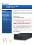
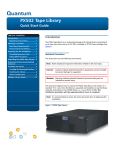
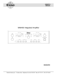
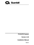
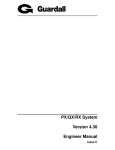
Quantum PX506 and
PX510 Unpacking and
Installation Instructions
Introduction
3
Selecting an Installation Location
4
Rack Space Requirements.........................................................................................5
Environmental Conditions .......................................................................................6
Preparing for the Installation
7
Providing Necessary Tools and Equipment ..........................................................7
Taking ESD Precautions ...........................................................................................7
Unpacking the Library
8
Removing the Remaining Packing Materials
11
Installing the Library
15
Locating the Mounting Position ............................................................................15
Installing the Library...............................................................................................19
Loading the Tape Cartridges .................................................................................32
Initial Configuration................................................................................................32
Installing Additional Libraries
35
Removing the FlexLink Covers .............................................................................36
Installing the Alignment Hardware......................................................................38
Installing the Libraries ............................................................................................39
Configuring the Libraries in a Multiple Stack.....................................................39
Document 81-81338-01 D01, June 2005
1
Quantum PX506 and PX510 Unpacking and Installation Instructions
Document 81-81338-01 D01
June 2005
2
Quantum PX506 and PX510 Unpacking and Installation Instructions
Document 81-81338-01 D01
June 2005
Introduction
0
Caution:
Do NOT unpack the Quantum PX506 or PX510 unless you are
a qualified Quantum field service engineer.
This document explains how to unpack the Quantum PX506 and PX510
libraries and install them in a standard 19 in. rack. Once the library is
unpacked and installed, set up the library using the instructions in the
Quantum PX500 Series User’s Guide PN 81-81290.
The Quantum PX506 and PX510 are automated storage and retrieval libraries
consisting of:
•
up to six tape drives and up to 88 SDLT cartridges or 100 LTO tape
cartridges for the PX506 (see figure 1).
•
up to ten tape drives and up to 171 SDLT or 201 LTO tape cartridges for
the PX510 (see figure 2).
Figure 1 Quantum PX506
Library
Introduction
3
Quantum PX506 and PX510 Unpacking and Installation Instructions
Document 81-81338-01 D01
June 2005
Figure 2 Quantum PX510
Library
Selecting an Installation Location
When choosing an installation site for the PX506 and PX510, consider the
following requirements:
4
•
Rack Space Requirements
•
Environmental Conditions
Selecting an Installation Location
0
Quantum PX506 and PX510 Unpacking and Installation Instructions
Document 81-81338-01 D01
June 2005
Rack Space
Requirements
0
Figure 3 shows the minimum rack space required by both the PX506 and
PX510.
•
Depth - 31 in (76.2 cm)
•
Width - 19 in (48.3 cm)
•
Height:
•
•
PX506 - 17.25 in (44 cm) - 10U per library
•
PX510 - 31.5 in (80 cm) - 18U per library
Weight:
•
PX506 - 202 lbs. (92 kg) with 6 drives, 4 magazines, and 0 cartridges
installed
•
PX510 - 334 lbs. (152 kg) with 10 drives, 10 magazines, and 0
cartridges installed
•
Clearance behind library, inside rack - 6 in (15 cm) for serviceability
•
Door swing - 3 ft (.91 m)
Selecting an Installation Location
5
Quantum PX506 and PX510 Unpacking and Installation Instructions
Document 81-81338-01 D01
June 2005
Figure 3 Rack Space
Requirements
19
31
in (
48 .
3c
in
to
i
36
n(
.
78
o9
8t
m
1c
m)
PX510 shown
Environmental
Conditions
The installation site must have the following environmental conditions:
0
•
Humidity: 20%-80% non-condensing
•
Temperature: 15°C-35°C (59°F-95°F)
•
Altitude: -984 to 10,000 feet (-300 to 3048 meters)
•
PX506 power requirements:
•
6
•
Voltage - 88-264 VAC, 47-63 Hz
•
Watts - 325
PX510 power requirements:
•
Voltage - 88-264 VAC, 47-63 Hz
•
Watts - 500
Selecting an Installation Location
Quantum PX506 and PX510 Unpacking and Installation Instructions
Document 81-81338-01 D01
June 2005
•
Service clearance - 15 in (38 cm) in the front of the library and 12 in (30
cm) in the back of the library
These environmental conditions apply when the PX506 and PX510 libraries
are in operation.
Note:
For additional PX500 Series specifications (including
environmental requirements during shipping and storage), see the
Quantum PX500 Series User’s Guide (PN 81-81290).
Preparing for the Installation
0
Before you begin the installation procedure in this section, make the
following preparations as described in this section:
Providing Necessary
Tools and Equipment 0
Taking ESD
Precautions
0
•
Providing Necessary Tools and Equipment
•
Taking ESD Precautions
Provide the following tools for unpacking and installing the PX506 and PX510
libraries:
•
#2 PHILLIPS® screwdriver
•
Metal pick included in accessory kit
•
Wood dowel included in accessory kit
•
#1 flat blade screwdriver
•
Allen wrench (2.5mm and 3mm) included in accessory kit
•
Antistatic wrist strap
Some components within the PX506 and PX510 libraries contain staticsensitive parts. To avoid damaging these parts while performing installation
procedures, always observe the following precautions:
•
Keep the library turned off during all installation procedures.
•
Use an antistatic wrist strap (included in the accessory kit).
•
Keep static-sensitive parts in their original shipping containers until
ready for installation. Look for the ESD sticker to identify static sensitive
parts.
Preparing for the Installation
7
Quantum PX506 and PX510 Unpacking and Installation Instructions
Document 81-81338-01 D01
June 2005
•
Do not place static-sensitive parts on a metal surface. Place them inside
their protective shipping bag or on an antistatic mat.
•
Avoid touching connectors and other components.
Note:
Dry climates and cold-weather heating environments have lower
relative humidity and are more likely to produce static electricity.
Unpacking the Library
Note:
0
Inspect the outer library packaging for damage. If there is any
damage evident on the library packaging, to not continue with the
installation and contact Quantum customer support.
This section explains how to unpack both the PX506 and PX510 library
components and move them to their final installation location. By following
these instructions, you help ensure that the system will continue to be
safeguarded after it arrives at the installation site.
Note:
Unpack the library as close to the installation location as possible.
Unpack and remove the following components from the packing materials
(see figure 4 for PX506 and figure 5 for PX510):
1 Remove the accessories kit and set it aside.
Warning:
At least two people are required to move the library
chassis.
Caution:
Lift the library chassis at the sides. Avoid putting the
weight of the library chassis on the front bezel.
2 With the help of a second person, lift the library chassis up and out of the
shipping carton.
3 Place the library on a table approximately waist high.
8
Unpacking the Library
Quantum PX506 and PX510 Unpacking and Installation Instructions
Document 81-81338-01 D01
June 2005
Figure 4 Unpacking the
Libraries (PX506)
Cover
Accessories kit
Front bezel
Lift point
Metal bands
Metal bands
Pallet
Unpacking the Library
9
Quantum PX506 and PX510 Unpacking and Installation Instructions
Document 81-81338-01 D01
June 2005
Figure 5 Unpacking the
Libraries (PX510)
Lid
Sleeve
Accessories kit
Front bezel
Lift point
Metal bands
Metal bands
Pallet
10
Unpacking the Library
Quantum PX506 and PX510 Unpacking and Installation Instructions
Document 81-81338-01 D01
June 2005
Removing the Remaining Packing Materials
0
Now that you have removed the library chassis from its shipping carton,
remove the remaining packing materials from the library chassis:
1 Put on an antistatic wrist strap and clip it to the antistatic stud on the back
of the library (near the power supply).
Caution:
Take standard ESD precautions when performing this
procedure.
2 Remove the antistatic sheet:
a
Cut the tape strips securing the sheet.
b
Fold the sheet down.
c
With the help of a second person, lift the library up off of the
antistatic sheet.
d
Place the library on the table or desk next to the antistatic sheet.
3 Insert the metal pick included with the accessory kit into the release holes
and move the magazine door release to the left for all magazine doors
(see figure 6).
The magazine access doors open.
Removing the Remaining Packing Materials
11
Quantum PX506 and PX510 Unpacking and Installation Instructions
Document 81-81338-01 D01
June 2005
Figure 6 Opening the
Right and Left Magazine
Access Doors
Left magazine doors
Right magazine doors
Door releases
4 Insert the wooden dowel that is included in the library accessory kit into
the magazine release hole and trip the magazine release to remove the
each magazine from the library (see figure 7). Remove all magazines from
a PX506 library and the bottom four magazines (two on each side) from a
PX510 library.
12
Note:
Keep the tool as straight as possible when inserting the
wooden dowel into the magazine release hole. You must
continue to hold the tool against the magazine release until the
magazine is entirely out of the library.
Note:
Only the bottom most magazines have a magazine release. All
other magazines can be pulled directly from the library
without a release mechanism.
Removing the Remaining Packing Materials
Quantum PX506 and PX510 Unpacking and Installation Instructions
Document 81-81338-01 D01
June 2005
Figure 7 Removing the
Magazines
Magazine release hole
Magazine release
Magazine release
(engaged)
Right magazine
PX506 shown
Removing the Remaining Packing Materials
13
Quantum PX506 and PX510 Unpacking and Installation Instructions
Document 81-81338-01 D01
June 2005
5 To remove the robotics restraints (see figure 8):
a
Disconnect the two velcro straps securing the robotics restraints to
the library chassis.
b
Pull the straps away from the chassis anchors and remove the straps
from the library.
c
Lift the left robotics restraint slightly up and remove it from the
library.
d
Slide the right robotics restraint to the right until you are clear of the
robotics motor and remove the restraint from the library.
Caution:
Avoid touching the printed circuit board and ribbon cable
connectors on the robotic hand.
Figure 8 Removing the
Robotics Restraints
Velcro straps
Left door
Robotics
restraints
Note:
14
Right door
PX506 shown
PX506 shown
Save the robotics restraints for later shipping or relocation of
the library.
Removing the Remaining Packing Materials
Quantum PX506 and PX510 Unpacking and Installation Instructions
Document 81-81338-01 D01
June 2005
Close the front doors.
e
6 Remove the tape drive cover plates by loosening the captive screws
securing the plate to the library chassis with a flat blade screwdriver (see
figure 9).
Figure 9 Removing the
Tape Drive Cover Plates
Tape
drive 1
Tape
drive 3
Tape
drive 2
Tape
drive 5
Tape
drive 4
Cover plate
Tape
drive 6
Installing the Library
0
Installing a PX506 and PX510 library in a rack consists of the following steps:
Note:
Locating the Mounting
Position
0
If this is an upgrade to an existing library system or multiple
libraries are going to be installed in this rack, see Installing
Additional Libraries on page 35 for information on preparing the
library chassis prior to installation.
•
Locating the Mounting Position
•
Installing the Library
•
Loading the Tape Cartridges
•
Initial Configuration
Both the PX506 and PX510 libraries are designed to fit in a standard 19 inch
wide rack.
Installing the Library
15
Quantum PX506 and PX510 Unpacking and Installation Instructions
Document 81-81338-01 D01
June 2005
It is important to the library installation to locate the hole pattern in the rack
rails (see figure 11). The library must be installed at the beginning of the hole
pattern. Refer to table 1 for information on common rack hole types.
Table 1 Rack Hole Types
Figure
Description
Cage nut
Square rack holes are the most common type of rack
holes. They can accept either cage nuts which mount
from the back of the rail or clip nuts which clip on from
the side of the rack rail.
Clip nut
Clip nut
Through holes require clip nuts to accept mounting
hardware.
Threaded holes require neither cage or clip nuts to
accept mounting hardware.
Note:
16
The rails within the rack have a hole pattern that repeats
throughout the rail. X marks the screw positions. Install nut clips
(included in the accessory kit) on the rails if necessary.
Installing the Library
Quantum PX506 and PX510 Unpacking and Installation Instructions
Document 81-81338-01 D01
June 2005
Figure 10 PX506 Rail Hole
Patterns and Mounting
Positions
)URQWSDQHO
VFUHZV
8 LQ
PP
)URQWSDQHO
VFUHZV
%DFNSDQHO
VFUHZV
%DFNSDQHO
VFU HZV
LQPP
LQPP
LQPP
LQPP
LQPP
LQPP
LQPP
)URQWSDQHOVFUHZV XVHGWR
VHFXUHWKHOLEUDU\WRWKHU DFN
UDLOV
%DFNSDQHOVFUHZVXVHGWR
VHFXUHWKHOLEUDU\P RXQWLQJ
VKHOYHVWRWKHEDFNRIWKHUDFN
UDLOV
8RIUDFNVSDFH
+ROHSDWWHUQ
7RSRIUDFN
)URQWSDQHO
VFUHZV
)URQWSDQHO
VFUHZV
Installing the Library
17
Quantum PX506 and PX510 Unpacking and Installation Instructions
Document 81-81338-01 D01
June 2005
Figure 11 PX510 Rail Hole
Pattern and Mounting
Positions
)U RQWSDQHO
VFUHZV
8 LQ
PP
%DFNSDQHO
VFU HZV
%DFNSDQHO
VFUHZV
+ROHSDWWHUQ
7RSRIUDFN
LQPP
LQP P
8RIUDFNVSDFH
)U RQWSDQHO
VFUHZV
LQP P
LQPP
LQP P
LQP P
LQPP
)U RQWSDQHO
VFUHZV
)U RQWSDQHO
VFUHZV
)URQWSDQHOVFUHZV XVHGWR
VHFXUHWKHOLEUDU\WRWKHUDFN
UDLOV
%DFNSDQHOVFUHZVXVHGWR
VHFXUHWKHOLEUDU\PRXQWLQJ
VKHOYHVWRWKHEDFNRIWKHUDFN
UDLOV
18
)U RQWSDQHO
VFUHZV
Installing the Library
Quantum PX506 and PX510 Unpacking and Installation Instructions
Document 81-81338-01 D01
June 2005
Warning:
Installing the Library 0
Table 2 Library Mounting
Hardware
If the rack is empty at the time of installation, do NOT install
the PX506 or PX510 library too high in the rack. The weight of
the libraries may cause the rack to become “top heavy” and
unstable if installed in the top of an empty rack. If multiple
libraries are to be installed in the rack, begin the library
installations from the bottom of the rack.
Installing the PX506 and PX510 libraries consists of the following steps:
•
Installing the Rack Mount Shelves
•
Installing the Library Chassis
•
Cabling the Library
Qty
Figure
Description
16
Allen head screws (M5 x 10) for shelf
assembly
8
T- nuts (M5)
4
Rail adapters (both metric and standard holes
are included, 8 total adapters)
2
Right and left support shelves (left shown)
4
sets
Front and back rail mounting hardware
(M5 x 12 allen screws and mounting plates)
Installing the Library
19
Quantum PX506 and PX510 Unpacking and Installation Instructions
Document 81-81338-01 D01
June 2005
Qty
Figure
Description
2
sets
Back bracket hardware (M5 x 8 allen screws
and mounting plate)
2
sets
Back clamp hardware (M5 x 10 and back
clamp)
Installing the Rack Mount Shelves
0
1 Assemble the rack mount shelves by (see figure 13):
Note:
The rack mount shelf orientation differs between the right and left
shelves to allow the FlexLink system to operate.
Loosely attach the adjustable shelves (right and left) with 4 M5 x 10
Allen screws and T-nuts.
a
Note:
b
20
T-Nuts must be oriented so they fit in the grooves of the
shelves.
Attach the appropriate rail adapter to the front and back of the rack
mount shelves (right and left) with 4 M5 x 10 Allen screws (each rail
adapter is marked with the specific hole type supported, either metric
or standard). The rail adapters have arrows indicating the proper
orientation (see figure 12).
Installing the Library
Quantum PX506 and PX510 Unpacking and Installation Instructions
Document 81-81338-01 D01
June 2005
Figure 12 Rail Adapter
Orientation
Keep the arrow up for
correct orientation
Figure 13 Assembling the
Rack Mount Shelves
Allen screws
Rail adapter
Rail adapter
T-nuts
T-nuts
Right rail
Left rail
Rail adapter
Rail adapter
2 Install the left and right rack mount shelves into the rack (the rack mount
shelves adjust 27 in. to 36 in.) and secure with a mounting plate and 2 M4
x 12 Allen screws at the front and back of the rack (see figure 14).
Note:
The rack mount shelves must be installed on the inside rack
rails.
Installing the Library
21
Quantum PX506 and PX510 Unpacking and Installation Instructions
Document 81-81338-01 D01
June 2005
Figure 14 Installing the
Rack Mount Shelves
Mounting
plate
M4 x 12 Allen
screws
Left rack mount shelf
Fr
on
t
of
r
ac
k
Right rack mount shelf
3 Once the rack mount shelves are secured to the rack, tighten the Allen
screws securing the adjustable shelves together.
Installing the Library Chassis
Warning:
The PX506 weighs approximately 78 lbs (35 kg) without power
supplies or tape drives. The PX510 weighs approximately 112
lbs (51 kg) without power supplies or tape drives.At least two
people are required to lift and install either library.
1 Remove the power supplies prior to installing the library to reduce the
weight. Use a flat blade screwdriver to loosen the captive screws and
remove the power supplies (two power supplies in a PX506 and six in a
PX510) from the library (see figure 15).
22
Installing the Library
0
Quantum PX506 and PX510 Unpacking and Installation Instructions
Document 81-81338-01 D01
June 2005
Figure 15 Removing the
Power Supplies
Captive
screw
PX510 shown
2 The back mounting brackets are lettered (A through I) so the correct
mounting position is easily determined. The mounting positions differ
depending on the depth of the rack (see table 3).
Installing the Library
23
Quantum PX506 and PX510 Unpacking and Installation Instructions
Document 81-81338-01 D01
June 2005
Table 3 Back Mounting
Bracket Orientation
Rack Depth
Mounting Position
> 27 to 28 in.
Use holes A and C
> 28 to 29 in.
Use holes B and D
> 29 to 30 in.
Use holes A and C
> 30 to 31 in.
Use holes B and D
> 31 to 32 in.
Use holes C and E
> 32 to 33 in.
Use holes D and F
> 33 to 34 in.
Use holes E and G
> 34 to 35 in.
Use holes F and H
> 35 to 36 in.
Use holes G and I
Once the location is determined, attach the back brackets to each side of the
library with four M5 x 8 Allen screws (see figure 16 for the PX506 and
figure 17 for the PX510).
24
Note:
Use the shortest depth number. For example, if the measurement
is 34 in., use holes E and G.
Note:
If this is a multiple stack configuration, refer to Installing
Additional Libraries on page 35 for information on preparing the
library chassis for passing tape cartridges from one unit to another.
Installing the Library
Quantum PX506 and PX510 Unpacking and Installation Instructions
Document 81-81338-01 D01
June 2005
Figure 16 Back Mounting
Brackets (PX506)
Back mounting
bracket
Back mounting
bracket
Allen screws
Allen screws
Figure 17 Back Mounting
Brackets (PX510)
Back mounting
bracket
Back mounting
bracket
Allen screws
Allen screws
3 Install the library into the rack as shown and secure with eight PHILLIPS
screws for the PX506 and twelve PHILLIPS screws for the PX510 (see
figure 18 for the PX506 and figure 19 for the PX510).
Warning:
The PX506 weighs approximately 78 lbs (35 kg) without
power supplies or tape drives. The PX510 weighs
approximately 112 lbs (51 kg) without power supplies or
tape drives.At least two people are required to lift and
install either library.
Installing the Library
25
Quantum PX506 and PX510 Unpacking and Installation Instructions
Document 81-81338-01 D01
June 2005
Figure 18 Installing the
Library into the Rack
PHILLIPS screws
Fr
on
to
fr
ac
k
Figure 19 Installing the
Library into the Rack
PHILLIPS screws
Fr
26
Installing the Library
on
t
of
rac
k
Quantum PX506 and PX510 Unpacking and Installation Instructions
Document 81-81338-01 D01
June 2005
4 Secure the back of the library to the rack with two mounting clamps and
and two Allen screws on each clamp. The mounting clamps are oriented
differently depending on the depth of the rack (see figure 20).
Note:
If the rack depth is 27 to 30 in., the long portion of the clamp is
mounted to the back. If the rack depth is 30 to 36 in., the long
portion is mounted to the front.
5 Secure the mounting clamps to the rack rails with two PHILLIPS screws
on each side (see figure 20).
Figure 20 Securing the
Back of the Library
Allen
screws
Ba
c
k
of
ra
ck
Long
portion
PHILLIPS
screws
PX506 shown
6 Install the power supplies previously removed. Tighten the captive
screws with a flat blade screw driver.
7 To install the tape drives into the library:
a
Remove the tape drive cover plates by loosening the captive screws
securing the plate to the library chassis with a flat blade screwdriver
(see figure 21).
Installing the Library
27
Quantum PX506 and PX510 Unpacking and Installation Instructions
Document 81-81338-01 D01
June 2005
Figure 21 Removing the
Tape Drive Cover Plates
Tape
drive 1
Tape
drive 3
Tape
drive 2
Tape
drive 5
Tape
drive 4
Cover plate
Tape
drive 6
PX506 shown
b
Insert the tape drive into the drive bay slowly until the connectors are
seated. Refer to figure 22 and figure 23 for drive bay numbering.
Figure 22 PX506 Tape
Drive Numbering
Tape
drive 2
Tape
drive 1
Tape
drive 4
Tape
drive 3
Tape
drive 6
28
Tape
drive 5
Installing the Library
Quantum PX506 and PX510 Unpacking and Installation Instructions
Document 81-81338-01 D01
June 2005
Figure 23 PX510 Tape
Drive Numbering
Tape
drive 2
Tape
drive 1
Tape
drive 4
Tape
drive 3
Tape
drive 6
Tape
drive 5
Tape
drive 8
Tape
drive 7
Tape
drive 10
Tape
drive 9
c
Tighten the tape drive thumbscrews using a flat blade screwdriver.
d
Repeat these steps to install another tape drive in a different location,
if desired.
The library chassis is installed in the rack.
0
Cabling the Library
1 Connect the SCSI cables and jumpers as shown in the following figures:
Note:
•
For Fibre Channel bridge installation and cabling instructions,
refer to the Quantum FC1202 Installation Instructions (PN 81-81371).
PX506 Cabling Configuration (SCSI)
Installing the Library
29
Quantum PX506 and PX510 Unpacking and Installation Instructions
Document 81-81338-01 D01
June 2005
•
PX510 Cabling Configuration (SCSI)
Note:
Quantum ships sufficient SCSI cables and terminators with the
libraries to set up two-drives per SCSI bus. One tape drive per
SCSI bus may be necessary for optimum performance. Refer to
your tape drive documentation.
Note:
SCSI cable lengths should not exceed 82 feet (25 meters) between
the host and library.
Figure 24 PX506 Cabling
Configuration (SCSI)
SCSI
jumper
Host computer
Network
SCSI jumper
Host computer
SCSI
terminators
SCSI jumper
Host computer
SCSI jumper
30
Installing the Library
Quantum PX506 and PX510 Unpacking and Installation Instructions
Document 81-81338-01 D01
June 2005
Figure 25 PX510 Cabling
Configuration (SCSI)
SCSI
jumper
SCSI jumper
Host computer
Host computer
SCSI
jumper
Host computer
SCSI
jumper
SCSI
terminators
Host computer
SCSI
jumper
Host computer
2 Connect one end of an AC power cable to each installed power supply
and to a wall outlet.
Installing the Library
31
Quantum PX506 and PX510 Unpacking and Installation Instructions
Document 81-81338-01 D01
June 2005
Loading the Tape
Cartridges
0
Initial Configuration 0
Before operating the library, load the appropriate tape cartridges (LTO and/
or SDLT) into the library starting with the left-hand magazines (refer to the
Quantum PX500 Series User’s Guide PN 81-8290 for more information on tape
cartridges).
Initially configuring the library consists of the following steps:
•
Turning on the Library
•
Setting the Library Options
•
Setting the Date and Time
•
Setting Network Information
0
Turning on the Library
To turn on the library:
1 Verify that:
•
Power cables are firmly in place
•
All doors are closed
2 Push the power button located behind the OCP cover (see figure 26).
Figure 26 Turning On the
Library
OCP
Power button
During the power up sequence, the library performs an inventory. The
power up sequence can take several minutes.
32
Installing the Library
Quantum PX506 and PX510 Unpacking and Installation Instructions
Document 81-81338-01 D01
June 2005
0
Setting the Library Options
To set the library options:
1 Press Setup from the Home screen. The OCP displays the Setup screen
(see figure 27):
Figure 27 Setup Screen
Enter
2 From the Setup screen, use the up and down arrows to highlight Cabinet
and press Enter.
The Cabinet screen displays (see figure 28):
Figure 28 Library Options
Screen
3 The Stack role screen allows you to configure the library as a “Master” or
“Slave” in a multiple library stack. The library is configured “Stand
alone” by default. If this is a multiple library stack, use the up and down
arrows to highlight Stack role and press Enter and the OCP displays the
following information about the library:
Installing the Library
33
Quantum PX506 and PX510 Unpacking and Installation Instructions
Document 81-81338-01 D01
June 2005
Table 4 Setting Up the
Cabinet
Cabinet Options
Description
Host bus
Sets the SCSI ID for both the library
and tape drives.
Stack role
Assigns the library stack role as
Master, Slave, or Stand alone. There
can be only one Master library in a
multiple stack. Once configured as a
slave, all library OCP functions can be
controlled via the Master library OCP.
The library model number will also
change to PX500S indicating a stacked
library configuration. The library
model number is available from the
home screen on the Master library
OCP.
Left load port
Enables or disables the left load port
Right load port
Enables or disables the right load port
Auto inventory
Enables or disables the auto inventory
function. When enabled, the library
automatically inventories the library
contents when going “On-line”.
Setting the Date and Time
0
To set the date and time:
1 From the Setup screen, use the up and down arrows to highlight Date and
Time and press Enter.
The Date and Time screen displays (see figure 29):
Figure 29 Date and Time
Screen
The Date and Time screen displays the following information about the
library:
2 Use the up and down arrows to view or edit the date and time
information. Press Enter to accept the new settings.
3 When you are finished viewing/editing the date and time information,
press Exit to return to the Setup screen.
34
Installing the Library
Quantum PX506 and PX510 Unpacking and Installation Instructions
Document 81-81338-01 D01
June 2005
Setting Network Information
0
To view or edit the network information:
1 From the Setup screen, use the up and down arrows to highlight Network
and press Enter.
The Network screen displays (see figure 29):
Figure 30 Network Screen
The Network screen allows you to view or edit the following network
settings:
•
DHCP
•
IP address
•
Subnet mask
•
Default gateway
2 Use the up and down arrows to select the network setting you wish to
view or edit and press Enter.
When you are finished viewing/editing the network information, press
Back to return to the Setup screen. The library is initially configured and
ready for use. Refer to the PX500 Series User’s Guide (PN 81-81290) for
information on diagnostic tests.
Note:
Close the service call and register the installation with
Quantum customer support.
Installing Additional Libraries
0
The PX506 and PX510 library modules can be used as stand-alone libraries, or
combined with other PX500 Series library modules in a standard 19-inch rack
to form a larger library system (called a multiple library stack). The multiple
library stack appears as a single large capacity library to the host and can pass
cartridges through the library.
Installing additional libraries and configuring for a multiple library stack
consists of the following steps:
•
Removing the FlexLink Covers
Installing Additional Libraries
35
Quantum PX506 and PX510 Unpacking and Installation Instructions
Document 81-81338-01 D01
June 2005
Removing the FlexLink
Covers
0
•
Installing the Libraries
•
Configuring the Libraries in a Multiple Stack
The FlexLink covers must be removed prior to library installation so tape
cartridges can pass between library chassis.
To remove the FlexLink covers:
1 The library modules have pass-through cover plates located on the top
and bottom of the chassis. Depending on the location of the library in the
stack, one or both of the cover plates are removed from the chassis (see
figure 31).
Figure 31 Identifying the
Cover Plates for Removal
Library 1
Top library in stack - remove ONLY the
bottom cover plate
Library 2
Middle library in stack - remove BOTH the
top and bottom cover plate
Library 3
Middle library in stack - remove BOTH the
top and bottom cover plate
Library 4
Bottom library in stack - remove ONLY the
top cover plate
2 After you have identified the cover plates to remove, use a #2 PHILLIPS
screwdriver to remove the two screws that secure the cover plate to the
library chassis (see figure 32).
Note:
36
The cover plate location is the same on both the PX506 and
PX510 libraries.
Installing Additional Libraries
Quantum PX506 and PX510 Unpacking and Installation Instructions
Document 81-81338-01 D01
June 2005
Figure 32 Removing the
Pass-through Cover Plates
Infrared
transmitter/
receiver
Screws
Cover plate
Cover plate
Screws
Infrared
transmitter/
receiver
PX506 shown
The cover plates are removed.
Installing Additional Libraries
37
Quantum PX506 and PX510 Unpacking and Installation Instructions
Document 81-81338-01 D01
June 2005
Installing the
Alignment Hardware 0
The alignment hardware is installed on the top and bottom of the libraries in a
multiple stack to allow the FlexLink bays to align correctly.
Install the following alignment hardware (see figure 33):
1 Install the top alignment hardware with two PHILLIPS screws.
2 Install the bottom alignment hardware with one PHILLIPS screw.
Note:
Install only the bottom alignment hardware on the top library
in the stack and the top alignment hardware on the bottom
library in the stack.
Screws
Figure 33 Installing the
Alignment Hardware
Top alignment hardware
Bottom alignment hardware
Screws
The libraries are prepared for installation in a multiple stack.
38
Installing Additional Libraries
Quantum PX506 and PX510 Unpacking and Installation Instructions
Document 81-81338-01 D01
June 2005
Installing the Libraries 0
Refer to Installing the Library on page 15 for information on installing the
library chassis into the rack. The libraries must be stacked without space
between units.
Configuring the Libraries
in a Multiple Stack
0
The libraries initialize by default in a “Stand Alone” configuration. The
libraries must be set to either a “Master” or “Slave” configuration through the
OCP so the libraries recognize the other units in the stack.
To configure the libraries in a multiple stack:
1 Select one of the libraries in the stack to be the “Master” library. This
library can occupy any position in the stack.
2 Refer to Setting the Library Options on page 33 for information on setting
the library’s stack role.
Installing Additional Libraries
39
Quantum PX506 and PX510 Unpacking and Installation Instructions
Document 81-81338-01 D01
June 2005
40
Installing Additional Libraries