1
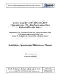
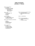
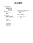
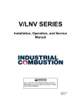
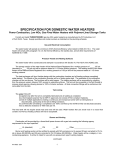
PVI ATMOSPHERIC GAS WATER HEATERS TYPICAL CONSTRUCTION MANUFACTURED AFTER JANUARY 1, 1994 Figure 2-1 1. 2. 3. 4. 5. 6. Vent stack * Draft diverter (hood) Flue damper (on some models) Temperature limiting device (set at 200°F) Upper operating thermostat (set at 130°F) Operating thermostat (set at 120°F) 7. 8. 9. 10. 11. 12. Control switch(es) and fuse(s) Gas valve Pilot line Drip leg * Gas supply line * Handhole cleanout (* Not furnished by PVI) CAUTION: TEMPERATURES HIGHER THAN 125°F INCREASE THE RISK OF SCALD INJURY! IMPORTANT: Clearances to unprotected combustible material must be 8" minimum at top, sides and rear, and 24" in front. Clearances for servicing and inspection must be 18" minimum at sides and rear and 24" minimum in front. PV500-2 06/10 1 Section 2 ELECTRICAL Typical 24 Volt Control System with Damper 1. Wiring to the unit should conform to the National Electrical Code or the code legally authorized in your locality. A fused disconnect switch should be used for the water heater control. 120V, 1ph, 60 Hz service wiring is brought to the terminal block in the lower part of the enclosure on the water heater. See Figures 22, 2-3 and 2-4. FOR YOUR SAFETY USE ONLY COPPER WIRE OF PROPER SIZING FOR INCOMING SERVICE. DAMAGE RESULTING FROM USE OF ALUMINUM WIRING WILL BE EXCLUDED FROM COVERAGE UNDER THE WARRANTY OF THIS UNIT. Typical 24 Volt Control System Figure 2-3 Typical 120 Volt Control System Figure 2-2 Figure 2-4 PV500-2 06/10 2 Section 2 START-UP PROCEDURES AND OPERATION 3. Remove the control box cover to access the control thermostats and other electrical devices needed to operate the water heater. The thermostats are labeled as to their function. The temperature limiting device is set at 200°F. The thermostats are factory set at 130°F. (the upper operating thermostat) and 120°F (the operating thermostat). Adjustment may be made by turning the thermostat dial to the desired temperature. 1. Some PVI atmospheric gas-fired water heaters are designed to operate with a flue damper that is shipped with the water heater for installation in the field. If your water heater was shipped with a flue damper, it must be attached to the flue collector and interconnected to the ignition control module before proceeding with start-up. Flue Damper Installation CAUTION: BE SURE TO REATTACH THE CONTROL BOX COVER TO HELP PREVENT UNAUTHORIZED ACCESS TO CONTROLS. a. Set the flue damper over the flue collector opening and align the damper drive housing to the front of the heater. CAUTION: DO NOT OVERTIGHTEN COMPRESSION FITTINGS ON THERMOSTAT BULBS AS CALIBRATION WILL BE CHANGED. b. Secure the flue damper to the flue collector at three locations using the fasteners provided. c. Remove the damper drive housing cover, feed the damper interconnect cable through the access hole and attach the female connector to the four-pin receptacle. Secure the access hole cover, check to make sure the test switch is in the "NORMAL" position, and reattach the damper driver housing cover. CAUTION: TEMPERATURES HIGHER THAN 125°F INCREASE THE RISK OF SCALD INJURY! Gas Train Safety Inspection CAUTION: ALL VENTED GAS CONTROLS MUST BE VENTED TO THE OUTSIDE USING TUBING SIZED IN ACCORDANCE WITH THE FOLLOWING TABLE: CAUTION: BE SURE THERE IS NO FOREIGN MATTER IN THE DAMPER HOUSING BEFORE ATTACHING THE DRAFT DIVERTER. VENT LINE SIZING Draft Diverter Installation The draft diverter (provided) is designed to mount on top of the flue damper. Set the draft diverter on top of the flue damper and secure in three locations using the fasteners provided. Venting Type B galvanized vent pipe, of the same diameter as the draft diverter outlet, must be installed to route combustion products either to existing overhead breeching or to an appropriate outside location. Fuel Line Size, Nominal Pipe Size, Inches Up to 1 1/2 Vent Line Size, Nominal Pipe Size, Inches 3/4 2 1 2 1/2 1 1/4 3 1 1/4 4 2 5 2 6 2 1/2 8 3 1. The control manufacturer's installation and service manual and start-up procedures for the control system on your water heater are shipped with the unit. Study the information carefully and follow the manufacturer's recommendations. 2. Fill the water heater tank with water. Open the relief valve or a nearby hot water faucet to allow air in the tank to escape. Be sure all connections into the tank are tight as leaks at tank fittings will damage the insulation. PV500-2 06/10 3 Section 2 START-UP PROCEDURES AND OPERATION (con't) 6. The flue damper is closed. CAUTION: CONDUCT THE FOLLOWING GAS TRAIN LEAKAGE TESTS BEFORE START-UP, AT ANNUAL INTERVALS AND PRIOR TO INVESTIGATING THE CAUSE OF ANY REPORTED OCCURENCES OF DELAYED IGNITION. NOTE: The spark ignition system provides additional safety functions to close the pilot valve if the pilot flame is not established and to close the main burner valve if the pilot flame is extinguished while the burner is in operation. 1. Using an appropriate bubble detection solution, thoroughly coat all gas train pipe connections. If any bubbles are detected, the leaking connection must be tightened and tested to assure stoppage of the leak. 2. Attach a manometer. to measure gas pressure, at manual gas shutoff valve located just upstream of gas train. Adjust gas train inlet pressure to specified value (e.g. 14"W.C.), and tightly close gas train outlet manual shutoff valve. WATER HEATER START-UP NOTE: a. b. c. d. e. f. the the the the 3. Reattach the manometer to the gas train outlet manual shutoff valve and record the measured gas pressure in inches of water column (in W.C.). Measure gas pressure again after 15 minutes. If gas pressure has increased 00.5"W.C. or more, the gas leak must be isolated to one or more of the operating gas valves, for example a solenoid actuated gas shutoff valve. After any leaking valve is replaced, the reassembled gas train must be leak tested again before start-up is attempted. (NOTE: All gas valves removed because of suspected leakage must be returned to PVI Customer Service for disposition.) The following test equipment is required: Vent temperature gauge Manometer for checking gas pressure Draft gauge for checking draft in vent CO (carbon monoxide) tester CO2(carbon dioxide) or O2 (oxygen) tester Drill and ¼" drill bit for ¼" hole drilled in vent approximately 12" above draft hood outlet NOTE: Emergency shutoff can be made by turning off the fuel inlet shutoff valve. CAUTION: DO NOT START BURNER WITH COMBUSTION CHAMBER FULL OF GAS OR WITH VERY HOT COMBUSTION CHAMBER. The following steps must be performed to assure that the water heater is operating safely and efficiently. 1. Read the enclosed control manufacturer's instruction sheet for start-up procedure. Allowing the pilot to ignite with the main burner gas valve turned to "off" position is required at initial start-up. The pilot flame can be visually checked for size and position. Check inlet gas pressure. It must not exceed 14"W.C. Press the control circuit switch on the front panel to "on" position. The control system will open the pilot valve allowing the pilot to ignite. Observe pilot flame. If satisfactory, open the main burner valve and main burner should ignite. Spark Ignition Systems These systems use 120 VAC power from an external source and are equipped with transformers to reduce the voltage to 24 volts to actuate the gas valve. At start-up or during operation when the thermostat calls for heat, the spark ignition system performs the following basic steps: 1. Opens the flue damper. Pilot and main burner flames can be observed during adjustment and under operating conditions by using the stainless steel hand-held inspection mirror that is enclosed in the information packet that was shipped with this water heater. 2. Activates a high voltage transformer to supply a sparking action to the pilot. 3. Opens the pilot gas valve. The pilot gas ignites from the sparking. If the spark ignition fails to ignite the pilot flame, refer to the control manufacturer's manual supplied with the unit. 4. A sensor located in the pilot flame signals the control module to open the main burner gas valve. The pilot flame ignites the main burner gas. An adequate pilot flame must be present before the main burner gas valve can open. 2. Check gas pressure at the gas valve with a manometer. (See Figure 2-5.) Most gas valves have pressure taps for this purpose. Adjust gas pressure to the value shown on rating plate of the water heater. 5. When the water temperature reaches the operating thermostat setting, the control circuit opens which closes both the pilot and main burner gas valves terminating burner operation. PV500-2 06/10 3. Drill ¼" diameter hole in vent about 12" above draft diverter. Insert draft gauge in drilled ¼" hole. Draft in vent should be -.02" -.06" W.C. 4 Section 2 4. After 20 to 30 minutes of operation or when water in the tank is above 120°F, insert CO (carbon monoxide) tester in flue damper opening under the draft diverter (125 gallon models) or in the flue collector opening (250 gallon models). CO reading must be less than .02% (or 200 ppm). COMBINATION GAS VALVE 5. Insert CO2 (carbon dioxide) tester in the flue damper opening under the draft diverter (125 gallon models) or in the flue collector opening (250 gallon models) and take reading. CO2 should be 6 to 8%. NOTE: Monitoring CO and CO2 readings in vent after the draft diverter will give erroneous readings. These measurements must be taken as flue gases exit the heater flue collector under the draft diverter as dilution with ambient air from the draft diverter occurs in the vent. 6. Insert temperature gauge in ¼" hole and read vent temperature. Temperature should be at least 300°F but less than the room temperature plus 400°F when the water temperature is approximately 130°F. Figure 2-5 7. Connect micro-amp meter as shown in Figure 2-6 and check micro-amps. A minimum of two micro-amps is required for proper operation. MICRO-AMP METER HOOK-UP 8. Record the following information for future use: A. Inlet gas pressure ________________"W.C. B. Gas pressure, manifold (step 2) _____ "W.C. C. Vent draft (step 3) ________________"W.C. (should be minimum of 1 in. W.C.) D. CO reading (step 4) ______% (less than .02%) E. CO2 reading (step 5) __________% (6-8%) F. Vent gas temperature (step 6) Gross__________________F. Figure 2-6 Less Ambient____________°F. Net____________________°F. G. Micro-amps reading (step 7)______________. PV500-2 06/10 5 Section 2 MAINTENANCE AND SAFETY INSPECTIONS To Minimize Scale Accumulation in Tank Periodic Inspection of Operational Components 1. A preventative maintenance program should be established to assure a long, trouble-free life of the water heater. Periodic inspections and check-out of the burner ignition system, control system and gas valve operation should be made and recorded for future reference. 2. The tank should be flushed at two or three month intervals depending on water conditions in your location. To flush, turn off the electrical disconnect switch to prevent the burner from operating. Open the drain valve and allow water to flow through the tank until it runs clear. Close the drain valve and turn the electrical switch back on. Draining two or three gallons from the bottom of the tank on a weekly basis will also help prevent an accumulation of sediment. Water impurities can consist of fine particles of soil or sand which will settle out and form a layer of sediment on the bottom of the tank. 1. Pilot assemblies should be checked by a qualified serviceman using control manufacturer's instructions. Wiring connections on the ignition high voltage wire and flame sensor wire must be tight. Clearance between these wires and metal parts of the water heater or burner must be maintained to avoid possible shorting out. Positions of the electrode, flame sensor and pilot flames are very important and have been set by the manufacturer. If they are loose or if ceramic insulators are cracked or broken, replace the pilot assembly. To replace, remove pilot bracket from bottom of burner, disconnect the pilot gas line and replace pilot assembly on pilot bracket. Replace in reverse order. Do not bend or distort pilot bracket as this determines pilot flame position relative to burner orifices. (See Figure 2-7). Inspect individual burner jets for evidence of overheating. Replace burner jets as necessary. A scale of lime will normally form in the tank during operation and will accumulate on the bottom of the tank. Lime is formed from the natural chemicals in the water which precipitate out during the heating cycles. Some water supplies contain more of these elements than others, and the scale buildup will occur more rapidly. Other factors affecting the scale buildup are the amount of hot water used and the water temperature. As more hot water is used, the more fresh water containing the scale-forming elements is brought into the tank. As the temperature of the water increases, the rate of scale deposition will be increased. 2. Examine the venting system at least quarterly for proper connections, alignment and the presence of corrosion. Any corroded vent section should be immediately replaced to prevent CO leakage. Recheck vent temperature (step 6, page 5) and correct if necessary. Sediment and scale accumulations in the tank will greatly reduce the water heating ability of the heater by reducing effectiveness of heat transfer surfaces. When heating energy from the burner cannot be effectively transferred to the water in the tank, the metal can overheat causing it to lose structural strength. CAUTION: THE RELIEF VALVE IS A PRIMARY SAFETY DEVICE. 3. The temperature and pressure relief valve should be removed and inspected at regular intervals to determine its condition for safe operation. The openings inside the valve may become restricted by a buildup of scale and become inoperative. If the valve does not open and close properly when tested, it must be replaced with a like kind or one meeting the requirements stated on the rating tag located on the relief valve. 3. Should a firetube leak for any reason, consult the factory for instructions. Inspect bottom tubesheet on a regular basis to determine if insulation may have pulled away from the tubesheet. Repair or replace as required. 4. Spark ignition system operation should be checked as follows: Flame failure – Close downstream gas train shutoff valve and determine safety shutdown timing. Flame signal – Determine flame signal strength in accordance with step 7 on page 5. NOTE: Condensate coming from the tubes on a cold start is normal and does not indicate a leaking tube. 4. The tank may have a handhole for inspection and cleaning use. The handhole cover should be periodically removed and the tank inspected for scale buildup. If scale is present, it can be loosened with a high-pressure stream of water. The smaller pieces can be flushed through the drain and the larger pieces removed by hand through the handhole. The frequency of inspections should be determined by the rate of scale buildup. We recommend 30-60 day intervals. PV500-2 06/10 6 Section 2 MAINTENANCE AND SAFETY INSPECTIONS (con't) c. Tag power switch(es) indicating that fuel is off and tank is empty. Taking the Water Heater Out of Service Extended shutdown of the appliance and restarting instructions are as follows: a. Turn off all power and fuel supplies. d. To restart, refill tank with water and turn fuel and power switch(es) on. Reset all controls and conduct start-up of the appliance as discussed on preceding pages. b. Drain and flush tank as previously discussed. PILOT LOCATION & REMOVAL SPARK IGNITION SYSTEMS Figure 2-7 PV500-2 06/10 7 Section 2