1
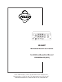
®
MLZA6DT
Motorized Zoom Lens Control
Installation/Operation Manual
C518M Rev B (4/91)
Pelco • 3500 Pelco Way • Clovis, CA 93612-5699 • USA • www.pelco.com
(800) 289-9100 or (1-559) 292-1981 • FAX (800) 289-9150 or (1-559) 292-3827
International customers call (1-559) 292-1981 or FAX (1-559) 348-1120
TABLE OF CONTENTS
Section
Page
1.0
WARNINGS ........................................................................................................................................ 1
2.0
SCOPE ............................................................................................................................................... 2
3.0
DESCRIPTION ................................................................................................................................... 2
3.1 OPTIONS .................................................................................................................................. 2
4.0
INSTALLATION .................................................................................................................................. 3
4.1 CONNECTOR ASSEMBLY ....................................................................................................... 3
4.2 R300 RACK MOUNT KIT INSTALLATION ............................................................................... 5
5.0
OPERATION AND SYSTEM TEST .................................................................................................... 6
5.1 SYSTEM TEST FOR MLZA6DT ............................................................................................... 6
6.0
MAINTENANCE ................................................................................................................................. 7
7.0
SCHEMATIC ...................................................................................................................................... 8
8.0
SPECIFICATIONS ..............................................................................................................................9
LIST OF ILLUSTRATIONS
Figure
1
2
3
4
5
6
Page
Connector Assembly .......................................................................................................................3
Wiring Diagram for Output Pin Assignments ................................................................................... 4
R300 Rack Mount Kit Installation .................................................................................................... 5
Basic System Configuration ............................................................................................................ 6
MLZA6DT Schematic ...................................................................................................................... 8
MLZA6DT Dimension Drawing ........................................................................................................ 9
Pelco, the Pelco Logo, Camclosure, Esprit, Genex, Legacy, and Spectra are registered trademarks of Pelco.
Endura and ExSite are trademarks of Pelco.
ii
© Copyright 1991, Pelco. All rights reserved.
Pelco Manual C518M Rev B (4/91)
INSTALLATION/OPERATION MANUAL
MODEL MLZA6DT
MOTORIZED ZOOM LENS CONTROL
1.0 WARNINGS
Prior to installation and use of this product, the following
WARNINGS should be observed.
4.
Only use replacement parts recommended by
Pelco.
1.
Installation and servicing should only be done by
Qualified Service Personnel and conform to all Local codes.
5.
2.
Unless the unit is specifically marked as a NEMA
Type 3, 3R, 35, 4, 4X, 6 or 6P enclosure, it is designed for Indoor use only and it must not be installed where exposed to rain and moisture.
After replacement/repair of this unit’s electrical
components, conduct a resistance measurement
between line and exposed parts to verify the exposed parts have not been connected to line circuitry.
3.
The product may bear the following marks:
This symbol indicates that dangerous voltage
constituting a risk of electric shock is present
within this unit.
This symbol indicates that there are important
operating and maintenance instructions in the
literature accompanying this unit.
CAUTION:
TO REDUCE THE RISK OF ELECTRICAL
SHOCK, DO NOT REMOVE COVER. NO
USER-SERVICEABLE PARTS INSIDE.
REFER SERVICING TO QUALIFIED
SERVICE PERSONNEL.
CAUTION:
RISK OF ELECTRIC SHOCK.
DO NOT OPEN.
Please thoroughly familiarize yourself with the information in this manual
prior to installation and operation.
Pelco Manual C518M Rev B (4/91)
1
2.0 SCOPE
The information contained within this manual covers
the MLZA6DT Motorized Zoom Lens Control.
3.0 DESCRIPTION
The MLZA6DT is a desktop zoom lens control with
auto/manual iris control designed for use with all Pelco
motorized zoom lenses with “ND” or “MS” in the model
number. The servo amplifier contained within the control detects the slightest change in video level and drives
the iris motor to open or close the iris to maintain proper
faceplate illumination.
Front panel switches provide control of automatic/
manual iris operation, zoom and focus functions, with
optional manual control of the iris. Speed and video
level are adjustable through the front panel knob controls.
3.1 OPTIONS
R300
2
Rack mount kit for up to three (3)
control modules
Pelco Manual C518M Rev B (4/91)
4.0 INSTALLATION
4.
The contact pins supplied with the mating connector are the “crimp” type which may also be soldered if you so desired (item 4).
5.
After crimping or soldering the contact pins to the
conductors, push them into the proper holes in the
connector until they snap in place.
4.1 CONNECTOR ASSEMBLY
Installation and/or testing will require you to assemble
the connector parts provided. Fabricate the interconnecting cable according to the following steps (reference Figure 1).
1.
Slide part A of the cable clamp (item 1) over the end
of the cable (item 1, part C) with the threaded end
of the cable clamp facing the connector (item 5).
2.
If the cable has a diameter less than 1/2 inch (1.3
cm), slide the rubber boot (item 2) over the end of
the cable and pull through the cable clamp to so
that the boot encases the cable and forms a good
seal.
3.
Strip back the cable jacket approximately 1-1/4
inches (3.2 cm) and separate the individual conductors (item 3).
NOTE: Contacts cannot be removed from the
connector without the use of the appropriate
AMP extraction tool which is available from
Pelco.
6.
Slide part A of the cable clamp toward the connector and screw the parts together. Attach part B (item
1) onto part A and connect both parts with the
screws provided.
7.
Connect the cable assembly to the unit and seat
the connector by twisting the locking collar until it
snaps into position.
Refer to Figure 2 for wiring diagram.
5
1
threaded end of
cable clamp
A
B
C
STEP 1
5
1
FLEXIBLE RUBBER BOOT
A
B
STEP 2
C
2
5 **
3
4
1
A
STRIP 1/8"
B
C
STEPS 3-7
CRIMP
INSULATION
CRIMP
WIRE
OUTSIDE
JACKET
OF CABLE
STRIP 1"
**
ITEM 5 DETAIL
4
1
9
10
2
1
3
5
15
4
8
23
33
37
34
FRONT VIEW
37-PIN CONNECTOR
29
3
9
14
16
22
28
15
20
25
21
28
3
10
1
7
14
26
FRONT VIEW
28-PIN CONNECTOR
11
16
15
FRONT VIEW
16-PIN CONNECTOR
3
1
4
7
4
6
THE MOST COMMONLY USED
CONNECTOR PIN-OUT CONFIGURATIONS ARE SHOWN HERE.
REFERENCE THE CONNECTOR
DRAWING APPLICABLE TO
YOUR SITUATION.
1
6
11
8
14
9
7
12
FRONT VIEW
14-PIN CONNECTOR
FRONT VIEW
9-PIN CONNECTOR
Figure 1. Connector Assembly
Pelco Manual C518M Rev B (4/91)
3
1
3
1
12
14
2
6
3
5
4
10
IRIS
1
RED
13
LENS COM
4
BLK
12
ZOOM
2
WHT
WHT
8
GND
G
*
YEL
11
FOCUS
3
GRN
CONTROL
OUTPUT
(CONA14P)
P3
LENS INPUT
(CONA5M)
*GROUND WIRE IS SOLDERED TO
CONNECTOR HOUSING.
Figure 2. Wiring Diagram for Output Pin Assignments
4
Pelco Manual C518M Rev B (4/91)
4.2 R300 RACK MOUNT KIT
INSTALLATION
5.
Insert the chassis into the rack body; sandwich the
rack body slotted tabs between the chassis and the
front plate, and the chassis and the rear plate.
6.
Repeat steps 1-5 for other units or assembly of the
blank faceplate supplied.
To convert desk top units, perform the following steps
(refer to Figure 3):
7.
Install the two straps sandwiching the slotted tabs
as in Step 4, keeping the bent ends outside the body.
1.
Disconnect the equipment from its power supply.
8.
2.
Remove the feet from the bottom of the unit.
3.
Remove the four (4) screws retaining the cover and
remove the cover from the equipment.
Attach the straps and rack body to the chassis with
two (2) cover screws, when applicable. If no chassis is placed in either side port of the rack, a screw
and nut must be used to attach the strap and body
together.
9.
4.
Loosen the eight (8) screws retaining the front and
rear faceplates.
Align the front and faceplates with each other and
tighten the four (4) screws for each plate.
The R300 Rack Mount Kit holds up to three control
modules. Blank filler panels are provided for less than
three modules.
10. Repeat step eight (8) for the rear plates.
11. Reconnect the unit to its power supply.
Figure 3. R300 Rack Mount Kit Installation
Pelco Manual C518M Rev B (4/91)
5
5.0 OPERATION AND SYSTEM TEST
5.
For Auto operation, put the power switch in the
AUTO/ON position. The IRIS switch should not
operate; ZOOM and FOCUS switches should operate normally. Next, adjust the level of video
using the LEVEL knob on the front panel and
observing the monitor. As the video level is adjusted, the iris should open or close depending on
whether video display is bright or dark.
6.
Test the control for fast and slow speeds of all functions by turning the LENS SPEED knob on the
front panel and observing their operation as the
knob is adjusted.
5.1 SYSTEM TEST FOR MLZA6DT
1.
Hook up the cable between the output connector
on the MLZA6DT and the input connector on the
lens (see Figure 4).
2.
Connect the video cable from the camera to the
VIDEO LOOP-THRU on the rear panel and to the
monitor (see Figure 4).
3.
Turn the power switch on the MLZA6DT to the
OFF position, and plug the power cord into a 120
VAC power source.
4.
For MANUAL operation, put the power switch in
the MAN position. Observing the monitor, test for
proper operation of zoom, focus, and iris functions
with related switches on the front panel.
COAX CABLE
CONTROL CABLE
MLZA6
Figure 4. Basic System Configuration
6
Pelco Manual C518M Rev B (4/91)
6.0 MAINTENANCE
Under normal operating conditions and usage, maintenance of this equipment is not necessary. However, if
maintenance should be required, consult Pelco or a
qualified service technician.
NOTE: Pelco offers a 24-hour, seven-daysa-week Technical Assistance Program (TAP)
designed to assist any customer with a technical problem involving Pelco equipment whether
it’s the weekend or late at night. For technical
assistance dial (800) 289-9100 and you will
be connected to a Pelco TAP member who is
trained to answer your questions.
Pelco also guarantees one-day turnaround on
any Pelco equipment sent in for repair. This
includes warranty and non-warranty items.
Refer to the section on “Warranty and Return
Information” in this manual for the proper procedure.
Pelco Manual C518M Rev B (4/91)
7
8
AC
INPUT
POWER ON
AUTO IRIS
PADDLE
UP
WHT
BLK
GRN
8
5
2
POWER ON
MAN IRIS
10 7 4 1
11
12 9 6 3
PADDLE
CENTER
2
S1-A
S1-B
S1-C
8
11
S4
S3
S2
BLK
POWER OFF
PADDLE
DOWN
3 MAN IRIS
9 MAN IRIS
7 AUTO IRIS
PWR. OFF
PWR. ON
S1-D
10
BLU
F1
.2ASB
IRIS CLOSED
IRIS OPEN
FOCUS FAR
FOCUS NEAR
ZOOM FAR
ZOOM NEAR
BLU
BLK
VIDEO
LOOP-THRU
5
6
24
23
26
25
22
2
1
R2
2
R49
B+
B-
R51
82K
B-
4
680K
R50
+
2 IC6
7
3
.01MF
500V
4
15M
R22
CR8
C1
.01MF
B- 500V
6
330K
R32
IC2
+
7
C5
3
R31
11K
B+
CR7
6
"OPEN"
COMPARATOR
3.3K
3.3K
R58
500V
500V
R1
15M
C13
.01MF
R44
7
CR23
CR19
R53
150K
PELCO PC ASSY. 1500245A
CR24
8.2K
6
4
INVERTER
C16
.01MF
500V
5.6K
3 IC7
+
2
C17
.01MF
500V B+ BR52
5.6K
R46
B+
"CLOSE" COMPARATOR
1.5K
C8
.05
B-
R14
+
B-
C19
47MF
35V
22K
R65
B+
B+
R62
27K
75K
R63
B+
IC8
3 +
7
22K
7.5K
R59
CR20 150K
C18
47MF
35V
CR12
CR4
R26
330K
6
4
R61
7.3K
180
R12
R39
22K
C12
.68MF
50V
B-
R66
8.2K
3
B-
6
2
B
C4
2MF
50V
CR13
CR21
BB+ R21
22K
4
120K
6
R40
B+
B-
B+
PULSE
MODULATOR
Q10
2N4392
CR26
CR22
R47
47K
R48
47K
CR32
R38
2.7M
CR17
R37
11K
12K
B
R8
6
IC1
+
4
7
C3
.05MF
3
240K
2.5K
R9
5.6K
17
B+
500V R30
C11
.05MF
2.7MF CR18
IC4
+
7
OSC.
2
4
BB+ R34
IC3
3 +
7
2
"OPEN" TIMER
R54 CR25
6
3 +IC9
4 5.6K
7
BR46
B+
8.2K
R64
27K
2
B-
+
47K
C2
6.8MF
35V
R29
RAPID CHANGE
DETECTOR/TIMER
R11
27K
R10
27K
B+
R27
1.8K
CR3
4.7K
Q6
2N2907
R28
B+
CR31
27K
R13
CR1
CR2
B-
"CLOSE" TIMER
1.5M
R60 2
+
R33
.68M
50V
1.5M
2.2M
R36
33K
CR16
B+
C10
B-
R24
1K
C9
0.5MF
500V
Q5
MPC
6527
B+
R45
CR5
CR9
CR14
B+
Q4
2N5457
R25
1.2K
R35
33K CR15
B-
R23
3.9K
CR10
CR6
CR11
R3
2.7M
Q3
2N5457
R4
430
VIDEO AMP
B-
B
C
R56
3K
R71
10K
7
B+
B-
B+
CR30
0.1MF
500V
R72
1K
OR STRAP
B-
C6
20
4
3
11
9
10
8
12
13
27
14
1
R17 16
1K
15
Q1
MPS6512
B-
B+
2.2 1/2W
R70
2.2 1/2W
R67
C15
C14
C7
.04MF
500V
TYP.
10K
2
6
3 +IC5
4
7
R15
10K
R16
1K
R18
Q14
TIP 29
CR29
Q13
TIP 30
CR27
Q12
TIP 30
Q11
TIP 29
R57
10
CR28
B+
10
R41
4
6
3 +IC10
AUTO SPEED
OUTPUT DRIVER
R55
3K
2
VARIABLE
SPEED
VOLTAGE
SUPPLY
10K
R15
10
R19
Q7
TIP 30
Q9
TIP 30
Q8
TIP 29
2K 1/2W
R69
3.3K
R58
3.3K
R42
3.3K
R20
Q2
TIP 29
-FOR CZA6 STRAP B ONLY
-FOR LZA5 STRAP A AND C ONLY
-ALL RESISTORS 1/4W UNLESS SPECIFIED
-ALL DIODES ARE IN914
NOTES:
AMPLIFIER 1
FILTER
19
ADJUST
FOR
5V TO
IRIS
MOTOR
A
18
LEVEL ADJUST
R74
B-
B+
R73
2.5K
SPEED
ADJUST
LENS B-
(-20VDC)
LENS B+
(+20VDC)
IRIS
FOCUS
J2
J1
LENS COMMON
ZOOM
BRN
J3
BRN
BLK
BLK
T1
5
2
6
3
7
B-
5 R9
3
4
GRN
YEL
GRN
7
10
+
R6
8.2K
8 2K
(+20VDC)
(-20VDC) 9
2
2
B+
9 10 11
12 13 14
1
FOR 220 VAC INPUT: JUMPER J3, REMOVE J1 AND J2
C8
13
5
7
C6
4700Pf
14
C3
+ 1000/25V
390
R2
Q2
TIP 29
C7
50
25V
500Pf
R8
4.3K
CR4
+
CR3
IN4005
R7
3K
4
10 6
Z2
UA723TC
11 12
C2
1000/25V
CR1
CR2
3
2
Q3
TIP 29
FOR 110 VAC INPUT: JUMPER J1 AND J2, REMOVE J3
4
3
2
1
1
1
4
8
PWR. IND.
BLK
W/BRN
W/ORG
W/RED
GRY
OUTPUT
AMP 206043-1
+
C1
50
25V
R4
4.3K
4
C5
6
500Pf
R5
3K
Z1
UA723TC
PELCO PC ASSY. 1500246A
Q1
MPS6516
R1
390
2
10
C4
4700Pf
R3
8.2
7
3
11
12
13
5
7.0 SCHEMATIC
Figure 5. MLZA6DT Schematic
Pelco Manual C518M Rev B (4/91)
8.0 SPECIFICATIONS
CONTROLS
Zoom:
Focus:
Manual Iris:
Auto-Iris:
Speed:
Video Level:
On/Off:
Pilot Lamp:
Cable
Requirements:
Paddle switch TELE/WIDE
Paddle switch NEAR/FAR
Paddle switch OPEN/CLOSE
Paddle switch AUTO/MANUAL
Knob adjustment
Knob adjustment
Rocker switch
Long life neon
ELECTRICAL
Input Voltage: 120 VAC or 230 VAC, 50/60 Hz
Output Voltage: ±2-12 VDC
Power
Consumption:
3-6 watts
Power Cord:
3-wire grounded, #18 Awg
Output
Connector:
AMP CPC type,
14 pin (mate supplied)
Circuit:
Full wave power supply with solidstate drive
Iris Drive
High impedance video sampling solidstate control with automatic shutdown
at end of travel
Video Level:
Adjustable to 1 volt p-p nominal
Video
Impedance:
High impedance bridging amplifier
Video
Connectors:
BNC
Four (4) conductors plus ground; one
(1) additional conductor for manual
override
Cable Distances: The following distances are approximate maximum recommended under
the following conditions:
— Based on a 35mA load @ 9VDC
— Single lens function activation
— Single common conductor in lens
cable
— 10% loss in voltage at the lens motor
22 Awg
795 feet (240 m)
20 Awg 1,265 feet (385 m)
18 Awg 2,015 feet (615 m)
16 Awg 3,100 feet (975 m)
NOTE: Video limited to 500 feet (152.4 m)
on RG-59 coax cable without equalization amplifier.
GENERAL
Construction:
Cover
Chassis
Panel
Dimensions
Weight:
MLZA6DT
Steel, black polyester powder coat
Steel, zinc plated
Aluminum, black polyester powder
coat with white silkscreen
See Figure 6
Unit
Shipping
4 lbs (1.8 kg)
6 lbs (2.7 kg)
NOTE: VALUES IN PARENTHESES ARE CENTIMETERS; ALL OTHERS ARE INCHES.
Figure 6. MLZA6DT Dimension Drawing
Pelco Manual C518M Rev B (4/91)
9
9.0 WARRANTY AND RETURN
INFORMATION
WARRANTY
RETURNS
Pelco will repair or replace, without charge, any merchandise proved
defective in material or workmanship for a period of one year after the date
of shipment.
Exceptions to this warranty are as noted below:
In order to expedite parts returned to the factory for repair or credit, please
call the factory at (800) 289-9100 or (559) 292-1981 to obtain an
authorization number (CA number if returned for credit, and RA number
if returned for repair).
• Five years on FT/FR8000 Series fiber optic products.
All merchandise returned for credit may be subject to a 20% restocking
and refurbishing charge.
• Three years on Genex® Series products (multiplexers, server, and
keyboard).
• Three years on Camclosure® and fixed camera models, except the
CC3701H-2, CC3701H-2X, CC3751H-2, CC3651H-2X, MC3651H-2,
and MC3651H-2X camera models, which have a five-year warranty.
• Two years on standard motorized or fixed focal length lenses.
• Two years on Legacy®, CM6700/CM6800/CM9700 Series matrix, and
DF5/DF8 Series fixed dome products.
• Two years on Spectra®, Esprit®, ExSite™, and PS20 scanners, including when used in continuous motion applications.
• Two years on Esprit® and WW5700 Series window wiper (excluding
wiper blades).
• Eighteen months on DX Series digital video recorders, NVR300
Series network video recorders, and Endura ™ Series distributed
network-based video products.
• One year (except video heads) on video cassette recorders (VCRs).
Video heads will be covered for a period of six months.
• Six months on all pan and tilts, scanners or preset lenses used in
continuous motion applications (that is, preset scan, tour and auto scan
modes).
Pelco will warrant all replacement parts and repairs for 90 days from the
date of Pelco shipment. All goods requiring warranty repair shall be sent
freight prepaid to Pelco, Clovis, California. Repairs made necessary by
reason of misuse, alteration, normal wear, or accident are not covered
under this warranty.
Pelco assumes no risk and shall be subject to no liability for damages or
loss resulting from the specific use or application made of the Products.
Pelco’s liability for any claim, whether based on breach of contract,
negligence, infringement of any rights of any party or product liability,
relating to the Products shall not exceed the price paid by the Dealer to
Pelco for such Products. In no event will Pelco be liable for any special,
incidental or consequential damages (including loss of use, loss of profit
and claims of third parties) however caused, whether by the negligence
of Pelco or otherwise.
The above warranty provides the Dealer with specific legal rights. The
Dealer may also have additional rights, which are subject to variation from
state to state.
If a warranty repair is required, the Dealer must contact Pelco at (800)
289-9100 or (559) 292-1981 to obtain a Repair Authorization number
(RA), and provide the following information:
Goods returned for repair or credit should be clearly identified with the
assigned CA or RA number and freight should be prepaid. Ship to the
appropriate address below.
If you are located within the continental U.S., Alaska, Hawaii or Puerto
Rico, send goods to:
Service Department
Pelco
3500 Pelco Way
Clovis, CA 93612-5699
If you are located outside the continental U.S., Alaska, Hawaii or Puerto
Rico and are instructed to return goods to the USA, you may do one of the
following:
If the goods are to be sent by a COURIER SERVICE, send the goods to:
Pelco
3500 Pelco Way
Clovis, CA 93612-5699 USA
If the goods are to be sent by a FREIGHT FORWARDER, send the goods
to:
Pelco c/o Expeditors
473 Eccles Avenue
South San Francisco, CA 94080 USA
Phone: 650-737-1700
Fax: 650-737-0933
1. Model and serial number
2. Date of shipment, P.O. number, Sales Order number, or Pelco invoice
number
3. Details of the defect or problem If there is a dispute regarding the
warranty of a product which does not fall under the warranty conditions
stated above, please include a written explanation with the product
when returned.
Method of return shipment shall be the same or equal to the method by
which the item was received by Pelco.
This equipment contains electrical or electronic components that must be recycled properly to comply with Directive 2002/96/EC of the European Union
regarding the disposal of waste electrical and electronic equipment (WEEE). Contact your local dealer for procedures for recycling this equipment.
10
Pelco Manual C518M Rev B (4/91)