1
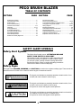
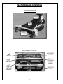
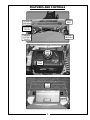
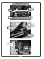
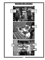
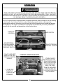
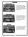
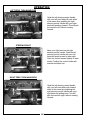
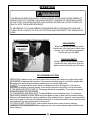
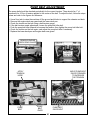
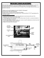
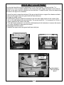
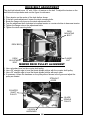
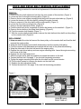
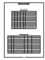
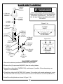
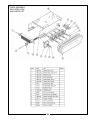
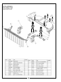
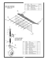
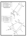
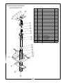
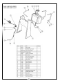
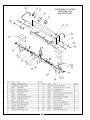
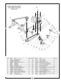
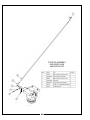
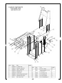
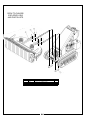
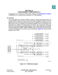
OWNERS MANUAL
MODEL TBB-3000
PART# Q0373
PECO BRUSH BLAZER
TABLE OF CONTENTS
PAGE SECTION
SECTION
Safety Alert Symbols - - - - - General Safety Rules - - - - - Safety Decals - - - - - - - - - - Peco Limited Warranty - - - - Features And Controls - - - - Operation - - - - - - - - - - - - - Pump Adjustment - - - - - - - Pump Belt Adjustment - - - - Drive Belt Idler Adjustment - Drive Belt Adjustment - - - - - Deck Belt Adjustment - - - - - Mower Deck Pulley Alignment
-
-
-
-
-
-
-
-
-
Deck And Drive Belt
Removal And Replacement - - - - - - - - Track Adjustment/Removal/Replacement
Charging The Hydraulic System - - - - - Wiring Diagram - - - - - - - - - - - - - - - - Blade Shaft Assembly - - - - - - - - - - - Label Replacement Part Numbers - - - Regular Maintenance - - - - - - - - - - - - Scheduled Replacement Parts List - - - Hydraulic Oil Specifications - - - - - - - - Exploded Views And Parts Lists - - - - - -
------ 2
------ 3
------ 4
------ 5
- - - - - 6-9
- - - - 10-13
- - - - - - 14
- - - - - - 15
- - - - - - 16
- - - - - - 17
- - - - - - 18
- - - - - - 18
PAGE
-
-
- - - - 19-20
- - - - - - 21
- - - - 22-23
- - - - 24-25
- - - - - - 26
- - - - - - 27
- - - - - - 28
- - - - - - 29
- - - - - - 29
- - - - 30-44
SAFETY ALERT SYMBOLS
Safety Alert Symbol
!
This Safety Alert Symbol means: “ATTENTION! BECOME
ALERT! YOUR SAFETY IS INVOLVED!”
This symbol is used to call attention to safety precautions that
should be followed by the operator to avoid accidents. When
you see this symbol, carefully read the message that follows
and heed its advice. Failure to comply with safety precautions
could result in death or serious bodily injury.
Safety Signs
The signal words DANGER, WARNING, and CAUTION are used on the equipment safety signs. These words are
intended to alert the viewer to the existence and the degree of hazard seriousness.
! DANGER
*This signal word indicates a potentially hazardous situation which, if not
avoided, will result in death or serious injury.
! WARNING
*This signal word indicates a potentially hazardous situation which, if not
avoided, could result in death or serious injury.
*It may also be used to alert against unsafe practices.
! CAUTION
*This signal word indicates a potentially hazardous situation exist which, if
not avoided, will result in minor or moderate injury.
*It may also be used to alert against unsafe practices.
2
GENERAL SAFETY RULES
! WARNING
READ THIS OWNERS MANUAL CAREFULLY BEFORE OPERATING THE
PECO BRUSH BLAZER. DO NOT ALLOW ANYONE WHO IS NOT
FAMILIAR WITH THE SAFETY AND OPERATING INSTRUCTIONS TO
OPERATE THE PECO BRUSH BLAZER. FAILURE TO DO SO MAY
RESULT IN SERIOUS INJURY OR DEATH
?
Read all safety and operating instructions before using the machine.
?
Do not operate the machine near people or animals.
?
Remove any objects that could be thrown by the rotating blades.
?
Always wear eye and ear protection when operating the machine.
?
Keep body parts away from rotating belts and blades.
?
Use caution when operating the machine on slopes. Keep a firm grip on the handle bars.
?
Keep combustibles away from the engine when it is hot.
?
Disengage the blades when crossing roads, sidewalks or gravel drives.
?
Use extra caution when operating in slippery or wet conditions.
?
Do not cut while in reverse or moving backwards. Use extra caution while moving backwards.
?
Do not remove or alter standard parts on the machine. Doing so may result in serious injury and
will void the warranty.
?
Do not operate the machine when excessive noise or vibration is present. Immediately shut off the
engine, disconnect the spark plug wire and allow all moving parts to come to a complete stop.
Inspect for damage, then clean or repair damaged parts if necessary.
?
Do not operate the machine while under the influence of alcohol or medication.
?
Do not operate the machine in poor light conditions. Doing so may result in serious injury.
?
Do not move up and down the face of slopes, always move across the face.
?
Watch for holes, ruts and bumps. Tall grass can hide obstacles.
?
Do not operate the machine on slopes greater than 20 degrees.
?
Do not operate the machine on slopes that are wet or excessively steep.
?
Keep children and pets out of the operating area, and under close adult supervision.
?
Stop the machine immediately if children or pets enter the work area.
?
Never allow children to operate the machine.
?
Use extra caution when approaching shrubs, trees or other objects that may obscure your vision.
?
Never run the engine in an enclosed area without proper ventilation. The exhaust contains carbon
monoxide, which is a colorless, odorless, deadly poisonous gas.
?
Allow the engine to cool down before filling the gas tank.
?
Never make adjustments or repairs while the engine is running.
?
Do not change the engine governor speed. Doing so may result in injury and will void the warranty.
?
No list of warnings and cautions can be all-inclusive. If situations occur that are not covered by
this manual, the operator must apply common sense and operate this machine in a safe manner.
?
WARNING TO PURCHASERS OF INTERNAL COMBUSTION ENGINE EQUIPPED MACHINERY
OR DEVICES IN THE STATE OF CALIFORNIA: The Brush Blazer does not have a spark
arrester muffler. If this machine is to be used on any forest covered or brush covered land in
the state of California, the law requires that a spark arrester must be attached to the exhaust
system and must comply with Section 4442 of the California Public Resources Code.
3
SAFETY DECALS
This label reminds you that flying debris is projected
in the direction of these arrows. Anything or anyone
within this field is in danger of being hit by flying debris.
This label lists safe operation procedures.
This label warns you of the dangers of carbon monoxide.
Do not operate the Brush Blazer without the hoods in place. Keep hands
and other body parts away from rotating belts.
Keep hands and feet clear of the deck edge. Never reach under the mower
deck until the blades have come to a complete stop.
This label reminds you that
other people are in danger
of being hurt by the blades
and flying debris.
4
PECO LIMITED WARRANTY FOR NEW PRODUCTS
A. WHAT IS WARRANTED?
PECO extends the following warranties to the original purchaser of each new PECO consumer product subject
to the following limitations:
1. PRODUCT WARRANTY: Any part of any consumer product, which is defective in material or workmanship as
delivered to the purchaser will be repaired or replaced, as PECO elects, without charge for parts or labor, if the
defect appears within 90 days from the date of delivery of the product to the original purchaser. ALL
DEFECTIVE PARTS MUST BE RETURNED TO PECO FOR INSPECTION TO DETERMINE
VALIDITY OF WARRANTY CLAIMS. Freight and mailing will be borne by the customer.
2. PARTS REPLACED DURING WARRANTY: Any new PECO part which is furnished in performance of this
warranty and is defective in material or workmanship as delivered to the purchaser will be repaired or replaced,
as PECO elects, without charge if the defect appears within 90 days from the date of installation of such part or
before the expiration of the original warranty period, whichever is later.
B. SECURING WARRANTY ADJUSTMENTS.
Call PECO for Return Authorization. Damaged or broken parts, other than engines or batteries, must be
returned to PECO Inc., 100 Airport Road, Arden, NC 28704 before any warranty adjustment can be authorized.
At the time of requesting warranty adjustment, the purchaser must present evidence for date of delivery of the
product. The purchaser shall pay any charge for the product to and from Arden, NC.
C. ITEMS NOT COVERED BY PECO WARRANTY.
Engines and batteries attached to PECO products are covered under a separate warranty by the respective
manufacturer.
D. UNAPPROVED ALTERATION OR MODIFICATION.
All obligations of PECO Inc., under this warranty, shall be terminated if products are altered or modified in ways
not approved by PECO Inc..
E. ACCIDENTS AND NORMAL MAINTENANCE.
The warranty covers only defective material and workmanship. It does not cover depreciation or damage
caused by normal wear, accident, improper use or abuse of products. The cost of normal maintenance and
normal replacement of service items such as belts, cutting blades, hoses, etc., which are not defective shall be
paid for by the purchaser.
F. NO REPRESENTATIONS ADDITIONAL WARRANTIES, DISCLAIMER.
Neither PECO Inc. nor any company affiliated with it makes any warranties, representations or promises as to
the quality of performance of its products other than those set forth herein. Except as described above, PECO
Inc. makes no other warranties AND SPECIFICALLY DISCLAIMS ANY AND ALL IMPLIED
WARRANTIES OF FITNESS AND MERCHANTABILITY.
G. ANY MACHINE USED FOR RENTAL PURPOSES ARE GUARANTEED FOR 45 DAYS FROM DATE
OF ORIGINAL SALE ONLY.
H. REMEDIED EXCLUSIVE.
The only remedies the purchaser has in connection with the breach or performance of any warranty on PECO
Inc. consumer products are set forth above. In no event will PECO be liable for special incidental or
consequential damages.
1. NO SERVICE CENTER WARRANTY.
The selling Service Center makes no warranty on his own on any item warranted by PECO Inc. unless he
delivers to purchaser a separate written warranty certificate specifically warranting the item. The dealer has no
authority to make any representation or promise on behalf of PECO or to modify the terms of this warranty in
any way.
5
FEATURES AND CONTROLS
THE BRUSH BLAZER
ENGINE
HOOD
BELT
HOOD
FRONT
CASTER
INSTRUMENT CLUSTER
AMP
METER
KEY/START
SWITCH
HOUR
METER
RIGHT
STEERING
CONTROL
HANDLE
LEFT
STEERING
CONTROL
HANDLE
THROTTLE
CONTROL
6
FEATURES AND CONTROLS
BLADE
BAR
SPINDLE
HOUSING
CUTTING
TOOTH
CARBIDE
CUTTING
TOOTH
HAMMER
MODULE
TANK
CAP
GAS
TANK
TREE
GATE
DECK
7
FEATURES AND CONTROLS
DRIVE
SPROCKET
FRONT
WHEEL
IDLER
WHEEL
RUBBER
TRACK
HYDRAULIC
OIL TANK CAP
HYDRAULIC
OIL FILTER
HYDRAULIC
OIL TANK
BLADE
ENGAGEMENT
CONTROL
KOHLER
ENGINE
8
FEATURES AND CONTROLS
LEFT
HYDRAULIC
PUMP
BATTERY
RIGHT
HYDRAULIC
PUMP
COUNTER
SHAFT
DECK
BELT
FUEL
RETURN
FUEL
PUMP
FUEL
FILTER
9
OPERATION
! WARNING
READ THE SAFETY AND OPERATION PROCEDURES BEFORE USING THE PECO BRUSH
BLAZER. DO NOT LET ANYONE OPERATE THE PECO BRUSH BLAZER IF THEY HAVE NOT
READ AND ARE FAMILAIR WITH THE SAFETY AND OPERATION PROCEDURES. FAILURE TO
DO SAY MAY RESULT IN SERIOUS INJURY OR DEATH.
The PECO Brush Blazer is equipped with an operator presence switch located on the left steering
control handle. Your left hand must be on the left steering control handle at all times when
operating the machine. Removing your left hand from the left steering control handle will engage
the kill switch on the engine. This featured is designed and installed for your safety. Familiarize
yourself with the controls and descriptions in the section below.
THROTTLE
CONTROL
KEY SWITCH
LEFT STEERING
CONTROL HANDLE
AND OPERATOR
PRESENCE SWITCH
1. PLACE YOUR LEFT
HAND ON THE LEFT
STEERING CONTROL
HANDLE
RIGHT STEERING
CONTROL HANDLE
STARTING THE BRUSH BLAZER
3. TURN THE KEY
SWITCH TO THE
RUN POSITION AND
WAIT FOR THE FUEL
PUMP TO ENGAGE.
ONCE THE FUEL
PUMP IS ENGAGED,
TURN THE KEY TO
THE START POSITION
AND RELEASE
2. PUSH THE
THROTTLE
CONTROL
FORWARD
10
OPERATION
FORWARD MOVEMENT
Grab the front handle bar with your
fingers and the steering control handles
with your thumbs. Push both steering
control handles forward at the same
time to move forward. Push the controls
slightly to move forward slowly. Pushing
harder will increase the speed of your
forward movement.
REVERSE MOVEMENT
Grab the rear handle bar with your
thumbs and the steering control handles
with your fingers. Pull the steering
control handles back, towards you, at
the same time. Pull back slightly to
move slowly in reverse. Pull back
harder to increase the speed of your
reverse movement.
STEERING LEFT
Keep your left hand on the left steering
control handle. Push the right steering
control handle forward to steer to the
left. Push the right steering control
slightly to steer slowly. Pushing the
control harder will execute a sharper
turn.
11
OPERATION
LEFT ZERO TURN MANEUVER
Grab the left steering control handle
with your left hand and pull back while
at the same time grabbing the right
steering control handle with your right
hand and pushing forward. This will spin
the machine left, without mowing
forward.
STEERING RIGHT
Keep your right hand on the right
steering control handle. Grab the left
steering control handle with your left
hand and push forward to steer right.
Push the control forward slightly to steer
slowly. Pushing the control harder will
execute a sharper turn.
RIGHT ZERO TURN MANUEVER
Grab the left steering control handle
with your left hand and push forward
while at the same time grabbing the
right steering control handle with your
right hand and pulling back. This will
spin the machine right, without mowing
forward.
12
OPERATION
! WARNING
THE BRUSH BLAZER CAN EASILY THROW STONES, STICKS AND OTHER DEBRIS AT
GREAT VELOCITY, POSSIBLY CAUSING PROPERTY DAMAGE OR PERSONAL INJURY.
DO NOT RUN THE BRUSH BLAZER OVER GRAVEL DRIVEWAYS, LOOSE STONES OR
MULCH WITH THE BLADES ENGAGED.
IF NECESSARY TO CLEAR DEBRIS FROM MOWER DECK, DISENGAGE THE BLADE,
TURN THE KEY SWITCH TO THE OFF POSITION AND DISCONNECT THE SPARK PLUG
WIRE.
BLADE ENGAGEMENT/DISENGAGEMENT
ENGAGEMENT
PULL UP TO ENGAGE
While holding the left steering control
handle with your right hand, reach down
and pull up on the blade engagement
control with your left hand.
PUSH DOWN TO
DISENGAGE
DISENGAGEMENT
While holding the left steering control
handle with your right hand, push the
blade control down with your left hand.
TIPS ON BRUSH CUTTING
OBSTACLES: Always check your work area before mowing and remove any debris that might
get tangled in or damage the machine. If the mower becomes tangled, turn off the engine and
disconnect the spark plug wire before reaching into the mower deck area.
SLOPES: Do not operate the brush blazer on slopes more than 20 degrees. If you have to
operate the machine on sloping terrain, move across the face of the slope, not up and down.
IF THE MACHINE GETS HUNG UP: Disengage the blade immediately. Try moving in reverse
and backing away from the obstacle.
CUTTING BRUSH AND SAPLINGS: The Brush Blazer can cut saplings up to 4” in diameter.
When cutting saplings or brush, allow the Brush Blazer to ride up and over the material slowly.
Adjust your forward speed to varying conditions. After cutting brush or saplings, you may want to
mow over it again to remove any remaining branches. It its recommended to mow from the trunk
end toward the top as the brush lies on the ground.
CUTTING IN WET CONDITIONS: Use extreme caution when cutting in wet or slippery
conditions. Avoid steep slopes or other slippery areas. Use a lower speed when conditions are
wet or slippery.
13
PUMP ADJUSTMENT
! WARNING
BEFORE ADJUSTING THE PUMPS ON THE BRUSH BLAZER, USE A FLOOR
JACK TO RAISE THE TRACKS OFF OF THE GROUND. USE BLOCKS UNDERNEATH
THE MOWER DECK AND THE REAR CHASSIS TO SUPPORT THE MACHINE.
REVERSE
ADJUSTMENT
BOLT
FRS ROD
JAM NUT
HYDRAULIC
PUMP
JAM NUT
TRAVEL ADJUSTMENT:
1. With the machine securely supported on blocks, loosen the jam nut at the end of one or both
FRS rods to be adjusted.
2. Turn the FRS rods either clockwise or counter clockwise until the tracks do not move when the
machine idles.*
3. After making the necessary adjustments, tighten the jam nut at the end of one or both FRS
rods.
*If the machine travels forward when idling, the FRS rods should be turned clockwise until the
tracks do not move when the machine idles.
*If the machine travels in reverse when idling, the FRS rods should be turned counter-clockwise
until the tracks do not move when the machine idles.
*If the machine pulls to the left when traveling forward, adjust the right FRS rod by turning the rod
clockwise until the track does not move when the machine idles.
*If the machine pulls to the right when traveling forward, adjust the left FRS rod by turning the rod
clockwise until the track does not move when the machine idles.
REVERSE SPEED ADJUSTMENT:
1. With the machine securely supported on blocks, loosen the jam nuts on both reverse
adjustment bolts.
2. Turn the reverse adjustment bolts clockwise to slow the reverse speed or counter-clockwise to
increase the reverse speed.
3. After adjustment, tighten the jam nuts on the reverse adjustment bolts.
! WARNING
DO NOT INCREASE THE REVERSE SPEED FASTER THAN
THE OPERATOR CAN SAFELY WALK BACKWARDS
14
PUMP BELT ADJUSTMENT
The pump belt should be checked periodically for the correct tension. There should be 1” of
movement for 10 lbs. of tension applied to the center of the belt. To adjust the belt, follow the steps
below and refer to the figures for reference:
1. Use a floor jack to raise the machine off the ground and blocks to support the chassis and deck.
2. Remove the engine deck rear guard and the lower deck pan.
3. Check the tension on the belt using a belt tension gauge.
4. If the belt tension needs adjustment, loosen the pump belt idler bolt.
5. Push the pump belt idler forward to increase the tension, then tighten the pump belt idler bolt.
6. Check the tension on the belt again, and adjust the pump belt idler if necessary.
7. Replace the lower deck pan and engine deck rear guard.
REMOVE ENGINE
DECK REAR GUARD
REMOVE
LOWER
DECK PAN
APPLY
TENSION
HERE
PUMP
BELT
MOVE PUMP BELT
IDLER FORWARD
TO INCREASE
THE TENSION
PUMP
BELT
IDLER
PUMP BELT
IDLER BOLT
15
DRIVE BELT IDLER ADJUSTMENT
When the blade engagement control is disengaged, the drive belt idler puts tension on the drive
belt, allowing the drive belt to spin without turning the blades. The drive belt idler must be
checked periodically to ensure that the tension is correct, Follow the steps below and refer to the
figures for reference:
1. Make sure the blade engagement control handle is disengaged.
2. Remove the engine deck rear guard.
3. Place tension on the drive belt as shown in the figure.
4. Measure the gap between the idler and the belt. There should be 1/8”-3/16” gap between the
idler and the belt.
If the idler needs to be adjusted:
1. Remove the cotter pin from the end of the adjustment rod and remove the end of the
adjustment rod from the clutch control crank.
2. Turn the adjustment rod clockwise to move the idler closer to the belt, or counter-clockwise to
move the idler away from the belt.
3. Once the gap between the idler and the belt is correct, insert the adjustment rod into the clutch
control crank and fasten with the cotter pin.
4. Replace the engine deck rear guard.
CLUTCH
CONTROL
CRANK
COTTER
PIN
OFF
DRIVE
BELT
RUN
START
ADJUSTMENT
ROD
ADJUSTMENT
ROD
DRIVE BELT IDLER
FULLY DISENGAGED
DRIVE
BELT
IDLER
BELT
CROSS
SECTION
1/8” TO 3/16”
GAP
16
PLACE
TENSION
HERE
DRIVE BELT ADJUSTMENT
The drive belt should be checked periodically for the correct tension. There should be 1” of
movement for 16 lbs. of tension applied to the center of the belt. Apply the tension to the center of
the belt, on the side of the belt opposite the drive belt idler. To adjust the belt, follow the steps below
and refer to the figures for reference:
1. Use a floor jack to raise the machine off the ground and blocks to support the chassis and deck.
2. Remove the engine deck rear guard and the lower deck pan.
3. Engage the blade control.
4. Use a tension gauge to check the tension on the drive belt. Apply tension to the center of the
belt, on the side opposite the drive belt idler. The correct tension is 1” of movement for 16 lbs. of
tension applied to the center of the belt.
5. If the belt needs adjustment, turn the drive belt adjustment bolt clockwise to increase the tension
or counter-clockwise to decrease the tension.
6. Disengage the blade control.
7. Replace the engine deck rear guard and lower deck pan.
REMOVE ENGINE
DECK REAR GUARD
REMOVE
LOWER
DECK PAN
DRIVE BELT
IDLER
APPLY
TENSION
17
DRIVE BELT
ADJUSTMENT
BOLT
DECK BELT ADJUSTMENT
The deck belt should move 1/2” with 18 lbs. of tension on the belt. To adjust the tension on the
belt follow the steps below and use the figure for reference:
1. Place tension on the center of the deck belt as shown.
2. If the belt needs adjustment, loosen the deck mounting bolts.
3. Break the flange nuts loose on the deck adjustment bolts.
4. Turn the adjustment bolt clockwise to increase tension or counter-clockise to decrease tension.
5. Tighten the flange nuts on the adjustment bolts.
6. Tighten the deck mounting bolts.
PLACE
TENSION
DECK
MOUNTING
BOLT
DECK BELT
DECK
ADJUSTMENT
BOLT
FLANGE
NUT
MOWER DECK PULLEY ALIGNMENT
1. Use a plumbers level on the counter shaft pulley.
2. Use a 30” straight edge to level the blade spindle pulleys with the counter shaft pulley.
3. Use a 30” straight edge to level the blade spindle pulleys with each other.
4. If necessary, loosen the hardware on the pulley sleeve shown in the figure and adjust the
pulley as needed.
STRAIGHT
EDGE
COUNTER
SHAFT
PULLEY
BLADE
SPINDLE
PULLEY
LOOSEN
HARDWARE
18
DECK AND DRIVE BELT REMOVAL/REPLACEMENT
Use the following procedure for removal and replacement of the drive and deck belts:
REMOVAL:
1. Remove the drive belt adjustment bolt from the rear chassis of the machine. (Figure 1)
2. Loosen the two front engine mounting bolts. (Figure 2)
3. Remove the two rear engine mounting bolts along with the main drive take-up. (Figure 2)
4. Loosen the tension on the drive belt by pushing the engine forward.
5. Remove one end of the drive belt from the engine pulley. (Figure 3)
6. Loosen the four deck mounting bolts. (Figure 4)
7. Remove the deck adjustment bolts. (Figure 4)
8. Push the deck back as far as possible to loosen the tension on the deck belt. (Figure 5)
9. Remove the two bolts on the pillow block bearing. (Figure 6)
10. Pivot the counter shaft forward. (Figure 7)
11. With the counter shaft pivoted forward, remove the deck belt and drive belt from the pulleys
on the counter shaft. (Figure 8)
REPLACEMENT:
1. Wrap one end of the drive belt around the lower pulley on the counter shaft and feed the belt
towards the engine pulley.
2. Wrap the deck belt pulley around both blade pulleys and the counter shaft pulley.
3. Pivot the counter shaft backwards and replace the two bolts in the pillow block bearing.
4. Wrap the other end of the drive belt around the engine pulley.
5. Replace the main drive take-up and rear engine mounting bolts. Leave the engine mounting
bolts loose at this time.
6. Replace the drive belt tension bolt.
7. Slide the engine as far back as possible to increase the tension on the belt.
8. Tension the drive belt. See page 17 for drive belt tensioning procedure.
9. Tighten the engine mounting bolts after the drive belt has the correct tension.
10. Pull the deck forward to increase the tension on the deck belt.
11. Replace the deck adjustment bolts.
12. Tension the deck belt. See page 18 for deck belt tensioning procedure.
Figure 1
Figure 2
LOOSEN
BOLTS
REMOVE
BOLTS
REMOVE DRIVE BELT
ADJUSTMENT BOLT
REMOVE MAIN
DRIVE TAKE-UP
19
DECK AND DRIVE BELT REMOVAL AND REPLACEMENT
Figure 4
Figure 3
REMOVE BELT
FROM PULLEY
LOOSEN
DECK
MOUNTING
BOLTS
REMOVE
ADJUSTMENT
BOLTS
Figure 5
Figure 6
PUSH DECK
BACK AS FAR
AS POSSIBLE
Figure 7
REMOVE
HARDWARE
Figure 8
PIVOT THE
COUNTER SHAFT
FORWARD
REMOVE
DECK BELT
REMOVE
DRIVE BELT
20
TRACK ADJUSTMENT/REMOVAL/REPLACEMNT
REMOVAL:
1. Remove the tension from the front wheel by turning the tension bolt clockwise. The tension bolt
is located behind the front wheel.
2. Remove the three bolts from the sprocket hub and pull the sprocket towards you.
3. Once the sprocket is loose from the hub, use a pry bar to pivot the sprocket forward, resting in
between the two rear idler wheels.
4. With the front wheel and the sprocket loose, the track can be removed.
REPLACEMENT:
1. With the front wheel and sprocket loose, place the track onto the wheel assembly.
2. Align the sprocket teeth with the center grooves on the track.
3. Rotate the sprocket from in between the rear idler wheels and align the sprocket mounting
bolts with the holes on the sprocket hub.
4. Tighten the sprocket mounting bolts.
5. Tighten the track tension with the tension bolt.
ADJUSTMENT:
1. When adjusting the tension of the tracks, you will need 170 lbs. of weight resting on the center
of the track. Someone approximately 170 lbs. can stand on the track, if necessary.
2. Use a scale to measure the distance the track moves once the weight is applied.
3. There should be 1-1/2” of movement in the track after the weight is applied.
4. Turn the tension bolt clockwise to decrease tension, or counter-clockwise to increase tension.
MOUNTING
BOLTS
FRONT
WHEEL
SPROCKET
TENSION
BOLT
REAR
IDLER
WHEELS
TRACK
PLACE WEIGHT
IN THE CENTER
OF THE TRACK
CORRECT TENSION:
1-1/2” OF MOVEMENT
21
CHARGING THE HYDRAULIC SYSTEM
! DANGER
DO NOT EXCEED MORE THAN 10 POUNDS OF PRESSURE WHEN
CHARGING THE HYDRAULIC SYSTEM. FAILURE TO DO SO MAY
RESULT IN SYSTEM FAILURE AND/OR PERSONAL INJURY.
CONTACT YOUR BRUSH BLAZER DEALER FOR THE HYDRAULIC CHARGING KIT
ORDERING INFORMATION:
?
HYDRAULIC CHARGING KIT (PART#: TBB2-0068) INCLUDES:
(1) 1/4” AIR REGULATOR WITH GAUGE (PART#: TBB2-0067)
(1) 1/4” FEMALE COUPLER (PART#: TBB2-0066)
(1) 1/4” MALE PLUG (PART#: TBB2-0063)
(1) HYDRAULIC OIL TANK CAP WITH FITTING (PART#: TBB2-0065) INCLUDES:
(1) HYDRAULIC OIL TANK CAP DRILLED FOR 1/4” NPT (PART#: TBB2-0064)
(1) 1/4” MALE PLUG (PART#: TBB2-0063)
TOOLS REQUIRED:
(1) AIR COMPRESSOR
(1) AIR HOSE WITH 1/4” FEMALE COUPLER
(1) CONTAINER FOR COLLECTING FLUID
(1) HYDRAULIC CHARGING KIT
PROCEDURE:
1. Loosen, but do not remove the charge relief valve on both hydraulic pumps. Figure 1
2. Disconnect the return line. Attach a hose to the end of the return line and use a suitable
container to collect any fluid leakage that may occur. Figure 2
LOOSEN THE
CHARGE
RELIEF VALVE
DISCONNECT RETURN
LINE AND ATTACH HOSE
TO CONTAINER
FIGURE 1
FIGURE 2
22
CHARGING THE HYDRAULIC SYSTEM
3. Attach the air regulator to the hydraulic oil tank cap with fitting and to the air hose. See Figure 3.
Make sure the air regulator is in the off position. Figure 4
4. Turn the air compressor on and dial in 7 pounds on the air regulator gauge. Do not exceed
more than 10 pounds of pressure, doing so may result in system failure and/or personal injury.
5. With the air regulator attached to the hydraulic oil tank cap, carefully screw the tank cap onto
the hydraulic tank. Figure 5
6. Watch the return line for hydraulic oil. When the oils flows through the return line, the hydraulic
system has been charged. Figure 6
7. Tighten the charge relief valves on both pumps.
8. Remove the hydraulic charging kit and replace the hydraulic oil tank cap.
AIR
HOSE
FEMALE
COUPLER
Figure 3
HYDRAULIC OIL
TANK CAP WITH
FITTING
PRESSURE GAUGE
REGULATOR IN THE
OFF POSITION
AIR REGULATOR
WITH GAUGE
Figure 4
CAREFULLY SCREW
THE TANK CAP ONTO
THE HYDRAULIC TANK
WATCH THE
RETURN LINE FOR
HYDRAULIC FLUID
Figure 6
Figure 5
23
SEE PAGE 25 FOR WIRE LOCATION
AND WIRE CONNECTION TABLE
WIRING DIAGRAM
24
WIRING DIAGRAM
WIRE LOCATIONS
WIRE#
PART#
COLOR
LENGTH GAGE
CONNECTION
1A-1B
P0166
BLACK
40"
6
BATTERY TO GROUND
2A-2B
P0167
RED
50"
6
BATTERY TO STARTER
3A-3B
P0168
RED
46"
10
BATTERY TO AMP METER
4A-4B
P0169
BLACK
40"
14
STARTER TO STARTER SWITCH
5A-5B
P0170
ORANGE
40"
14
STARTER TO STARTER SWITCH
6A-6B
P0171
GREEN
38"
14
STARTER TO STARTER SWITCH
7A-7B
P0172
RED
32"
18
KOHLER HARNESS TO LED NEG.
8A-8B
P0173
GREEN
30"
14
KOHLER HARNESS TO AMP METER
9A-9B
P0174
WHITE
32"
18
KOHLER HARNESS TO LED POS.
10A-10B
P0175
ORANGE
14"
14
KOHLER HARNESS TO FUEL PUMP
11A-11B
P0176
YELLOW
30"
14
KOHLER KILL SWITCH TO WIRE 13
12A-12B
P0177
BLACK
20"
14
KILL SWITCH TO GROUND
13A-13B
P0178
WHITE
20"
14
KILL SWITCH TO WIRE 11
14A-14B
P0179
BLACK
4"
14
FUEL PUMP TO GROUND
15A-15B
P0180
BLACK
30"
14
HOUR METER TO SPARK PLUG
WIRE CONNECTIONS
WIRE END PART#
DESCRIPTION
WIRE END
PART#
DESCRIPTION
1A
P0091
6 GAGE RING TERMINAL 5/16"
8B
P0109
16-14 RING TERMINAL #10
1B
P0091
6 GAGE RING TERMINAL 5/16"
9A
P0109
16-14 FEMALE TERMINAL
2A
P0091
6 GAGE RING TERMINAL 5/16"
9B
P0106
16-14 FEMALE PUSH ON
2B
P0091
6 GAGE RING TERMINAL 5/16"
10A
P0109
16-14 FEMALE TERMINAL
3A
P0092
12-10 GAGE RING TERMINAL 5/16"
10B
P0165
16-14 RING TERMINAL #6
3B
P0093
12-10 GAGE RING TERMINAL #10
11A
P0111
16-14 MALE DISCONNECT
4A
P0098
16-14 GAGE RING TERMINAL 5/16"
11B
P0099
16-14 MALE PUSH ON
4B
P0109
16-14 FEMALE TERMINAL
12A
P0098
16-14 RING TERMINAL 5/16"
5A
P0106
16-14 FEMALE PUSH ON
12B
P0107
16-14 RING TERMINAL #10
5B
P0109
16-14 FEMALE TERMINAL
13A
P0099
16-14 MALE PUSH ON
6A
P0098
16-14 GAGE RING TERMINAL 5/16"
13B
P0107
16-14 RING TERMINAL #10
6B
P0109
16-14 FEMALE TERMINAL
14A
P0098
16-14 RING TERMINAL 5/16"
7A
P0109
16-14 FEMALE TERMINAL
14B
P0113
16-14 FORK TERMINAL
7B
P0106
16-14 FEMALE PUSH ON
15A
******
NO TERMINAL
8A
P0109
16-14 FEMALE TERMINAL
15B
P0106
16-14 FEMALE PUSH ON
25
BLADE SHAFT ASSEMBLY
(1) N0152
UPPER
BEARING
! WARNING
STOP THE ENGINE, REMOVE BATTERY
CABLE AND SUPPORT THE DECK BEFORE
WORKING UNDERNEATH. FAILURE TO
DO SO MAY RESULT IN SERIOUS INJURY
OR DEATH.
(1) TBB-0023
SPINDLE
HOUSING
(1) N0153
LOWER
BEARING
(1) J0259
OIL SEAL
Figure 2-1a
(1) TBB-0197
SHAFT
ASSEMBLY
CUTTING
BLADE
(1) TBB-0135
BLADE BAR
(5) K1247
1/2”-20
LOCK NUT
SHARPEN AT
45 DEGREES
(2) K0302
3/4”-10
LOCK NUT
(2) TBB-0137
HAMMER
MODULE
Figure 2-1b
ROTATION
DIRECTION
(2) TBB-0178
PIVOT
WASHER
(4) TBB-0190
CUTTING
BLADE
(2) TBB-0165
CUTTING
TOOTH
(2) TBB-0163
PIVOT
BUSHING
(2) K0298
3/4”-10 x 2-1/4”
SHCS
ROTATION
DIRECTION
(8) K0297
3/8”-16 x 3/4”
SHCS
BLADE REPLACEMENT
1. Secure the deck and position the blades for easy access.
2. Remove the (8) cap screws P#(K0297) from the cutting blades.
3. Inspect the cutting blade P#(TBB-0190), and sharpen if possible. When sharpening, use
Figure 2-1a for reference.
4. Check the cutting tooth P#(TBB-0165) for wear. If the cutting tooth needs replacement, mount
the new tooth 5/8” from the tip of the tooth to the face of the hammer module P#(TBB-0137).
5. Install the cutting blades as shown in Figure 2-1b.
26
LABEL REPLACEMENT PART NUMBERS
R2002
R1040
R1093
R1099
R1047
R2000
R2004
R2005
R1045
R1044
R1091
R1098
R2001
R2003
27
REGULAR MAINTENANCE
BATTERY REPLACEMENT:
1. Remove the deck and engine hood.
2 Disconnect the negative (-) battery cable.
3. Disconnect the positive (+) battery cable.
4. Remove the battery hold down clamp.
5. Remove the battery.
6. Clean the terminals and cable ends.
7. Install the new battery and replace battery hold down clamp.
8. Connect the positive (+) battery cable.
9. Connect the negative (-) battery cable.
10. Replace the deck and engine hood.
ELECTRICAL SYSTEM SERVICE:
1. Make sure the battery cables and terminals are clean and fastened tightly.
2. Check the electrolyte level in the battery often.
3. Remove any build-up or corrosion on the battery with a baking soda and water solution.
4. Cover the battery terminals with grease to prevent corrosion.
5. Check all electrical wires for loose connections.
AIR CLEANER SERVICE:
1. Remove the deck and engine hood.
2. Remove the outer air filter cover.
3. Remove the wing nut and inner air filter cover.
4. Remove the pre-cleaner from the filter and clean with warm water and detergent.
5. Squeeze dry the pre-cleaner and add one tablespoon of SAE 30 oil evenly to the pre-cleaner. 6.
Work the oil into the pre-cleaner and wring out the excess oil.
7. Replace the pre-cleaner onto the inner air filter cover.
8. Replace the inner air filter cover and wing nut.
9. Replace the outer air filter cover, deck and engine hood.
ELEMENT REPLACEMENT:
1. Remove the deck and engine hood.
2. Remove the outer air filter cover.
3. Remove the wing nut and inner air filter cover.
4. Replace the filter element.
5. Replace the inner air filter cover and wing nut.
6. Replace the outer air filter cover deck and engine hood.
END OF SEASON STORAGE
?
Change the oil and oil filter.
?
Clean and replace the pre-cleaner filter.
?
Clean any dirt and debris from the muffler area of the engine.
?
If storing longer than 30 days, use a gas stabilizer.
?
Close the fuel shut-off valve.
?
Remove any grass, weeds or brush from the blade and deck area.
?
Store the battery in a dry area that will not freeze.
?
Remove and sharpen or replace blades as necessary.
ENGINE SERVICE: Refer to the Kohler 26HP service manual for instructions.
28
SCHEDULED REPLACEMENT PARTS LIST
PLEASE NOTE: These are only recommended replacement times. The replacement times on the
parts in this list will vary depending on the work environment and operating habits.
DESCRIPTION
BANDED KEVLAR DECK BELT
B SECTION KEVLAR PUMP BELT
BANDED KEVLAR DRIVE BELT
CUTTING BLADES
CUTTING TEETH
CUTTING BLADE SHCS
(3/8”-16 x 3/4”)
HAMMER MODULE
HAMMER MODULE PIVOT BUSHING
HAMMER MODULE WASHER
HAMMER MODULE SHCS
(3/4”-10 x 2-1/4”)
HAMMER MODULE NYLOC NUT
(3/4”-10)
BLADE BAR
BLADE BAR NYLOC NUT
(1/2”-13)
ZINGA HYDRO OIL FILTER
KOHLER ENGINE OIL FILTER
(KOHLER# 1205001)
IGNITION SPARK PLUG
(KOHLER# 1213202 RC12YC)
KOHLER PRE-CLEANER ELEMENT
(KOHLER# 2408305)
KOHLER AIR CLEANER ELEMENT
(KOHLER# 2408303)
KOHLER FUEL FILTER
(KOHLER# 25 050 10S)
PART #
HOURS
REQUIRED
M0232
M0260
M0233
TBB-0190
TBB-0165
K0297
400
500
300
016
004
025
01
01
01
08
04
16
TBB-0137
TBB-0163
TBB-0178
K0298
300
300
300
300
04
04
04
04
K0302
300
04
TBB-0135
K1247
600
600
02
10
U0030
TBB-0239
050
200
01
01
TBB-0236
200
01
TBB-0238
025
01
TBB-0237
100
01
TBB-0243
200
01
HYDRAULIC OIL
When replacing hydraulic fluid, the following grades and levels are approved for the Brush Blazer:
Mobil 1 Synthetic 5W-30, 10W-30, 15W-50
Amoco Ultimate 10W-40
Shell Gemini 10W-40, 15W-50
Helix Ultra 5W-40, 10W-40
Mobil Super HP 10W-40, 20W-50
Viscosity Oil 10W-40
Aero Shell 15W-50
The Brush Blazer comes equipped with Aero Shell 15W-50
29
HYDRAULIC SYSTEM
EXPLODED VIEW AND
PARTS LIST
30
TRACK ASSEMBLY
EXPLODED VIEW
AND PARTS LIST
31
DECK ASSEMBLY
EXPLODED VIEW
AND PARTS LIST
32
TREE GATE ASSEMBLY
EXPLODED VIEW AND
PARTS LIST
CASTER ASSEMBLY
EXPLODED VIEW
AND PARTS LIST
33
ENGINE HOOD EXPLODED
VIEW AND PARTS LIST
BELT HOOD EXPLODED
VIEW AND PARTS LIST
34
COUNTER SHAFT EXPLODED
VIEW AND PARTS LIST
35
Item#
Part#
Title
Quantity
1
TBB-0250
C. SHAFT ASSY.
1
2
N0149
C. SHAFT PILLOW BEARING
1
3
TBB-0247
C. SHAFT
1
4
S0160
C. SHAFT SHEAVE BUSHING
1
5
TBB-0161
DECK SHEAVE
1
6
TBB-0021
BEARING SPACER BLOCK
1
7
TBB-0162
C. SHAFT DRIVE SHEAVE
1
8
S0187
C. SHAFT DRIVE SHEAVE BUSHING 1
9
TBB-0233
LWR. C. SHAFT MNT.
10
N0150
FAFNIR FLANGE CARTRIDGE RCJ 1 1
11
S0179
LRG. C. SHAFT SPACER
1
12
S0173
SML. C. SHAFT SPACER
1
13
TBB-0267
BELT RETAINER DISC
1
14
J0240
DRAW LATCH
2
15
K1154
5/16"-18 x 1" HHCS
9
16
K1236
1/2"-13 x 3" HHCS
2
17
K0400
1/2" SAE FLAT WASHER ZINC
2
18
K1247
1/2"-13 NYLOC NUT
2
19
K1064
10-24 x 1/2" PSLMS
4
20
K1068
10-24 NYLOC NUT
4
21
K0328
7/16"-14 x 1-1/4" HHCS
4
22
K0053
7/16" LOCK WASHER
4
23
K0329
7/16"-14 x 2" HHCS
4
24
K0043
5/16" LOCK WASHER
3
1
FUEL LINE EXPLODED
VIEW AND PARTS LIST
36
TOWER EXPLODED VIEW
AND PARTS LIST
37
INSTRUMENT CLUSTER
EXPLODED VIEW
AND PARTS LIST
38
DECK AND DRIVE BELT
EXPLODED VIEW AND
PARTS LIST
39
FRS ROD ASSEMBLY
EXPLODED VIEW
AND PARTS LIST
40
CHASSIS COMPONENTS
EXPLODED VIEW
AND PARTS LIST
41
HYDRAULIC COMPONENTS
EXPLODED VIEW
AND PARTS LIST
42
BATTERY AND MUFFLER GUARD
EXPLODED VIEW AND PARTS LIST
43
DECK TO CHASSIS
EXPLODED VIEW
AND PARTS LISTS
Item#
1
2
3
4
Part#
TBB2-0018
K1036
K1247
K0055
Title
DECK MNTG. PLATE ASSY.
1/2"-13 x 3" ALL THREAD HHCS
1/2"-13 NYLOC NUT
1/2" FLAT WASHER 1.383 OD x .560 ID x .120 T
44
Quantity
2
2
6
4
NOTES
P.O. BOX 1197
ARDEN, NORTH CAROLINA 28704
(800) 438-5823 OR (828) 684-1234 FAX: (828) 684-0858
EMAIL: [email protected]
WEBSITE: www.lawnvac.com