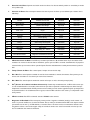
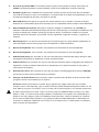
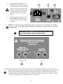
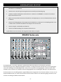
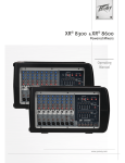
1
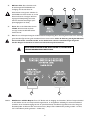
XR®600G Operation Manual
For more information on other great Peavey products, go to your local Peavey dealer or online at www.peavey.com
Intended to alert the user to the presence of uninsulated “dangerous voltage” within the product’s
enclosure that may be of sufficient magnitude to constitute a risk of electric shock to persons.
Intended to alert the user of the presence of important operating and maintenance (servicing)
instructions in the literature accompanying the product.
CAUTION: Risk of electrical shock — DO NOT OPEN!
CAUTION: To reduce the risk of electric shock, do not remove cover. No user serviceable parts inside.
Refer servicing to qualified service personnel.
WARNING: To prevent electrical shock or fire hazard, do not expose this appliance to rain or moisture.
Before using this appliance, read the operating guide for further warnings.
Este símbolo tiene el propósito, de alertar al usuario de la presencia de “(voltaje) peligroso” sin
aislamiento dentro de la caja del producto y que puede tener una magnitud suficiente como para
constituir riesgo de descarga eléctrica.
Este símbolo tiene el propósito de alertar al usario de la presencia de instruccones importantes sobre la
operación y mantenimiento en la información que viene con el producto.
PRECAUCION: Riesgo de descarga eléctrica ¡NO ABRIR!
PRECAUCION: Para disminuír el riesgo de descarga eléctrica, no abra la cubierta. No hay piezas útiles
dentro. Deje todo mantenimiento en manos del personal técnico cualificado.
ADVERTENCIA: Para evitar descargas eléctricas o peligro de incendio, no deje expuesto a la lluvia o
humedad este aparato Antes de usar este aparato, Iea más advertencias en la guía de operación.
Ce symbole est utilisé dans ce manuel pour indiquer à l’utilisateur la présence d’une tension dangereuse
pouvant être d’amplitude suffisante pour constituer un risque de choc électrique.
Ce symbole est utilisé dans ce manuel pour indiquer à l’utilisateur qu’il ou qu’elle trouvera d’importantes
instructions concernant l’utilisation et l’entretien de l’appareil dans le paragraphe signalé.
ATTENTION: Risques de choc électrique — NE PAS OUVRIR!
ATTENTION: Afin de réduire le risque de choc électrique, ne pas enlever le couvercle. Il ne se trouve à
l’intérieur aucune pièce pouvant être reparée par l’utilisateur. Confiez I’entretien et la réparation de
l’appareil à un réparateur Peavey agréé.
AVERTISSEMENT: Afin de prévenir les risques de décharge électrique ou de feu, n’exposez pas cet
appareil à la pluie ou à l’humidité. Avant d’utiliser cet appareil, lisez attentivement les avertissements
supplémentaires de ce manuel.
Dieses Symbol soll den Anwender vor unisolierten gefährlichen Spannungen innerhalb des Gehäuses
warnen, die von Ausreichender Stärke sind, um einen elektrischen Schlag verursachen zu können.
Dieses Symbol soll den Benutzer auf wichtige Instruktionen in der Bedienungsanleitung aufmerksam
machen, die Handhabung und Wartung des Produkts betreffen.
VORSICHT: Risiko — Elektrischer Schlag! Nicht öffnen!
VORSICHT: Um das Risiko eines elektrischen Schlages zu vermeiden, nicht die Abdeckung enfernen. Es
befinden sich keine Teile darin, die vom Anwender repariert werden könnten. Reparaturen nur von
qualifiziertem Fachpersonal durchführen lassen.
ACHTUNG: Um einen elektrischen Schlag oder Feuergefahr zu vermeiden, sollte dieses Gerät nicht dem
Regen oder Feuchtigkeit ausgesetzt werden. Vor Inbetriebnahme unbedingt die Bedienungsanleitung lesen.
2
IMPORTANT SAFETY INSTRUCTIONS
WARNING: When using electrical products, basic cautions should always be followed, including the following:
1.
2.
3.
4.
5.
6.
7.
8.
9.
10.
11.
12.
13.
14.
15.
16.
17.
18.
Read these instructions.
Keep these instructions.
Heed all warnings.
Follow all instructions.
Do not use this apparatus near water.
Clean only with a dry cloth.
Do not block any of the ventilation openings. Install in accordance with manufacturer’s instructions.
Do not install near any heat sources such as radiators, heat registers, stoves or other apparatus (including
amplifiers) that produce heat.
Do not defeat the safety purpose of the polarized or grounding-type plug. A polarized plug has two blades with one
wider than the other. A grounding type plug has two blades and a third grounding plug. The wide blade or third
prong is provided for your safety. If the provided plug does not fit into your outlet, consult an electrician for
replacement of the obsolete outlet.
Protect the power cord from being walked on or pinched, particularly at plugs, convenience receptacles, and the
point they exit from the apparatus.
Note for UK only: If the colors of the wires in the mains lead of this unit do not correspond with the terminals in your
plug‚ proceed as follows:
a) The wire that is colored green and yellow must be connected to the terminal that is marked by the letter E‚ the
earth symbol‚ colored green or colored green and yellow.
b) The wire that is colored blue must be connected to the terminal that is marked with the letter N or the color black.
c) The wire that is colored brown must be connected to the terminal that is marked with the letter L or the color red.
Only use attachments/accessories provided by the manufacturer.
Use only with a cart, stand, tripod, bracket, or table specified by the manufacturer, or sold with the apparatus. When
a cart is used, use caution when moving the cart/apparatus combination to avoid injury from tip-over.
Unplug this apparatus during lightning storms or when unused for long periods of time.
Refer all servicing to qualified service personnel. Servicing is required when the apparatus has been damaged in
any way, such as power-supply cord or plug is damaged, liquid has been spilled or objects have fallen into the
apparatus, the apparatus has been exposed to rain or moisture, does not operate normally, or has been dropped.
Never break off the ground pin. Write for our free booklet “Shock Hazard and Grounding.” Connect only to a power
supply of the type marked on the unit adjacent to the power supply cord.
If this product is to be mounted in an equipment rack, rear support should be provided.
Exposure to extremely high noise levels may cause a permanent hearing loss. Individuals vary considerably in
susceptibility to noise-induced hearing loss, but nearly everyone will lose some hearing if exposed to sufficiently
intense noise for a sufficient time. The U.S. Government’s Occupational and Health Administration (OSHA) has
specified the following permissible noise level exposures:
Duration Per Day In Hours
8
6
4
3
2
1 1⁄2
1
1
⁄2
1
⁄4 or less
Sound Level dBA, Slow Response
90
92
95
97
100
102
105
110
115
According to OSHA, any exposure in excess of the above permissible limits could result in some hearing loss. Ear plugs or protectors to the
ear canals or over the ears must be worn when operating this amplification system in order to prevent a permanent hearing loss, if exposure
is in excess of the limits as set forth above. To ensure against potentially dangerous exposure to high sound pressure levels, it is
recommended that all persons exposed to equipment capable of producing high sound pressure levels such as this amplification system be
protected by hearing protectors while this unit is in operation.
SAVE THESE INSTRUCTIONS!
3
ENGLISH
®
XR 600G Powered Mixers
Thank you for purchasing the XR600G by Peavey. This powered mixer includes many of the latest technological developments from
Peavey engineers. Incorporating two‚ 200 Watt amplifiers‚ dual 9-band EQ‚ digital effects‚ FLS® (Peavey’s award-winning Feedback
Locating System)‚ DDT™ speaker protection as well as many other features‚ this compact‚ lightweight powered mixer is perfect for
most any application. More power. More features. More reliability. All from Peavey!
Please read this guide carefully to ensure your personal safety as well as the safety of your equipment.
Features
◆
6 low-noise‚ low-Z mic preamps
◆
7 line inputs
◆
3-band equalization each channel
◆
monitor sends on each channel
◆
effects send: channels 1–6
◆
25 dB pad: channels 1–4
◆
switchable 9-band EQ‚ assignable to monitor or channel 1 with FLS™
◆
dual main or main/monitor power amp mode switch
◆
dedicated 9-band EQ for mains with FLS™
◆
DSP-based effects; 16 presets with parameter control
◆
signal/clipping indicator on each channel
◆
48 Volt phantom power
◆
dual 200 Watts per channel internal power amplifiers
◆
DDT speaker protection with activity LED
◆
mute switch for input channels 1–6
4
QUICK SET-UP GUIDE
1.
Connect speakers to your XR600G. Route speaker cable for safety‚ taping down if necessary.
2.
Be certain that all levels are down and your EQ is flat.
3.
Connect all microphones and instruments. Turn on power to the XR600G and set master controls to the 12:00
position.
4.
Use mode switch to select both power amplifiers for main speakers or one amplifier for mains and one amplifier for
monitors.
5.
Adjust channel level controls for proper volume mix. Engage pad switches if a channel distorts or if the channel
becomes loud very quickly as its control is turned up.
6.
Adjust graphic and channel EQ as needed.
7.
Set and adjust the effects settings and channel send.
8.
Now‚ play like you’ve never played before. Have fun!
XR 600G Front Panel
The standard channels (1–6) feature discrete‚ low-noise mic preamps with globally-switched phantom power and a 3-band EQ.
Channels 1–4 offer balanced 1/4" line-level inputs and feature a full 25 dB pad switch to accommodate a wide range of input signals.
Finally‚ channels (5–7) have dual input jacks (summed) for your tape‚ CD or synth input.
The master section features a DSP-based digital effects processor. This processor includes 16 presets‚ that provide a selection of
effects designed to enhance your sound. There is also a parameter control that allows you to set the Time/Size of the effect.
5
Channel Section
Channels 1–4 feature all of the same great controls. Channels 5 and 6 include all of the
features of the first four channels except the -25 dB pad. These two channels also feature
dual 1/4" input jacks (summed to mono); perfect for digital keyboards or other devices with
stereo outputs. Channel 7 is designed primarily for tape players/recorders‚ CD players or
other similar devices.
9
Channels 1–4
8
1.
Mic Input: XLR balanced‚ low-impedance channel input optimized for a
microphone or other low-impedance source. Pin 2 is the positive input. Due to the
wide range of gain adjustment‚ signal levels as high as +10 dBV (2.45 V RMS) can be
accommodated with the pad switch engaged. When the phantom power is enabled‚
this connector has +48 V on pins 2 and 3 with pin 1 as the ground reference.
2.
Line Input: 1/4" balanced TRS inputs. The tip is the positive input which may also
be used for unbalanced inputs. A pad switch is provided to attenuate strong
signals present at this input. Note: The Mic input and the Line input cannot be used
simultaneously within the same channel.
3.
Pad: Attenuates the input signal by -25 dB. If you notice distortion from a
particular channel or if the channel becomes loud very quickly‚ try engaging this
switch. In addition to increasing the dynamic range‚ the channel input can now
accommodate a higher input level before clipping occurs. This may be necessary
when close-mic’ing a loud guitar amp or drum kit.
7
6
5
4.
Level & Signal/Clipping Indicator: Sets the signal level sent to the main mix.
The bi-color LED is green when signal is present and red when clipping occurs. If
clipping occurs‚ turn the channel Level control (4) down. If the channel clips when
turning the Level control up only slightly‚ try engaging the Pad switch (3).
5.
Mon (monitor): Controls the level of each channel signal (pre-EQ) that is added
to the monitor mix.
6.
Low EQ: A shelving type of active tone control that varies the bass frequency
levels (±15 dB at 70 Hz). This will add depth to thin-sounding signals or clean up
muddy ones. As with any EQ‚ use sparingly. Too much of this EQ can give you a
booming bottom end.
4
3
2
1
7.
Mid EQ: A band pass (peak/notch) type of active tone control that varies the
mid-range frequencies (±15 dB at 1 kHz).
8.
High EQ: A shelving type of active tone control that varies the treble frequency (±15 dB at 12 kHz). This control is
designed to remove noise or add brilliance to the signal depending on the quality of the source.
9.
Efx: This control varies the level into the digital effects processor bus‚ adjusting signal level from the individual channel to
the digital processor. It is post gain and will be affected by the gain control.
6
Channels 5–6
10 & 11.
Line Inputs: High impedance 1/4" input for line-level signals. The inputs are summed
to mono‚ allowing a stereo source to be input into these channels. In critical
situations‚ two mono line sources can be connected to one input.
11
10
Channel 7
12.
Line In: This pair of RCA phono jacks accepts a stereo input (nominally
-10 dBV) from the output of a tape deck‚ CD player or other similar device.
The signal is placed on the main channel as well as the monitor mix.
13.
Line Out: This pair of RCA phono jacks provides a signal for the recording
inputs of a stereo tape‚ CD player or other similar device.
CAUTION: DO NOT HOOK THE LINE IN AND LINE OUT TO THE
INPUTS AND OUTPUTS OF THE SAME DEVICE. DOING SO WILL
FORM A LOOP THAT CAN CAUSE SEVERE FEEDBACK. USE
SEPARATE DECKS FOR RECORDING AND PLAYBACK.
14
14.
Mute Channels 1–6: What a great feature! Take a break‚ mute channels 1–6
without changing the mic level settings. Use channel 7 for your break music.
Just remember to unmute before beginning your performance.
13
12
7
Master Section
You’ll find enough features in the Master Section of the XR600G to fit most sound reinforcement situations. Our audacious
engineers (these guys are nuts) have been busy adding features to these products that you won’t find in any other powered mixer.
A DSP effects processor‚ 9-band EQ‚ FLS® Feedback Locating System‚ DDT™ speaker protection and much more.
15
16
17
18
19
20
22
21
23
24
26
27
25
28
34
33
32
31
30
8
29
15.
EFX Defeat: Depressing this button defeats the Effects. The effects may also be defeated via the footswitch input (32).
16.
EFX Select: This rotary switch selects one of sixteen available effects. See the table below.
Effect
Description
Application
Parameter
1
Hall Rev
Medium Concert Hall
Ensemble
Rev Time
2
Large Hall Rev
Larger Concert Hall Darker
Gen Reverb
Rev Time
3
Room 1 Rev
Intimate Room Bright
Pop Vocal
Rev Time
4
Room 2 Rev
Larger Room Darker
Drums,Rhythm
Rev Time
5
Plate 1 Rev
Bright
Pop Vocal
Rev Time
6
Plate 2 Rev
Darker
Drums
Rev Time
7
Cathedral
Large Space, Long and Darker
Choir
Rev Time
8
Spring
Classic Spring
Guitar
Rev Time
9
Delay 1
Single Delay (Slap-back)
Voc/Instr
Dly Time
10
Delay 2
Warm Delay with Repeats
Instruments
Dly Time
11
Delay 3
Dark Delay with Repeats
Instruments
Dly Time
12
Tape Delay
Warm Delay
Instruments
Dly Time/Feedback
13
Doubler
Single Delay, 30 - 120 ms
Instruments
Dly Time
14
Shimmer
Warm Delay with Modulation
Instruments
Dly Time
15
Vocal Enhancement 1
Brightens and adds Room Reverb
Vocals
Rev Level
16
Vocal Enhancement 2
Brightens and adds Spring Reverb
Vocals
Rev Level
17.
Effects Input CLip LED: This red LED illuminates to indicate 6 dB of headroom before the signals being sent to the
effects circuit are clipped. Ideally‚ you want this LED to light only occasionally. An occasional blink indicates that your
levels are set optimally. Listen carefully to the output to determine the final setting.
18.
EFX Time: This control adjusts the time of the particular reverb or delay.
19.
EFX to Monitor: This control adjusts the amount of effects signal sent to the monitor mix. This allows effects to be
heard from the stage via the monitors. Keep this control as low as possible.
20.
EFX to Main: Adjusts the amount of effects sent to the main mix. Controls the amount of effects sent to the front-ofhouse mix. ✓ Remember: A little goes a long way!
21.
FLS® Feedback Locating System: When feedback occurs‚ the corresponding LED of the frequency band that is
feeding back will illuminate over the slider to be adjusted. Slowly bring the corresponding slider down until the feedback
is gone. The LED will remain illuminated for a few seconds after the feedback is gone. If the feedback doesn't return‚ all
the LEDs will become active again acting as a normal EQ.
22.
Power LED: This LED illuminates when power is supplied to the XR600G.
23.
EQ Assignment: This switch allows you to patch the second (top) EQ to either the Monitor or to Channel 1. The
default position is the Monitor mode. This is indicated by the illuminated green LED. Push the button to change this to
the Channel 1 mode and the yellow LED lights. This is a great feature to use if you have a critical instrument such as an
acoustic guitar or a lead vocal. You can assign the top 9-band EQ to this channel! Although‚ keep in mind that this
eliminates the EQ for your monitors.
9
24.
DDT™ Speaker Protection: Peavey’s award-winning speaker protection is built into the XR600G. This important
feature allows you to maximize the power amplifiers without fear of distortion.
25.
Graphic EQ: These 9-band EQs are fixed on one-octave centers. They are designed for 12 dB of cut or boost. The
equalizers are placed before the Preamp outputs and therefore‚ the Main and monitor preamp outputs are post-EQ.
26.
Monitor Level: This control sets the overall level of the monitor signal that is sent to the Monitor output jack. This
control also sets the monitor level going to the power amp when in Main/Mono mode.
27.
Power Amp Mode: This button is used to configure the XR600G power amps as either main/main or main/monitor. It is
recessed to prevent accidental switching. Use a non-metallic object to change the switch position (e.g.‚ a toothpick). The
unit is shipped from the factory in the default main/main setting. When the main/main switch is depressed‚ the first
power amp is assigned to the mains and the second amplifier is assigned to the monitor.
28.
Main Level: This is the master level control for the main mix sent to the main output jack and corresponding
power amplifier(s). This also controls the main level going to the power amp when in the main/monitor mode.
29.
Power Amp 2 In: Plugging into this jack allows a path directly to the power amplifier channel.
30.
Power Amp 1 In: Plugging into this jack allows a path directly to the power amplifier channel.
31.
Main Output: This 1/4" jack provides a signal from the main system mix after the graphic EQ. This is used primarily to
feed an auxiliary amplifier/speaker system.
32.
Monitor Output: This 1/4" jack provides a signal from the monitor mix‚ after the graphic EQ‚ for an external
amplifier/speaker system. The level is determined by the channel monitor and master monitor controls.
33.
Effects Defeat: This 1/4" jack accepts an on/off 1/4" footswitch (Peavey Part # 00051000) to defeat effects of both the
Main and Monitor mixes.
34.
Phantom Power Switch: This switch‚ when depressed‚ applies 48 VDC to all input XLR connectors to power
microphones that require phantom power.
Caution: When phantom power is switched on‚ make sure that any channel you are plugging a microphone into is turned down
and the Master Main and Monitor controls are set to minimum. Otherwise‚ there will be a loud pop in the system. It is best to
first plug in all microphones into their respective channels before phantom power is switched on. This reduces noise through the
system and reduces the chance of damage to the microphones. If phantom power is used‚ do not connect unbalanced‚ dynamic
microphones or other devices to the XLR inputs that cannot handle this voltage. (Some wireless receivers may be damaged.
Consult their manuals.) The line input jacks are not connected to the phantom supply and are safe for all inputs (balanced or
unbalanced). An unbalanced to balanced impedance converter such as the Peavey 5116 or a Peavey 1:1 Interface Adapter may
also be used to isolate a microphone from phantom voltage.
10
35.
AC Power Inlet: This is the receptacle for
the supplied IEC line cord. This provides
AC power to the unit. Connect the
supplied line cord to this connector to
provide power to the unit. Damage to the
equipment may result if improper line
voltage is used (see line voltage markings
on the unit).
36.
Power: The main power switch for the
XR600G. The power on LED indicator
(front) will light when the unit is powered.
37.
Fuse: This is the main safety fuse for the AC line voltage. Only replace with a fuse of the exact type and rating. If the
fuse continues to open‚ do not over fuse. Take the unit to an authorized Peavey service center.
35
36
37
VENTILATION: ALLOW 6" (15.5 CM) ON ALL SIDES FOR
PROPER VENTILATION.
38
38 & 39.
39
Main/Monitor and Main Outputs: These 1⁄4" jacks are the amplifier’s outputs. By connecting a speaker cable to
these jacks and to a speaker cabinet‚ you complete the signal chain. You will notice there are two pairs of jacks. The
two pairs are your two amplifier outputs. Two cabinets can be connected to each channel as long as the combined
impedance of the cabinets is not less than 4 ohms. (i.e.‚ two 8 ohm cabinets in parallel = 4 ohms‚ four 16 ohm
cabinets in parallel = 4 ohms‚ etc.)
11
XR600G Hookup Diagrams
The following hookup diagrams are only suggestions. This powered mixer provides enough flexibility for a variety of needs. Just use
common sense when hooking up your equipment. When in doubt‚ consult your authorized Peavey dealer.
XR600G Main/Main
Keyboard
12
XR600G Monitor/Main Mode
Keyboard
13
XR®600G · Technical Specifications
XR600G · Input Specifications:
Input Z
Function
Input Gain Control
Input Levels
Bal
(ohms) Min Settings
Min**
Nominal*
Lo-Z Mic (150 ohms)
2k
Max w/o pad (50dB)
Max w/pad (25dB)
-59dBu
-34dBu
-29dBu
-4dBu
-11dBu
+14dBu
Bal
Line Input
22k
Max w/o pad (30dB)
Max w/pad (5dB)
-27dBu
-2dBu
+2dBu
+27dBu
+21dBu
+46dBu
Unbal
Tape
20k
Max Gain (30dB)
-26dBu
+4dBu
+21dBu
Unbal
Max
Connector
Unbal
XLR Pin 1 Gnd
Pin 2 (+)
Pin 3(-)
1
⁄4" TRS; Tip (+)
Ring (-)
Sleeve Gnd
RCA jacks
0dBU = 0.775V (RMS)
** Minimum input level (sensitivity) is the smallest signal that will produce nominal output (4dBu) with channel and master controls set for
maximum gain.
* Nominal settings are defined as all controls set at 0dB (or 50% rotation for rotary pots)
XR600G · Output Specifications:
Function
Minimum Load Z (ohms)
Output Level
Bal
Nominal
Max
Unbal
Main
600
+2dBu
+21dBu
Unbal
Monitor
600
+2dBu
+21dBu
Unbal
Tape
10k
-10dBu
+10dBu
Unbal
+2dBU = 0dBV = 1V (RMS)
Gain:
Mic Input to Main Output
Line Input to Main Output
60dB (Max Gain)
30dB (Max Gain)
Frequency Response:
Mic Input to Main Output
Line Input to Main Output
To Power Amplifier Output
20Hz–20kHz +0dB/-1dB
20Hz–20kHz +0dB/-1dB
20Hz–20kHz +0dB/-1dB
Total Harmonic Distortion:
<0.01% 20Hz–20kHz Mic Input to Main/Monitor Output at Nominal Level (20Hz–80kHz BW)
<0.01% 20Hz–20kHz Line Input to Main/Monitor Output at Nominal Level (20Hz–80kHz BW)
<0.005% Typical @ 1kHz
Graphic Equalizer:
Filter Bandwidth
Filter Frequencies
Maximum Boost and Cut
1 Octave
63‚ 125‚ 250‚ 500‚ 1k‚ 2k‚ 4k‚ 8k‚ 16k
+12dB Boost‚ -12dB Cut
14
Connector
1/4" Phono Tip (+)
Sleeve Ground
1/4" Tip (+)
Sleeve Ground
RCA
XR600G · Hum and Noise:
Output
Residual Noise
Test Conditions
Ref: 4dBu
Main
Monitor
-100dB
-90dB
-81dB
-100dB
-90dB
-82dB
All controls down
1 channel nominal‚ Master nominal
Master Fader Nominal‚ Channel Faders Nominal‚ Mic Inputs Terminated @ 150ohms
All controls down
1 channel nominal‚ Master nominal
Master Fader Nominal‚ Channel Faders Nominal‚ Mic Inputs Terminated @ 150ohms
(Hum and Noise measurements: 22Hz–22kHz BW)
S/N Ratio:
>85dB below rated power output‚ Mic/Line to Speaker Output
Equivalent Input Noise (EIN):
-121.5 dBu (Input terminated with 150ohms)
Crosstalk:
>80dB Adjacent Input Channels (20Hz–20kHz)
>70dB Left to Right Outputs (20Hz–20kHz)
Common Mode Rejection Ratio (Mic Input):
50dB minimum (20Hz–20kHz)
60dB typical @ 1kHz
XR600G · Power Amplifier Specifications:
Power Section:
400 SC Module with DDT
Power and Load:
210W RMS per channel into 4 ohms
150W RMS per channel into 8 ohms
Frequency Response:
20Hz–20kHz +0dB/-1dB @ rated
power
Total Harmonic Distortion (THD):
<0.02% @ rated output @ 1kHz
DDT Dynamic Range:
Greater than 26dB
DDT Maximum Distortion:
Below 0.5% THD for 6dB overload
Below 1% THD for 20dB overload
Hum and Noise:
95dB below rated power level (200w)
Damping Factor:
Greater than 100 @ 1kHz‚ 4 ohms
Input Sensitivity:
1.225 V RMS for rated power output
Input Impedance:
11k ohms
Power Requirements:
DOM: 120VAC 60Hz 360W nominal
EXP: 220-230VAC/240VAC 50/60Hz
360W nominal
XR600G · Product Weight and Dimensions:
Width: 19.125"
Height: 10.875"
Depth: 11.000"
15
Weight: 35.600 lbs
XR600G Block Diagram
16
ESPAÑOL
®
Mezcladoras Amplificadas XR 600G
Gracias por tu compra de la XR600G de Peavey. Esta mezcladora amplificada incluye muchos de los últimos avances tecnológicos
desarrollados por los ingenieros de Peavey. Incorporando dos amplificadores de 200 Watts, ecualizador dual de 9 bandas, efectos
digitales, FLS® (El reconocido sistema de localización de retroalimentación de Peavey), protección de parlantes DDT™, así como
muchas otras características, esta mezcladora amplificada compacta de bajo peso es perfecta para casi cualquier aplicación. Más
poder. Más características. Más confiabilidad. ¡Todo de Peavey!
Por favor lee la siguiente guía cuidadosamente para asegurar tu seguridad, así como la de tu equipo.
Características
◆
6 preamplificadores de micrófono de bajo ruido y baja impedancia
◆
7 entradas de línea
◆
Ecualización de 3 bandas en cada canal
◆
Envíos de monitor en cada canal
◆
Envíos de efectos: canales 1-6
◆
Reducción (pad) de 25 dB: canales 1-4
◆
Ecualizador de 9 bandas, asignable a monitor o canal 1 con FLS™
◆
Modo doble main/monitor de amplificador
◆
Ecualizador de 9 bandas para la salida principal (mains) con FLS™
◆
Procesador digital de efectos con 16 presets y control de parámetros
◆
Indicador de señal/saturación en cada canal
◆
Poder phantom de 48V
◆
Amplificadores internos de 200 watts por canal
◆
Protección de parlantes DDT™ con LED de actividad
◆
Interruptor de muteo para los canales 1-6
17
GUÍA DE INSTALACIÓN RÁPIDA
1.
Conectar los parlantes a la XR600G. Acomodar los cables tomando en cuenta la seguridad, asegurándolos con cinta
adhesiva si es necesario.
2.
Asegurarse que todos los niveles están abajo y que el EQ está en posición plana.
3.
Conectar todos los micrófonos e instrumentos. Encender la XR600G y ajustar los controles maestros a la posición de
las 12:00.
4.
Ajustar el interruptor de modo para seleccionar entre ambos amplificadores para las salidas principales o un
amplificador para las salidas principales y otro para los monitores.
5.
Ajustar los controles de volumen para una buena mezcla. Activar reducción (pad) si un canal satura o si está
demasiado elevado de nivel.
6.
Ajustar el ecualizador gráfico y ecualizador de cada canal como sea necesario.
7.
Ajustar los efectos y niveles de envío de cada canal.
8.
Ahora, toca como nunca antes y ¡diviértete!
XR600G Panel Frontal
Los canales estándar (1-6) cuentan con pre amplificadores de micrófono discretos de bajo ruido con poder phantom global y
ecualización de 3 bandas. Los canales 1-4 incluyen entradas de 1/4" de nivel de línea y un pad (atenuación) de 25 dB para poder
tomar un mayor rango de fuentes de entrada. Finalmente los canales 5-7 incluyen entradas dobles (sumadas) para cinta,
sintetizadores, CDs, etc. La sección maestra incluye un procesador digital de efectos.
Este procesador cuenta con 16 presets, que proveen una buena selección de efectos diseñados para mejorar tu sonido. También
existen dos controles de parámetros que te permiten controlar el Tiempo/Tamaño y Color/Tono del efecto.
18
Selección de Canales
Los canales 1-4 ofrecen los mismos controles. Los canales 5 y 6 incluyen todas las
características de los primeros cuatro canales excepto la reducción (pad) de -25 dB. Estos
dos canales también ofrecen entradas dobles de 1/4" (sumadas a mono), perfectas para
teclados digitales u otros aparatos con salidas estéreo. El canal 7 ha sido diseñado para
reproductores de cintas, de CDs u otros apartaos similares.
9
Canales 1–4
1.
2.
3.
4.
Entrada de Micrófono: XLR balanceada de baja impedancia optimizada para
micros u otras entradas de baja impedancia. La aguja 2 es la entrada positiva. Dado
el gran rango de ajuste de ganancia, las señales con nivel de hasta + 10 dBV (2,45
VRMS) pueden ser tomadas con el interruptor atenuador (pad) activado. Cuando el
poder phantom es activado, este conectador tiene + 48 V en las agujas 2 y 3 con la
aguja 1 como referencia de tierra.
Entrada de Línea: entradas balanceadas de 1/4" TRS. La punta es la entrada
positiva y también puede ser usada como entada no balanceada. Un interruptor de
atenuación (pad) se incluye para reducir el nivel de señales muy fuertes en esta
entrada. Nota: La entrada de Micro y de Línea no pueden ser usadas simultáneamente
en el mismo canal.
Atenuador (pad): Reduce la señal de entrada por -25 dB. Si existe distorsión en
un canal particular, o si el canal se pone muy fuerte muy rápidamente, trata de
activar este interruptor. Además de incrementar el rango dinámico, la entrada del
canal ahora puede recibir un nivel de entrada mucho más elevado antes de saturar.
Esto puede ser necesario cuando se microfonea de forma cercana un amplificador
de guitarra o batería.
Indicador de Nivel de Señal/Saturación: Ajusta el nivel de señal que se envía a
la mezcla principal. El LED bicolor estará verde cuando haya señal presente y rojo
cuando haya saturación. Si hay saturación hay que bajar el control nivel del canal (4).
Si el canal satura cuando se sube un poco el volumen, se recomienda activar el
interruptor de reducción (3).
5.
Mon (monitor): Controla los niveles de la señal de cada canal (pre-eq) que se
añade a la mezcla de monitores.
6.
EQ Grave: Un ecualizador de tono activo tipo ‘shelving’ que varía los niveles de las
frecuencias graves (±15 dB a 70 Hz). Esto añadirá profundidad a señales delgadas o
limpiará las lodosas. Como con cualquier ecualizador, se debe usar discretamente.
Demasiado de este control puede resultar en un sonido demasiado ’boomy’.
7.
EQ Medio: Un ecualizador de banda activo tipo ‘peak/notch’ que varía los rangos
de frecuencias medias. (±15 dB a 1 kHz).
8.
EQ Agudo: Un ecualizador de tono activo tipo ‘shelving’ que varía los niveles de las
frecuencias graves (±15 dB a 12 kHz). Este control ha sido diseñado para quitar
ruido o añadir brillo a la señal dependiendo en la calidad de la señal original.
9.
Efx: Este control varía el nivel que va al bus (mezcla) del procesador de efectos
digital, ajustando el nivel de señal de cada canal al procesador digital. Es post
ganancia y se verá afectado por el control de ganancia.
19
8
7
6
5
4
3
2
1
Canales 5–6
10 & 11
Entradas de Línea: Entradas de alta impedancia de 1/4" para señales de nivel de
línea. Estas entradas son sumadas a mono, permitiendo la conexión de una fuente
estéreo a estos canales. En situaciones críticas, se pueden conectar dos fuentes mono
a una entrada.
11
10
Canale 7
12.
Entrada de Línea: Este par de conectadores estéreo RCA aceptan una
entrada estéreo (nominal -10 dBV) de la salida de un CD, Reproductor de
cintas u otro aparato similar. La señal es enviada a la salida principal, así como a
la mezcla de monitores.
13.
Línea Fuera: Este par de conectadores estéreo RCA envía señal a aparatos de
grabación como grabadoras de cinta, grabadoras digitales, etc.
14.
Mute Canales 1-6: Que buena función. Puedes tomarte un tiempo libre,
mutear los canales 1-6 sin cambiar los ajustes o niveles de los micros. Usa el
canal 7 para la música de fondo. Sólo asegúrate de quitar el mute antes de
comenzar la presentación.
14
CUIDADO: NUNCA SE DEBEN CONECTAR LA ENTRADA DE LÍNEA
Y SALDA DE LÍNEA AL MISMO APARATO. HACERLO CREARÁ UN
CIRCUITO QUE PUEDE CUASAR RETROALIMENTACIÓN SEVERA.
USA DECKS INDEPENDIENTES PARA GRABACIÓN Y
REPRODUCCIÓN.
13
12
20
Sección Maestra
Encontrarás suficientes posibilidades y características en la sección maestra de la XR600G para satisfacer la mayoría de situaciones
de amplificación de sonido. Nuestros audaces ingenieros (estos tipos están locos) han estado ocupados añadiendo funciones a estos
productos que no podrás encontrar en otras consolas amplificadas. Un procesador digital, ecualizador de 9 bandas, sistema contra
retroalimentación FLS™, protección de parlantes DDT™ y mucho más.
15
16
17
18
19
20
22
21
23
24
26
27
25
28
34
33
32
31
30
21
29
15.
Cancelación de Efecto: Oprimir este botón cancela los efectos. Los efectos también pueden ser cancelados por medio
de la pedalera (33).
16.
Selección de Efectos: Este interruptor rotativo selecciona el preset de efecto o preset definido por el usuario. Ver la
tabla abajo.
Effect
Description
Application
Parameter
1
Hall Rev
Medium Concert Hall
Ensemble
Rev Time
2
Large Hall Rev
Larger Concert Hall Darker
Gen Reverb
Rev Time
3
Room 1 Rev
Intimate Room Bright
Pop Vocal
Rev Time
4
Room 2 Rev
Larger Room Darker
Drums,Rhythm
Rev Time
5
Plate 1 Rev
Bright
Pop Vocal
Rev Time
6
Plate 2 Rev
Darker
Drums
Rev Time
7
Cathedral
Large Space, Long and Darker
Choir
Rev Time
8
Spring
Classic Spring
Guitar
Rev Time
9
Delay 1
Single Delay (Slap-back)
Voc/Instr
Dly Time
10
Delay 2
Warm Delay with Repeats
Instruments
Dly Time
11
Delay 3
Dark Delay with Repeats
Instruments
Dly Time
12
Tape Delay
Warm Delay
Instruments
Dly Time/Feedback
13
Doubler
Single Delay, 30 - 120 ms
Instruments
Dly Time
14
Shimmer
Warm Delay with Modulation
Instruments
Dly Time
15
Vocal Enhancement 1
Brightens and adds Room Reverb
Vocals
Rev Level
16
Vocal Enhancement 2
Brightens and adds Spring Reverb
Vocals
Rev Level
17.
LED de Saturación de Efecto: Este LED rojo se ilumina para indicar 6 dB de umbral antes de que las señales siendo
enviadas a los circuitos de efectos saturen. Idealmente, quieres que este LED se encienda ocasionalmente. Un parpadeo
ocasional indica que los niveles están en posición óptima. Escucha cuidadosamente la salida para determinar la posición
final.
18.
Tiempo/Tamaño de Efecto: Este control ajusta el tiempo del reverb o del delay.
19.
Efx a Mon: Este control ajusta la cantidad de señal de efecto mandada a la mezcla de monitores. Esto permite que los
efectos sean escuchados en el escenario por medio de los monitores.
20.
Efx a Main: Este control ajusta la cantidad de señal de efecto que se envía a la mezcla principal (main).
21.
FLS® (Sistema de Localización de Retroalimentación): Cuando hay retroalimentación, el LED de la frecuencia que
se está retroalimentando se encenderá encima del slider que debe ser ajustado. Lentamente baja este slider hasta que
desaparezca la retroalimentación. El LED permanecerá encendido por unos cuantos segundos después que desaparezca
la retroalimentación. Si la retroalimentación no regresa, todos los LEDs volverán a estar activos y se comportarán como
un EQ normal.
22.
LED de corriente: Este LED se iluminará cuando la XR600G reciba corriente
23.
Asignatura del Ecualizador: Este interruptor permite parchar el segundo ecualizador (arriba) ya sea al monitor o al
canal 1. La posición de fábrica es en modo de Monitor. Esto se indica por la iluminación del LED verde. Oprime el botón
para cambiar esto al canal 1 y el LED amarillo se encenderá. Esto es excelente si tienes un instrumento delicado como
una guitarra acústica o voz. Puedes asignar el EQ de 9 bandas de arriba a este canal. Pero mantén en mente que esto
saca el ecualizador de la mezcla de monitores.
22
24.
Protección de parlantes DDT™: El reconocido sistema de protección de parlantes de Peavey está incluido en la
XR600G. Esta importante función te permite maximizar el poder de los amplificadores sin miedo a distorsión.
25.
Ecualizador gráfico: Estos ecualizadores de 9 bandas están centrados en puntos de una octava. Han sido diseñados
para 12 dB de incremento o recorte. Los ecualizadores se encuentran antes de las salidas del preamplificador, por lo que
las salidas del preamplificador principal y de monitor son post EQ.
26.
Nivel de Monitores: Este ajusta el nivel general de la señal de monitores que es enviada a la conexión de salida de
Monitores. Este control también ajusta el nivel de monitor que va al amplificador cuando se trabaja en modo Main/Mono.
27.
Modo de Amplificador de Poder: Este botón es usado para configurar los amplificadores de la XR600G para
main/main o main/monitor. Está físicamente debajo del nivel de la consola para que no sea activado accidentalmente. Usa
un objeto no metálico para cambiar la posición (Ej. Un palillo de dientes). La unidad viene de fábrica en la posición
main/main. Cuando este interruptor es presionado, el primer amplificador es asignado a los mains y el segundo a los
monitores.
28.
Nivel Principal: Este es el control de nivel maestro para la mezcla Principal y sus correspondientes amplificadores de
poder. Esto también controla el nivel principal que va al amplificador en modo main/monitor.
29.
Entrada del amplificador 2: una conexión a esta entrada nos lleva directamente al canal del amplificador.
30.
Entrada del amplificador 1: una conexión a esta entrada nos lleva directamente al canal del amplificador.
31.
Salida Principal (main): Este conectador de 1/4" provee una salida para la mezcla Principal después del EQ. Es usada
principalmente para alimentar un amplificador o sistema de parlantes auxiliar.
32.
Salida de Monitor: Este conectador de 1/4" provee una salida para monitores después del EQ gráfico para alimentar un
amplificador o sistema de parlantes auxiliar. El nivel es determinado por los controles de monitor de cada canal y el
control maestro de monitores.
33.
Cancelación de efectos: Este conectador de 1/4" acepta un pedal de encendido/apagado (Parte Peavey # 00051000)
para cancelar los efectos de las mezclas Principal y de Monitores.
34.
Interruptor de Poder Phantom: Este interruptor, cuando es oprimido, aplica 48 VDC a todos los conectores XLR
para aplicar corriente a los micrófonos que lo requieren.
Precaución: Cuando el poder Phantom es activado, hay que asegurarse que cualquier canal al que estén conectados
micrófonos está con el nivel hasta abajo y que los controles de Monitor y Mezcla Principal están ajustados al mínimo. De otra
forma, habrá un ‘pop’ fuerte en el sistema. Lo mejor es conectar todos los micrófonos primero a sus respectivos canales antes
de activar el poder Phantom. Esto reduce el ruido en el sistema y reduce la posibilidad de dañar los micrófonos. Si el poder
phantom es usado, no se deben conectar micrófonos dinámicos no balanceados u otros aparatos a las entradas XLR que no
puedan con este voltaje. (Algunos receptores de inalámbricos pueden sufrir daños, consulta sus manuales). Las entradas de
línea no están conectadas a la fuente phantom y son seguras para todas las entradas (balanceadas o no balanceadas). Un
convertidor de no balanceado a balanceado como el Peavey 5116 o la interfase Peavey 1:1 también pueden ser usadas para
aislar un micrófono del voltaje phantom.
23
37.
35.
Entrada de Corriente CA: Este es el
receptáculo para el cable de corriente IEC
incluido. Este provee corriente a la unidad.
Conecta el cable a este conectador para
alimentar de energía la unidad. El equipo
puede sufrir daños si se usa el voltaje
equivocado (ver marcas de voltaje en la
unidad).
36.
Poder: El interruptor de poder principal
para la XR600G. El LED de poder (al
frente) se encenderá cuando la unidad esté
encendida.
35
36
37
Fusible: Este es el fusible principal de seguridad para el voltaje de línea. Sólo debe ser reemplazado con un fusible de
idéntico tipo y capacidad. Si el fusible continua abriéndose, la unidad debe ser llevada a un centro autorizado
de servicio Peavey.
VENTILACIÓN: DEJA 6" (15.5 CM) LIBRES HACIA TODOS LOS
LADOS PARA PERMITIR UNA BUENA VENTILACIÓN.
38
39
38 y 39.Salidas de Parlantes Main y Monitores: Estos conectadores de 1/4" son las salidas del amplificador. Conectar un cable de
parlante a estas salidas y a un parlante completan la cadena de la señal. Notarás que hay dos pares de conectadores. Los
dos pares son las dos salidas estéreo del amplificador. Dos gabinetes pueden ser conectados a cada canal siempre y
cuando la impedancia combinada de los gabinetes no sea menos de 4 Ohmios (Ej. 2 gabinetes de 8 Ohmios en paralelo
= 4 Ohmio, cuatro gabinetes de 16 Ohmios en paralelo = 4 Ohmios, etc.)
24
DEUTSCH
®
XR 600G Power-Mischer
Wir möchten uns bei Ihnen dafür bedanken, dass Sie sich für den XR600G von Peavey entschieden haben. Dieser Power-Mischer
weist zahlreiche modernste technische Neuerungen auf, die von unseren Peavey-Technikern entwickelt wurden. Der kompakte und
leichte Power-Mischer ist mit zwei 200-Watt-Endstufen, dualem 9-Band-EQ, digitalen Effekten, FLS® (Peaveys preisgekröntem
Feedback Locating System), DDT™-Lautsprecherschutz sowie mit vielen anderen Merkmalen ausgestattet und für jeden
Einsatzzweck ideal geeignet. Mehr Power. Mehr Funktionen. Mehr Zuverlässigkeit. Und alles von Peavey!
Lesen Sie sich diese Anleitung bitte sorgfältig durch, damit sowohl Ihre Sicherheit als auch die Ihrer Ausrüstung gewährleistet ist.
Merkmale
◆
6 geräuscharme, niederohmige Mikrophon-Vorverstärker
◆
7 Line-Eingänge
◆
3-Band-EQ an jedem Kanal
◆
Monitor Sends an jedem Kanal
◆
Effects Send: Kanäle 1-6
◆
25 dB Dämpfung: Kanäle 1-4
◆
Zuschaltbarer 9-Band-EQ, zuweisbar für Monitor oder Kanal 1 mit FLS™
◆
Endstufen-Modusschalter für Dual Main- oder Main/Monitor
◆
Getrennter 9-Band-EQ für Mains mit FLS™
◆
DSP-gestützte Effekte, 16 Presets mit Parameterregelung
◆
Signal/Clipping-Anzeige an jedem Kanal
◆
48 Volt Phantomspeisung
◆
Zwei interne Endstufen mit 200 Watt pro Kanal
◆
DDT-Lautsprecherschutzsystem mit Betriebs-LED
◆
Stummschaltung für Eingangskanäle 1-6
25
KURZANLEITUNG FÜR SETUP
1.
Schließen Sie die Lautsprecher an Ihren XR600G an. Achten Sie darauf, dass die Lautsprecherkabel sicher verlegt sind,
und kleben Sie sie bei Bedarf ab.
2.
Stellen Sie sicher, dass alle Pegel heruntergedreht sind und der EQ keinen Ausschlag zeigt.
3.
Schließen Sie sämtliche Mikrophone und Instrumente an. Schalten Sie den XR600G ein, und stellen Sie die MasterRegler auf die Position 12 Uhr.
4.
Wählen Sie mit dem Mode-Schalter beide Endstufen für die Hauptlautsprecher oder eine Endstufe für Mains und eine
für Monitor.
5.
Stellen Sie die Kanalpegelregler auf den angemessenen Lautstärkemix ein. Aktivieren Sie die Dämpfungsschalter, wenn
ein Kanal verzerrt oder beim Heraufdrehen seines Reglers sehr rasch laut wird.
6.
Stellen Sie Graphik- und Kanal-EQ nach Bedarf ein.
7.
Stellen Sie die Effekteinstellungen und den Kanal-Send korrekt ein.
8. Jetzt können Sie sich wie nie zuvor voll und ganz der Musik widmen. Viel Spaß!
XR600G Vorderseite
Die Standardkanäle (1-6) sind mit verborgenen, geräuscharmen Mikro-Vorverstärkern mit kontinuierlich geschalteter
Phantomspeisung und einem 3-Band-EQ ausgestattet. Die Kanäle 1-4 verfügen zudem über symmetrierte 1/4"-Line-Pegeleingänge
sowie einen vollständigen 25-dB-Dämpfungsschalter, sodass ein breites Spektrum an Eingangssignalen verarbeitet werden kann.
Schließlich weisen die Kanäle (5-7) zweifache (summierte) Eingangsklinken für ein Tonbandgerät, CD-Player oder Synthesizer auf.
Die Master-Stufe ist mit einem DSP-gestützten, digitalen Effektprozessor ausgestattet. Dieser Prozessor umfasst 16 Presets, die eine
Auswahl an Effekten bieten, mit denen Sie Ihren Sound verbessern können. Zudem ist eine Parameterregelung vorhanden, mit der
Sie Dauer und Umfang des Effekts einstellen können.
26
Kanalauswahl
Die Kanäle 1-4 sind sämtlich mit denselben hervorragenden Regelmöglichkeiten ausgestattet.
Die Kanäle 5 und 6 umfassen alle Funktionen der ersten vier Kanäle mit Ausnahme der 25dB-Dämpfung. Diese beiden Kanäle sind zudem mit zweifachen 1/4"-Eingangsklinken (zu
Mono summiert) ausgestattet, die sich ideal für digitale Keyboards oder andere Geräte mit
Stereo-Ausgängen eignen. Kanal 7 ist in erster Linie für Tonbandgeräte, Kassettenrekorder,
CD-Player oder dergleichen geeignet.
9
Kanäle 1–4
1.
2.
3.
4.
Mic Input: Symmetrierter, niederohmiger XLR-Kanaleingang, der für ein
Mikrophon oder eine andere niederohmige Quelle optimiert ist. Stift 2 ist der
positive Eingang. Auf Grund der Vielzahl an möglichen Gain-Einstellungen können
Signalpegel von bis zu +10 dBV (2,45 V RMS) bearbeitet werden, wenn der
Dämpfungsschalter gedrückt ist. Ist die Phantomspeisung aktiviert, liegen am
Stecker +48 V an den Stiften 2 und 3 sowie die Erde an Stift 1 an.
Line Input: Hierbei handelt es sich um symmetrierte 1/4"-Klinkeneingänge. Die
Spitze ist der positive Eingang, der auch für unsymmetrierte Eingänge verwendet
werden kann. Um starke Signale zu dämpfen, die an diesem Eingang ankommen,
steht ein Dämpfungsschalter zur Verfügung. Hinweis: Innerhalb desselben Kanals
können der Mic Input und der Line Input nicht gleichzeitig verwendet werden.
Pad: Mit diesem Schalter wird das Eingangssignal um 25 dB gedämpft. Sollte ein
bestimmter Kanal verzerrt sein oder sehr rasch laut werden, können Sie diesen
Schalter drücken. Zusätzlich zur Steigerung des Dynamikbereichs ist am
Kanaleingang nun ein höherer Eingangspegel möglich, bevor Clipping eintritt. Dies
kann erforderlich sein, wenn bei der Abnahme von lauten Gitarrenverstärkern oder
Schlagzeugen das Mikro in kurzem Abstand positioniert wird.
Level- und Signal/Clipping-Anzeige: Mit diesem Regler wird der Signalpegel
eingestellt, der an den Main-Mix gesendet wird. Die zweifarbige LED leuchtet grün,
wenn Signal vorhanden ist, und rot, wenn Clipping auftritt. Drehen Sie bei Clipping
den Kanalpegelregler (4) herunter. Tritt Clipping schon bei geringfügigem
Heraufdrehen des Pegelreglers auf, drücken Sie versuchsweise den
Dämpfungsschalter (3).
5.
Mon (Monitor): Mit diesem Regler wird der Pegel jedes Kanalsignals vor dem EQ
(Pre-EQ) eingestellt, das dem Monitor-Mix zugefügt wird.
6.
Low EQ: Dieser aktive Klangregler ist stufenlos regelbar und variiert die
Bassfrequenzpegel (um +/-15 dB bei 70 Hz). Dünn klingende Signale bekommen
mehr Tiefe, unsaubere Signale werden klarer. Wie jeder EQ sollte auch dieser
sparsam eingesetzt werden. Wird dieser EQ zu intensiv genutzt, kann dies ein
Dröhnen im unteren Bereich verursachen.
7.
Mid EQ: Dieser bandpassartige aktive Klangregler (Spitze/Kerbe) ist stufenlos
regelbar und variiert die Mitten (um +/-15 dB bei 1 kHz).
8.
High EQ: Dieser aktive Klangregler ist stufenlos regelbar und variiert die Höhen
(um +/-15 dB bei 12 kHz). Mit diesem Regler lässt sich – abhängig von der Qualität
der Quelle – Rauschen beheben oder dem Signal mehr Brillanz hinzufügen.
8
7
6
5
4
3
2
1
9. EFX: Mit diesem Regler wird der Pegel zum digitalen Effektprozessorbus variiert und
damit der Signalpegel vom jeweiligen Kanal zum digitalen Prozessor eingestellt.
Hierbei handelt es sich um einen Post-Gain-Regler, der durch die Einstellung des
Gain beeinflusst wird.
27
Kanale 5 UND 6
10 & 11.
Line Input: Hochohmiger 1/4"-Eingang für Line-Pegelsignale. Die Eingänge werden
zu Mono summiert, sodass eine Stereo-Quelle an diese Kanäle angeschlossen werden
kann. In kritischen Situationen können zwei Mono-Line-Quellen an einen Eingang
angeschlossen werden.
11
10
Kanal 7
12.
Line In: An diese Cinch-Kopfhörerklinken kann ein Stereoeingang (nominal 10 dBV) vom Ausgang eines Tonbandgerätes, CD-Players oder dergleichen
angeschlossen werden. Das Signal wird an den Main-Kanal sowie an den
Monitor-Mix angeschlossen.
13.
Line Out: Diese Cinch-Kopfhörerklinken liefern ein Signal für die
Aufnahmeeingänge eines Stereo-Tonbandgerätes, CD-Players oder dergleichen.
14.
Mute-Kanäle 1-6: Was für eine tolle Funktion! Gönnen Sie sich eine Pause –
schalten Sie die Kanäle 1-6 stumm, und lassen Sie die Mikropegeleinstellungen
so wie sie sind. Verwenden Sie Kanal 7 für Ihre Pausenmusik. Sie dürfen nur
nicht vergessen, die anderen Kanäle wieder zu aktivieren, bevor es weitergeht.
14
ACHTUNG: SCHLIESSEN SIE LINE IN UND LINE OUT NICHT AN
EINGÄNGE UND AUSGÄNGE DESSELBEN TONBANDGERÄTS AN.
DADURCH ENTSTEHT EINE STARKE RÜCKKOPPLUNGSSCHLEIFE.
VERWENDEN SIE ZUM AUFNEHMEN UND ABSPIELEN
UNTERSCHIEDLICHE GERÄTE.
13
12
28
Master-Stufe
Die Master-Stufe des XR600G ist mit so vielen Funktionen ausgestattet, dass für nahezu jeden Beschallungszweck die richtige dabei
ist. Unsere innovativen Techniker – geniale Tüftler – haben diese Produkte mit allerlei zusätzlichen Merkmalen ausgestattet, die kein
anderer Power-Mischer vorweisen kann. Dazu gehören ein DSP-Effektprozessor, ein 9-Band-EQ, FLS® Feedback Locating System,
DDT™-Lautsprecherschutz und vieles mehr.
15
16
17
18
19
20
22
21
23
24
26
27
25
28
34
33
32
31
30
29
29
15.
EFX Defeat: Bei Tastendruck werden die Effekte deaktiviert. Die Effekte können auch über den Fußschaltereingang (32)
deaktiviert werden.
16.
EFX Select: Mit diesem Drehschalter wird einer der 16 verfügbaren Effekte ausgewählt. (Siehe Tabelle unten.)
Effect
Description
Application
Parameter
1
Hall Rev
Medium Concert Hall
Ensemble
Rev Time
2
Large Hall Rev
Larger Concert Hall Darker
Gen Reverb
Rev Time
3
Room 1 Rev
Intimate Room Bright
Pop Vocal
Rev Time
4
Room 2 Rev
Larger Room Darker
Drums,Rhythm
Rev Time
5
Plate 1 Rev
Bright
Pop Vocal
Rev Time
6
Plate 2 Rev
Darker
Drums
Rev Time
7
Cathedral
Large Space, Long and Darker
Choir
Rev Time
8
Spring
Classic Spring
Guitar
Rev Time
9
Delay 1
Single Delay (Slap-back)
Voc/Instr
Dly Time
10
Delay 2
Warm Delay with Repeats
Instruments
Dly Time
11
Delay 3
Dark Delay with Repeats
Instruments
Dly Time
12
Tape Delay
Warm Delay
Instruments
Dly Time/Feedback
13
Doubler
Single Delay, 30 - 120 ms
Instruments
Dly Time
14
Shimmer
Warm Delay with Modulation
Instruments
Dly Time
15
Vocal Enhancement 1
Brightens and adds Room Reverb
Vocals
Rev Level
16
Vocal Enhancement 2
Brightens and adds Spring Reverb
Vocals
Rev Level
17.
Effects Input Clip LED: Diese rote LED leuchtet auf um anzuzeigen, dass noch ein Headroom von 6 dB zur Verfügung
steht, bevor ein Clipping der Signale eintritt, die an die Effektschaltung gesendet werden. Im Idealfall sollte diese LED nur
gelegentlich aufleuchten. Blinkt sie hin und wieder, zeigt dies an, dass Ihre Pegel optimal eingestellt sind. Hören Sie sich
das Ergebnis sorgfältig an, sodass Sie die endgültigen Einstellungen durchführen können.
18.
EFX Time: Mit diesem Regler wird die Dauer des jeweiligen Reverb oder Delay verändert.
19.
EFX to Monitor: Mit diesem Regler wird die Stärke des Effektsignals geregelt, das an den Monitor-Mix gesendet wird.
Dadurch können die Effekte von der Bühne über die Monitore gehört werden. Dieser Regler sollte so niedrig wie
möglich eingestellt sein.
20.
EFX to Main: Hiermit wird die Stärke der an den Main Mix gesendeten Effekte eingestellt. Daneben wird die Stärke der
an den Front-of-House-Mix gesendeten Effekte geregelt. Nicht vergessen: Weniger ist oft mehr!
21.
FLS® Feedback Locating System: Tritt Feedback auf, leuchtet die LED des Frequenzbandes auf, bei dem die
Rückkopplung erfolgt, und zeigt an, welcher Schieberegler verändert werden muss. Ziehen Sie den jeweiligen
Schieberegler herunter, bis kein Feedback mehr ertönt. Die LED leuchtet noch einige Sekunden auf, auch wenn bereits
kein Feedback mehr vorliegt. Ist das Feedback vollständig beseitigt, leuchten alle LEDs wieder auf und fungieren wie ein
normaler EQ.
22.
Power-LED: Diese LED leuchtet auf, wenn der XR600G mit Strom versorgt wird.
23.
EQ Assignment: Mit diesem Schalter können Sie den zweiten (oberen) EQ entweder an den Monitor oder an Kanal 1
anschließen. Standardposition ist der Monitor-Modus. Dies wird durch die aufleuchtende grüne LED angezeigt. Wenn Sie
diese Position auf Kanal 1 umschalten wollen, drücken Sie die Taste, und die gelbe LED leuchtet auf. Diese Funktion ist
besonders hilfreich, wenn Sie mit einem problematischen Instrument wie etwa einer Akustikgitarre oder einer LeadStimme arbeiten. Sie können den oberen 9-Band-EQ diesem Kanal zuweisen! Dabei müssen Sie jedoch berücksichtigen,
dass dann der EQ für Ihre Monitore abgeschaltet wird.
30
24.
DDT™-Lautsprecherschutzschaltung: Peaveys preisgekrönte Lautsprecherschutzschaltung ist in den XR600G
integriert. Dank dieser beeindruckenden Funktion können Sie aus Ihren Endstufen das Letzte herausholen, ohne sich
Gedanken um Verzerrung machen zu müssen.
25.
Graphic EQ: Diese 9-Band-Equalizer sind auf Einoktav-Mitten festgelegt. Sie sind für eine Absenkung oder Anhebung um
12 dB ausgelegt. Die Equalizer sind vor den Vorverstärkerausgängen geschaltet, die Main- und MonitorVorverstärkerausgänge sind daher Post-EQ-Ausgänge.
26.
Monitor Level: Mit diesem Regler wird der Gesamtpegel des Monitorsignals eingestellt, das zur Monitorausgangsklinke
gesendet wird. Mit diesem Regler wird auch der Monitorpegel eingestellt, der zur Endstufe gesendet wird, wenn der
Main/Mono-Modus aktiviert ist.
27.
Power Amp Mode: Mit diesem Schalter werden die Endstufen des XR600G entweder als Main/Main- oder
Main/Monitor konfiguriert. Damit der Schalter nicht versehentlich betätigt wird, ist er versenkt. Die Position des
Schalters muss mit einem nichtmetallischen Gegenstand, z.B. einem Zahnstocher, verändert werden. Das Gerät wird ab
Werk mit der Standardeinstellung Main/Main versandt. Wird der Main/Main-Schalter gedrückt, wird die erste Endstufe
den Mains, die zweite Endstufe Monitor zugewiesen.
28.
Main Level: Dies ist der Master-Pegelregler für den Main-Mix, der zur Main-Ausgangsklinke und zur bzw. zu den
zugehörigen Endstufe(n) gesendet wird. Mit diesem Regler wird auch der Main-Pegel geregelt, der zur Endstufe gesendet
wird, wenn der Main/Monitor-Modus aktiviert ist.
29.
Power Amp 2 In: Durch Anschluss an diese Klinke kann das Signal direkt an den Endstufenkanal gesendet werden.
30.
Power Amp 1 In: Durch Anschluss an diese Klinke kann das Signal direkt an den Endstufenkanal gesendet werden.
31.
Main Output: Über diese 1/4"-Klinke kann ein Signal vom Main-System-Mix hinter dem Graphik-EQ abgegriffen
werden. Dies wird meistens an ein zusätzliches Verstärker- bzw. Lautsprechersystem gesendet.
32.
Monitor Output: Über diese 1/4"-Klinke kann ein Signal vom Monitor-Mix hinter dem Graphik-EQ abgegriffen und an
ein externes Verstärker- bzw. Lautsprechersystem gesendet werden. Der Pegel wird mit den Monitor- und MasterMonitor-Reglern des Kanals eingestellt.
33.
Effects Defeat: An diese 1/4"-Klinke kann ein 1/4"-Ein/Aus-Fußschalter (Peavey Teilenr. 00051000) angeschlossen
werden, um die Effekte von Main- und Monitor-Mix zu deaktivieren.
34.
Phantom-Power-Schalter: Wird dieser Schalter gedrückt, werden alle Eingangs-XLR-Stecker mit 48 V Gleichstrom
versorgt, um Mikrophone zu betreiben, die mit Phantomspeisung arbeiten.
Achtung: Ist die Phantomspeisung eingeschaltet, muss darauf geachtet werden, dass bei jedem Kanal, an den ein Mikrophon
angeschlossen wird, sowohl Master-Main- als auch Monitor-Regler möglichst weit heruntergedreht sind. Andernfalls gibt es ein
lautes „Pop" im System. Am besten schließen Sie zuerst sämtliche Mikrophone an die jeweiligen Kanäle an, bevor Sie die
Phantomspeisung einschalten. Dadurch wird Rauschen im System verringert und die Gefahr gesenkt, dass die Mikrophone
beschädigt werden. Wird die Phantomspeisung verwendet, dürfen keine unsymmetrierten dynamischen Mikrophone oder andere
Geräte an die XLR-Eingänge angeschlossen werden, die für diese Spannung nicht geeignet sind. (Dadurch können bestimmte
Funkempfänger beschädigt werden. Schauen Sie sich bitte die entsprechenden Handbücher an.) Die Line-Eingangsklinken sind
nicht an die Phantomspeisung angeschlossen und können sowohl für symmetrierte als auch für unsymmetrierte Eingänge
bedenkenlos eingesetzt werden. Um ein Mikrophon von der Phantomspeisung zu isolieren, kann ein SymmetrierImpedanzwandler wie etwa der Peavey 5116 oder ein Peavey 1:1 Interface Adapter verwendet werden.
31
35.
AC Power Inlet: Diese Steckdose steht
für das beiliegende IEC-Netzkabel zur
Verfügung, über das das Gerät mit
Wechselstrom versorgt wird. Schließen Sie
das Netzkabel an diesen Stecker an, um das
Gerät mit Strom zu versorgen. Wird eine
ungeeignete Netzspannung verwendet,
kann dies das Gerät beschädigen (siehe
Spannungsangaben am Gerät).
35
36
37
36.
Power: Dies ist der Netzschalter für den
XR600G. Wird das Gerät mit Strom
versorgt, leuchtet die ON-LED auf der
Vorderseite auf.
37.
Fuse: Dies ist die Hauptsicherung für die Wechselstrom-Netzspannung. Diese Sicherung darf nur durch eine Sicherung
genau desselben Typs und mit genau denselben Werten ersetzt werden. Sollte die Sicherung ständig durchbrennen,
darf sie nicht weiter verwendet werden, und es dürfen keine weiteren neuen Sicherungen eingesetzt
werden. Bringen Sie das Gerät zu einem autorisierten Peavey-Servicezentrum.
BELÜFTUNG: BELASSEN SIE AN ALLEN SEITEN 15,5 CM ABSTAND
FÜR EINE AUSREICHENDE BELÜFTUNG.
38
38 & 39.
39
Main/Monitor und Main Outputs: Diese 1/4"-Klinken sind die Ausgänge des Verstärkers. Wird ein Lautsprecherkabel
an diese Klinken und an eine Lautsprecherbox angeschlossen, ist die Signalkette vollständig. Es sind zwei Paar Klinken
vorhanden, die als Verstärkerausgänge dienen. An jeden Kanal können zwei Boxen angeschlossen werden, solange die
Gesamtimpedanz der Boxen 4 Ohm nicht unterschreitet. (Beispiel: Zwei 8-Ohm-Boxen parallel geschaltet = 4 Ohm,
vier 16-Ohm-Boxen parallel geschaltet = 4 Ohm usw.)
32
FRANÇAIS
®
XR 600G Powered Mixers
Merci d’avoir choisi la XR 600G de Peavey. Ce mixeur amplifié inclue bon nombre des dernières technologies développées par
notre équipe d’ingénieurs. Comprenant deux étages de puissance de 200 Watts chacun, un double égaliseur 9-bandes, un
processeur d’effets, une détection d’effets de Larsen (FLS®), une protection de haut-parleur DDT™, anisi que de nombreuses
fonctionnalités, La XR 600G sera la solution idéale pour toute application ou un compacité, légèreté, fiabilité et qualité sonore sont
les mots d’ordre.
Veuillez prétez attention aux messages de sécurité de ce manuel, pour votre propre sécurité ainsi que celle de votre matériel.
Caractéristiques
◆
6 entrées micro de basse-impédance faible-bruit
◆
7 entrées de niveau ligne
◆
Egalisation 3-bandes par canal
◆
Envoi bus moniteur sur chaque canal
◆
Envoi bus d’effets sur les canaux 1 à 6
◆
Pad d’atténuation de -25 dB sur les canaux 1 à 4
◆
Egaliseur graphique 9-bandes assignable au bus moniteur ou au canal 1, équipé de la détection d’effets de Larsen FLS™
◆
Sélecteur de mode MAIN (Gauche/droit) ou MAIN/MONITOR
◆
Egaliseur graphique 9-bandes pour chaque étage de puissance équipé du FLS™
◆
Processeur d’effets numériques avec 16 mémoires et deux paramètres d’effets
◆
LED de signal et d’écrètage sur chaque canal
◆
Alimentation Phantom 48 Volts
◆
2 x 200 watts d’amplification interne
◆
Protection des haut-parleurs DDT avec LED d’activation
◆
Interrupteur d’activation de voix (Mute) sur les canaux 1 à 6
33
DEMARRAGE RAPIDE
1.
Connectez les haut-parleurs à votre XR 600G. Prétez attention au cheminement des cables, qui seront fixés au sol si
nécessaire.
2.
Assurez-vous que les niveaux soient au minimum et les égalisation plates.
3.
Connectez tous les micros et instruments. Mettez votre unité sous tension et les volumes principaux de sorties en
position 12:00.
4.
Utilisez le sélecteur de mode pour définir le mode de fonctionnement entre MAIN (un étage de puissance pour la
sortie du bus gauche, l’autre pour la sortie du bus droite)et MAIN/MONITOR (un étage pour le signal principal
(mono) et l’autre pour le bus moniteur.
5.
Ajustez les volumes de chaque canal pour obtenir le mix souhaité. Engagez le pad d’atténuation si le signal du canal est
distordu ou si le contôle de volume est situé très bas.
6.
Ajustez les égaliseurs graphiques pour palier à d’éventuels effets de Larsen
7.
Ajustez les niveaux d’effets, général et par canal.
8.
Et maintenant, jouez et profitez-en!
XR 600G Panneau Avant
Les canaux sandards (1 à 6) vous proposent des entrées faible-bruit pour micro avec une alimentation Phantom à sélecteur
(commun pour tous les canaux) et une égalisation 3-bandes. Les canaux 1 à 4 vous proposent également des entrées Jack 1/4’’
symétriques et des pads d’atténuation de -25 dB pour s’accomoder de la plupart des signaux d’entrée. Enfin, les canaux 5 à 7 ont
des entrées double en Jack 1/4" (signal sommé) pour connecter lecteurs de CD, K7 ou claviers.
La section principale est équipée d’un processeur d’effets numérique (DSP)incluant 16 présélections à paramètres ajustables pour
vous permettre d’embellir votre son.
34
Section Canaux
Les canaux 1 à 4 vous proposent tous les mêmes contrôles. Les canaux 5 et 6 vous
proposent de plus deux entrées Jack 1/4’’ (sommés sur le canal) mais sans proposer de pad
d’atténuation, parfaits pour accepter tout signal d’un lecteur CD, clavier ou autre.
9
Canaux 1–4
1.
2.
3.
4.
ENTRÉE MICRO: Entrée XLR symétrique basse impédance optimisée pour
un microphone ou toute autre source de signal bas niveau. La broche 2 est
l’entrée positive. Étant donné la vaste plage de réglage de gain, des signaux allant
jusqu’à +10 dBV (2,45 V RMS) peuvent être utilisés grace au pad d’atténuation.
Lorsque l’alimentation phantom est activée, les broches 2 et 3 de ce connecteur
reçoivent une tension de +40 V, la broche 1 étant la masse de référence.
8
HI-Z/ENTRÉE LIGNE: Entrée symétrique (TRS) Jack 1/4" (6,35 mm) de haute
impédance. La pointe constitue l’entrée positive de même que la pin 2 de l’entrée
micro et peut être utilisée pour les connecteurs assymétriques. Un atténuateur
permet d’atténuer les signaux trop puissants. Sur un même canal, les deux
entrées (jack et XLR) ne peuvent être utilisées simultanément.
6
PAD: Réduit le signal d’entrée de 25 dB. Si en ajustant légérement le contrôle de
niveau, vous obtenez une augmentation trés importante du volume ou une
distorsion indésirable, utilisez l’atténuateur. Ceci accroît la plage dynamique afin
d’autoriser un niveau d’entrée plus élevé avant écrêtage, ce qui peut être
nécessaire lors de la prise de son d’amplis guitares ou de batteries.
LEVEL: Détermine le niveau du signal allant dans les bus droit et gauche. La LED
bicolore s’illuminera verte si un signal est présent dans le canal, et rouge si
écrètage (niveau trop haut). Si le signal subit un écrètage pour des valeurs de gain
très faible, engagez le pad d’atténuation.
5.
MON: Détermine le niveau du signal du canal (pré-EQ) ajouté au mix Monitor.
Ce contrôle est indépendant du contrôle Level (n°4).
6.
LOW EQ: Réglage de tonalité actif (déformation de type escalier) permettant de
modifier les niveaux des basses fréquences de ±15 dB à 70 Hz. Elle permet
également de donner de la profondeur aux sons trop fins et d’éclaircir les sons
confus.
7.
MID EQ: Réglage de tonalité actif (déformation de bosse/creux) permettant de
modifier les niveaux des fréquences médium de ±15 dB.
8.
HIGH EQ: Réglage de tonalité actif (déformation de type escalier) permettant
de modifier le niveau des hautes fréquences de ±15 dB à 12 kHz. Cette
égalisation est conçue pour éliminer le bruit ou ajouter de la brillance au signal,
suivant la qualité de la source sonore.
9.
E F X : Ce réglage permet de varier le niveau d’entrée du bus du processeur
d’effets. Il ajuste le niveau du signal d’entrée d’un canal donné dans le processeur
numérique. Ce niveau est affecté par le contrôle Level.
35
7
5
4
3
2
1
Canaux 5–6
10 & 11. ENTRÉE LINE (double, sommée): Entrée symétrique Jack de 6,35 mm (TRS)
pour signaux de niveau ligne. Idéale pour les sorties de modules de sons ou
d’équipement audio stéréo, cette entrée somme (mixe) les signaux droit et
gauche (L/R) en un signal mono. Il est aussi possible de connecter un clavier
différent à chacune des entrées et ainsi mixer leur signal en n’utilisant qu’un
seul canal.
11
10
Canal 7
12.
TAPE/LINE IN: Cette entrée stéréo RCA accepte une entrée stéréo
(niveau nominal -10 dBV) provenant d’une platine cassette ou CD, la
convertie en signal mono et l’insert dans les bus Main et Monitor.
13.
TAPE OUT: Ce connecteur RCA stéréo fournit un signal adapté à
l’entrée d’un magnétophone stéréo.
14.
PAD D’ACTIVATION: Ce pad vous permet facilement lors d’une pause de
déconnecter du système les entrées 1 à 6 sans changer le niveau général du
système. Utilisez le canal 7 pour de la musique d’ambiance! Mais rappelez-vous
d’activer les caunaux avant la reprise du concert!
14
ATTENTION: N’UTILISEZ PAS LES ENTREES LINE IN ET SORTIES
LINE OUT AVEC LE MEME LECTEUR/ENREGISTREUR POUR EVITER
LA CREATION D’UNE BOUCLE SONORE (CREATION D’EFFETS DE
LARSEN). UTILISER DES UNITES DIFFERENTES POUR LE SIGNAL
PRE-ENREGISTRE ET L’ENREGISTREMENT).
13
12
36
Section Principale
Incluant toutes les fonctionnalités nécessaires à la plupart des applications, le section principale de votre XR 600G vous permet de
contrôler la diffusion de votre signal de mix. Vous y trouverez un processeur d’effets pour embellir votre signal, des égaliseurs 9bandes avec FLS® (Feedback Locating System) pour contrôler d’éventuels effets de Larsen, la protection de haut-parleurs DDT™ et
bien plus!
15
16
17
18
19
20
22
21
23
24
26
27
25
28
34
33
32
31
30
37
29
15.
EFX Defeat: Cet interrupteur vous permet d’activer/désactiver le processeur d’effets. Vous pouvez également obtenir la
même fonction à partir de l’entrée pédalier (32).
16.
EFX Select: Ce contrôle rotatif vous permet de choisir parmis les 16 combinaisons d’effets disponibles. Reportezvous au tableau ci-dessus pour plus de détail.
Effect
Description
Application
Parameter
1
Hall Rev
Medium Concert Hall
Ensemble
Rev Time
2
Large Hall Rev
Larger Concert Hall Darker
Gen Reverb
Rev Time
3
Room 1 Rev
Intimate Room Bright
Pop Vocal
Rev Time
4
Room 2 Rev
Larger Room Darker
Drums,Rhythm
Rev Time
5
Plate 1 Rev
Bright
Pop Vocal
Rev Time
6
Plate 2 Rev
Darker
Drums
Rev Time
7
Cathedral
Large Space, Long and Darker
Choir
Rev Time
8
Spring
Classic Spring
Guitar
Rev Time
9
Delay 1
Single Delay (Slap-back)
Voc/Instr
Dly Time
10
Delay 2
Warm Delay with Repeats
Instruments
Dly Time
11
Delay 3
Dark Delay with Repeats
Instruments
Dly Time
12
Tape Delay
Warm Delay
Instruments
Dly Time/Feedback
13
Doubler
Single Delay, 30 - 120 ms
Instruments
Dly Time
14
Shimmer
Warm Delay with Modulation
Instruments
Dly Time
15
Vocal Enhancement 1
Brightens and adds Room Reverb
Vocals
Rev Level
16
Vocal Enhancement 2
Brightens and adds Spring Reverb
Vocals
Rev Level
17.
Effects Input CLip LED: S’allume pour signaler une marge de 6 dB avant écrêtage dans le processeur d’effets
numériques. Cette LED ne doit s’illuminer qu’occasionellement. Si la LED ne s’allume que de manière
occasionelle, cela confirme que vos niveaux sont réglés de manière optimum. Il est recommandé d’écouter
attentivement le signal en sortie afin de réaliser les réglages finaux.
18.
EFX Time: Ce contrôle ajuste le le paramètre de temps de la combinaison d’effets sélectionnée.
19.
EFX to Monitor: Détermine la quantité de signal traité envoyé au mix Monitor. Ce contrôle permet
d’entendre les effets à travers les retours.
20.
EFX to Main: Détermine la quantité de signal traité envoyé au mix Main. 3 Souvenez-vous: Plus ne veut pas dire
mieux!
21.
F L S® Feedback Locating System: Ces LEDs s’allument pour indiquer la bande de fréquences présentant le plus
d’énergie, ce qui non seulement détermine la fréquence à laquelle apparaît le larsen, mais aussi indique le curseur à
utiliser pour diminuer le gain de cette bande de fréquence afin de réduire ou d’éliminer le feedback.
22.
LED D’Alimentation: Cette LED s’allume lorsque l’appareil est sous tension.
23.
EQ Assignment: Ce sélecteur vous permet d’assigner le second égaliseur graphique (supérieur) soit au bus moniteur ou
au canal 1. La position par défaut sera le bus moniteur, indiquée par la LED correspondante illuminée en vert. Utilisez ce
sélecteur pour passer en position canal1, indiquée par la LED iluuminée en jaune. Cette fonction vous permet de
travailler excusivement sur un signal difficile (guitar acoustique, chant,...) si présent. Garder en mémoire que votre bus
moniteur n’aura plus alors d’égaliseur dédié.
38
24.
DDT™ Speaker Protection: Un des nombreux brevets Peavey! Ce système vous réduit automatiquement le gain du
signal amplifié dans le cas de détection de distortion dans celui-ci. Il permet d’optimiser la puissance de votre système.
25.
EQ Graphique: Ces égaliseurs à 9 bandes sont centrés sur 1 octave. Conçus pour une réduction de 12 dB et une
augmentation de 12 dB. Ils sont directement reliés aux entrées de leurs amplis de puissance respectifs.
26.
NIVEAU MONITOR: Permet de régler le niveau général du signal Monitor envoyé à la sortie Monitor. Ce contrôle
détermine aussi le niveau du signal envoyé à l’ampli de puissance en mode Main/Monitor.
27.
SÉLECTEUR DE MODE: Ce commutateur permet de configurer la console XR 600G en amplificateur mono double
ou en amplificateur avec une sortie Main et une sortie Monitor. Il est monté en retrait pour empêcher toute
commutation accidentelle en cours d’utilisation. Utilisez un objet non-métallique pour le manipuler. La configuration par
défaut de la XR 600G est Main/Main (les deux amplificateurs amplifient le même bus Main). Lorsque ce commutateur est
enfoncé l’EQ inférieur et l’ampli de puissance 2 sont assignés à la sonorisation du bus Main. L’EQ supérieur et l’ampli de
puissance 1 sont assignés au bus des retours. Ces modifications s’effectuent sans câbles supplémentaires!
28.
Main Level: Ceci est le contrôle de niveau master du signal principal envoyé aux sorties Main. Ce contrôle détermine
aussi le niveau du signal Main envoyé à l’ampli de puissance en mode Main/Monitor.
29.
Power Amp 2 In: Cette entrée est directement connectée à l’étage de puissance correspondant.
30.
Power Amp 1 In: Cette entrée est directement connectée à l’étage de puissance correspondant.
31.
Main Output: Sortie Jack 6,35 mm fournissant le mix Main pour un amplificateur de puissance externe (signal postégaliseur graphique). Le niveau du signal est déterminé par le contrôle de niveau Main.
32.
Monitor Output: Sortie Jack 6,35 mm destinée à alimenter un ampli de puissance externe assigné aux retours. Le
niveau du signal est déterminé par le contrôle de niveau Monitor.
33.
Effects Defeat: Cette entrée Jack est destinée à un footswitch de type On/Off (Accessoire Peavey n°00051000) pour
engager et désengager les effets dans les mix Main et Monitor.
34.
Phantom Power Switch: Applique une tension de 48 V DC à toutes les entrées XLR pour fournir une alimentation aux
micros le nécessitant.
ATTENTION! Lorsque l’alimentation phantom est utilisée, assurez vous que les canaux dans lesquels vous branchez un micro
sont coupés dans les mix Monitor et Main. Dans le cas contraire, un POP sera entendu à travers le système. Ceci est normal. Il
est préférable de brancher les micros dans leur canal respectif avant de connecter l’alimentation phantom. Cela réduit les bruits
indésirables dans le système et évite d’endommager des micros. Lors de l’utilisation de l’alimentation phantom, ne connectez pas
de micros asymétrique ou d’autres appareils ne supportant pas la tension aux connecteurs XLR (Certains appareils sans fil
peuvent être endommagés, consultez d’abord leur notice d’utilisation). Les entrées Jack ne sont pas connectées à l’alimentation
phantom et sont sans danger pour tout appareil (symétrique et assymétrique). Un convertisseur d’impédance
symétrique/assymétrique tels le 5116 Peavey ou le 1:1 Interface Adapter Peavey peuvent être utilisés pour isoler la tension
d’alimentation phantom.
39
35.
CONNECTEUR D’ALIMENTATION:
Prise pour cordon d’alimentation IEC,
fournissant l’électricité à la console de
mixage/ampli. Branchez le cordon
d’alimentation pour mettre la console sous
tension. L’équipement peut être endommagé si
une tension d’alimentation incorrecte est
utilisée (voir les spécifications de tension sur la
console).
36.
Power: Interrupteur d’alimentation principal
de la table de mixage. La LED d’alimentation
s’allume lorsque la console est sous tension.
37.
Fuse: Ce fusible est connecté à l’alimentation principale. Ne remplacez le fusible que par un modèle du même
type et de même valeur. Si le fusible grille constamment, apportez l’appareil à un réparateur Peavey agréé.
35
36
37
VENTILATION: UNE DISTANCE MINIMUM DE 6" (15.5 CM) EST
NECESSAIRE ENTRE VOTRE UNITE ET TOUTES PAROIS.
38
38 & 39.
39
Sorties Main/Monitor et Main: Ces prises sont les sorties des amplificateurs de puissance. Reliez les
enceintes à ces sorties par un câble HP. Deux paires de sorties jack sont fournies. Les deux paires sont les
sorties des deux amplificateurs (stéréo). Deux enceintes peuvent être connectées sur chaque canal, leur
charge combinée devant toujours être supérieure à 4 ohms (par exemple, 2 enceintes de 8 Ohm connectées
en parallèle = 4 Ohms, enceintes de 16 Ohm connectées en parallèle = 4 Ohms, etc).
40
NOTES:
41
NOTES:
42
PEAVEY ELECTRONICS CORPORATION LIMITED WARRANTY
Effective Date: July 1, 1998
What This Warranty Covers
Your Peavey Warranty covers defects in material and workmanship in Peavey products purchased and serviced in the U.S.A. and Canada.
What This Warranty Does Not Cover
The Warranty does not cover: (1) damage caused by accident, misuse, abuse, improper installation or operation, rental, product modification or neglect; (2) damage occurring during shipment; (3) damage caused by repair or service performed by persons not authorized by Peavey; (4) products on which the serial number
has been altered, defaced or removed; (5) products not purchased from an Authorized Peavey Dealer.
Who This Warranty Protects
This Warranty protects only the original retail purchaser of the product.
How Long This Warranty Lasts
The Warranty begins on the date of purchase by the original retail purchaser. The duration of the Warranty is as follows:
Product Category
Duration
Guitars/Basses, Amplifiers, Pre-Amplifiers, Mixers, Electronic
Crossovers and Equalizers
2 years *(+ 3 years)
Drums
2 years *(+ 1 year)
Enclosures
3 years *(+ 2 years)
Digital Effect Devices and Keyboard and MIDI Controllers
1 year *(+ 1 year)
Microphones
2 years
Speaker Components (incl. speakers, baskets, drivers,
diaphragm replacement kits and passive crossovers)
and all Accessories
1 year
Tubes and Meters
90 days
[*Denotes additional warranty period applicable if optional Warranty Registration Card is completed and returned to Peavey by original retail purchaser within 90 days of purchase.]
What Peavey Will Do
We will repair or replace (at Peavey's discretion) products covered by warranty at no charge for labor or materials. If the product or component must be shipped to
Peavey for warranty service, the consumer must pay initial shipping charges. If the repairs are covered by warranty, Peavey will pay the return shipping charges.
How To Get Warranty Service
(1) Take the defective item and your sales receipt or other proof of date of purchase to your Authorized Peavey Dealer or Authorized Peavey Service Center.
OR
(2) Ship the defective item, prepaid, to Peavey Electronics Corporation, International Service Center, 412 Highway 11 & 80 East, Meridian, MS 39301 or Peavey
Canada Ltd., 95 Shields Court, Markham, Ontario, Canada L3R 9T5. Include a detailed description of the problem, together with a copy of your sales receipt or
other proof of date of purchase as evidence of warranty coverage. Also provide a complete return address.
Limitation of Implied Warranties
ANY IMPLIED WARRANTIES, INCLUDING WARRANTIES OF MERCHANTABILITY AND FITNESS FOR A PARTICULAR PURPOSE, ARE LIMITED IN DURATION TO THE
LENGTH OF THIS WARRANTY.
Some states do not allow limitations on how long an implied warranty lasts, so the above limitation may not apply to you.
Exclusions of Damages
PEAVEY'S LIABILITY FOR ANY DEFECTIVE PRODUCT IS LIMITED TO THE REPAIR OR REPLACEMENT OF THE PRODUCT, AT PEAVEY'S OPTION. IF WE ELECT TO
REPLACE THE PRODUCT, THE REPLACEMENT MAY BE A RECONDITIONED UNIT. PEAVEY SHALL NOT BE LIABLE FOR DAMAGES BASED ON INCONVENIENCE, LOSS OF
USE, LOST PROFITS, LOST SAVINGS, DAMAGE TO ANY OTHER EQUIPMENT OR OTHER ITEMS AT THE SITE OF USE, OR ANY OTHER DAMAGES WHETHER INCIDENTAL,
CONSEQUENTIAL OR OTHERWISE, EVEN IF PEAVEY HAS BEEN ADVISED OF THE POSSIBILITY OF SUCH DAMAGES.
Some states do not allow the exclusion or limitation of incidental or consequential damages, so the above limitation or exclusion may not apply to you.
This Warranty gives you specific legal rights, and you may also have other rights which vary from state to state.
If you have any questions about this warranty or service received or if you need assistance in locating an Authorized Service Center, please contact the Peavey
International Service Center at (601) 483-5365 / Peavey Canada Ltd. at (905) 475-2578.
Features and specifications subject to change without notice.
43
Features and specifications subject to change without notice.
Peavey Electronics Corporation • 711 A Street • Meridian • MS • 39301
(601) 483-5365 • FAX (601) 486-1278 • www.peavey.com
©2003
80302143
Printed in the U.S.A. 7/03