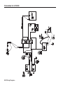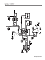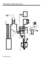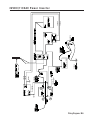
1
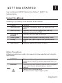
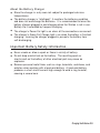
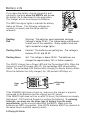
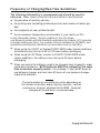
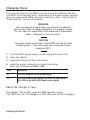
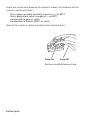
Operating &
Maintenance
Instructions
TC9876OI Rev. AJ 12/07
Monarch™
9876™
Mobile Work
Station (MWS™)
©2007 Paxar Americas, Inc. a subsidiary of Avery Dennison Corp. All rights reserved.
Each product and program carries a respective written warranty, the only warranty on
which the customer can rely. Paxar reserves the right to make changes in the product,
the programs, and their availability at any time and without notice. Although Paxar has
made every effort to provide complete and accurate information in this manual, Paxar
shall not be liable for any omissions or inaccuracies. Any update will be incorporated in
a later edition of this manual.
©2007 Paxar Americas, Inc. a subsidiary of Avery Dennison Corp. All rights reserved.
No part of this publication may be reproduced, transmitted, stored in a retrieval system,
or translated into any language in any form by any means, without the prior written
permission of Paxar Americas, Inc.
WARNING
This equipment has been tested and found to comply with the limits for a Class A digital
device, pursuant to Part 15 of the FCC Rules. These limits are designed to provide
reasonable protection against harmful interference when the equipment is operated in a
commercial environment. This equipment generates, uses, and can radiate radio frequency
energy and, if not installed and used in accordance with the instruction manual, may cause
harmful interference to radio communications. Operation of this equipment in a residential
area is likely to cause harmful interference in which case the user will be required to correct
the interference at his own expense.
CANADIAN D.O.C. WARNING
This digital apparatus does not exceed the Class A limits for radio noise emissions from
digital apparatus set out in the Radio Interference Regulations of the Canadian Department
of Communications.
Le présent appareil numérique n’émet pas de bruits radioélectriques dépassant les limites
applicables aux appareils numériques de la classe A prescrites dans le Réglement sur le
brouillage radioélectrique édicte par le ministère des Communications du Canada.
Trademarks
MONARCH® and 9876 are registered trademarks of Paxar Americas, Inc.
Paxar® is a trademark of Paxar Corporation.
Avery Dennison® is a trademark of Avery Dennison Corporation.
Avery Dennison Printer Systems Division
170 Monarch Lane
Miamisburg, OH 45342
TA B L E O F C O N T E N T S
GETTING STARTED . . . . . . . . . . . . . . . . . . . . . . . . . . . . . . . . . . . . . . . . . . . . . . . . . . . 1-1
Using this Manual . . . . . . . . . . . . . . . . . . . . . . . . . . . . . . . . . . . . . . . . . . . . . . . 1-1
Safety Precautions . . . . . . . . . . . . . . . . . . . . . . . . . . . . . . . . . . . . . . . 1-1
Audience. . . . . . . . . . . . . . . . . . . . . . . . . . . . . . . . . . . . . . . . . . . . . . . . . . . . . . 1-2
Ordering Programmer’s Manuals . . . . . . . . . . . . . . . . . . . . . . . . . . . . . . . . . . . 1-2
Calling Service . . . . . . . . . . . . . . . . . . . . . . . . . . . . . . . . . . . . . . . . . . . . . . . . . 1-2
ABOUT THE MWS . . . . . . . . . . . . . . . . . . . . . . . . . . . . . . . . . . . . . . . . . . . . . . . . . . . . . 2-1
Tools You May Need . . . . . . . . . . . . . . . . . . . . . . . . . . . . . . . . . . . . . . . . . . . . . 2-1
Handle Options . . . . . . . . . . . . . . . . . . . . . . . . . . . . . . . . . . . . . . . . . . . . . . . . . 2-2
Shelf Options . . . . . . . . . . . . . . . . . . . . . . . . . . . . . . . . . . . . . . . . . . . . . . . . . . 2-3
About the Doors . . . . . . . . . . . . . . . . . . . . . . . . . . . . . . . . . . . . . . . . . . . . . . . . 2-4
Attaching the Hanging Folders . . . . . . . . . . . . . . . . . . . . . . . . . . . . . . . . . . . . . 2-5
Connecting the Power Cord . . . . . . . . . . . . . . . . . . . . . . . . . . . . . . . . . . . . . . . 2-6
Connecting a Printer . . . . . . . . . . . . . . . . . . . . . . . . . . . . . . . . . . . . . . . . . . . . . 2-7
Using other Monarch Printers . . . . . . . . . . . . . . . . . . . . . . . . . . . . . . . 2-7
Using other Printers . . . . . . . . . . . . . . . . . . . . . . . . . . . . . . . . . . . . . . 2-7
CHARGING THE BATTERIES . . . . . . . . . . . . . . . . . . . . . . . . . . . . . . . . . . . . . . . . . . . . 3-1
Important Charging Information . . . . . . . . . . . . . . . . . . . . . . . . . . . . . . . . . . . . 3-2
About the Battery Charger . . . . . . . . . . . . . . . . . . . . . . . . . . . . . . . . . 3-3
Important Battery Safety Information . . . . . . . . . . . . . . . . . . . . . . . . . . . . . . . . 3-3
Battery Life . . . . . . . . . . . . . . . . . . . . . . . . . . . . . . . . . . . . . . . . . . . . . . . . . . . . 3-4
Frequency of Charging/Run-Time Guidelines . . . . . . . . . . . . . . . . . . . . . . . . . . 3-6
Changing Fuses . . . . . . . . . . . . . . . . . . . . . . . . . . . . . . . . . . . . . . . . . . . . . . . . 3-7
About the Charger’s Fuse . . . . . . . . . . . . . . . . . . . . . . . . . . . . . . . . . . 3-7
Table of Contents i
POWER OPTIONS . . . . . . . . . . . . . . . . . . . . . . . . . . . . . . . . . . . . . . . . . . . . . . . . . . . . . 4-1
Standard or Symbol 24VDC . . . . . . . . . . . . . . . . . . . . . . . . . . . . . . . . . . . . . . . 4-1
24VDC/115VAC Power Inverter . . . . . . . . . . . . . . . . . . . . . . . . . . . . . . . . . . . . 4-3
AC/DC Output (Power Inverter) . . . . . . . . . . . . . . . . . . . . . . . . . . . . . . . . . . . . 4-5
About the Inverter . . . . . . . . . . . . . . . . . . . . . . . . . . . . . . . . . . . . . . . . 4-5
Inverter LED Status . . . . . . . . . . . . . . . . . . . . . . . . . . . . . . . . . . . . . . 4-7
Using the Remote Switch . . . . . . . . . . . . . . . . . . . . . . . . . . . . . . . . . . 4-8
Printing . . . . . . . . . . . . . . . . . . . . . . . . . . . . . . . . . . . . . . . . . . . . . . . . . . . . . . . 4-8
About Sleep Mode . . . . . . . . . . . . . . . . . . . . . . . . . . . . . . . . . . . . . . . . . . . . . . 4-9
SPECIFICATIONS . . . . . . . . . . . . . . . . . . . . . . . . . . . . . . . . . . . . . . . . . . . . . . . . . . . . . A-1
Utility Cart . . . . . . . . . . . . . . . . . . . . . . . . . . . . . . . . . . . . . . . . . . . . . . . . . . . . A-1
Batteries . . . . . . . . . . . . . . . . . . . . . . . . . . . . . . . . . . . . . . . . . . . . . . . . . . . . . A-1
Charger . . . . . . . . . . . . . . . . . . . . . . . . . . . . . . . . . . . . . . . . . . . . . . . . . . . . . . A-2
Inverter . . . . . . . . . . . . . . . . . . . . . . . . . . . . . . . . . . . . . . . . . . . . . . . . . . . . . . A-2
WIRING DIAGRAMS . . . . . . . . . . . . . . . . . . . . . . . . . . . . . . . . . . . . . . . . . . . . . . . . . . . B-1
Standard 24VDC . . . . . . . . . . . . . . . . . . . . . . . . . . . . . . . . . . . . . . . . . . . . . . . B-2
Symbol 24VDC. . . . . . . . . . . . . . . . . . . . . . . . . . . . . . . . . . . . . . . . . . . . . . . . . B-3
WM 24VDC (DC/DC Converter) . . . . . . . . . . . . . . . . . . . . . . . . . . . . . . . . . . . . B-4
24VDC/115VAC Power Inverter . . . . . . . . . . . . . . . . . . . . . . . . . . . . . . . . . . . . B-5
24VDC/115VAC 1000W Power Inverter . . . . . . . . . . . . . . . . . . . . . . . . . . . . . . B-6
ii Table of Contents
1
G E T T I N G S TA R T E D
Use the Monarch® 9876™ Mobile Work Station™ (MWS™) for
mobile printing.
Using This Manual
Following is a summary of the contents of this manual.
Chapter
Contents
1
Getting Started
Contains information about the batteries and
MWS.
2
About the MWS
Describes how to connect power cords and use
additional devices on the MWS.
3
Charging the
Batteries
Describes how to charge the batteries.
4
Power Options
Describes battery power and battery safety issues.
5
Printing
Explains how to print supplies from a printer on the
MWS.
A
Specifications
Technical specifications about the MWS.
Safety Precautions
Following symbols are used in this manual to show importance of using the
MWS safely.
WARNING
Failure to follow the guidelines marked with this
symbol could result in serious personal injury or
death.
CAUTION
Failure to follow the guidelines marked with this symbol
could result in minor personal injury or product
damage.
Caution, risk of electrical shock.
Also known as the "High Voltage" symbol.
Getting Started 1-1
Audience
This manual is designed for the person using the MWS for mobile printing
applications.
After you receive the MWS, you should have all the necessary parts,
including the batteries and charger. Check inside ALL packaging
material. Make sure you do not throw away any pieces. Keep the boxes
and packaging material in case the MWS ever needs repair.
Ordering Programmer ’s Manuals
The Packet Reference Manual, which describes how to create format and
batch packets for printing labels, how to configure a Monarch® printer
online, and how to perform other advanced techniques is available from our
Web site.
Calling Service
If these solutions do not work or you have a problem not
listed, see your System Administrator or call Service at the
number listed on the back of this manual.
1-2 Getting Started
2
ABOUT THE MWS
The Mobile Work Station ships mostly assembled. This chapter
explains the different options and how to assemble any special
options, such as the hanging folders.
To o l s Yo u M a y N e e d
To assemble the options, you may need a flathead (common)
screwdriver; a Phillips screwdriver; wrenches: 7/16", 11/32", 1/4"
and adjustable; 5/32" Hex key (wrench); a rubber mallet and
hammer, and slip-joint or needle-nose pliers.
Check inside ALL packaging material. Make sure you do not
throw away any pieces.
Front of
MWS
Left Side
Back of
MWS
Right Side
About the MWS 2-1
Handle Options
There are different handle configurations and each option is pictured below.
One Curved Handle
You can have one or two curved handles.
Two Curved Handles
2-2 About the MWS
Shelf Options
You can have one or two shelves.
Shelf
To collapse the shelf, lift the shelf from the sides and allow it to swing down.
To extend the shelf, lift the shelf until the rear lip slides down onto the top of
the support brace and locks in place.
About the MWS 2-3
About the Doors
The MWS has combinations of doors and solid panels that do not open. The
doors should already be attached to the MWS.
Use water or a glass and surface cleaner to clean the
doors/panel. Do not use solvents on these
doors/panel. A solvent will damage the door/panel.
Doors
Doors
2-4 About the MWS
Attaching the Hanging Folders
Follow the steps below to attach the hanging folders to the MWS.
Doors must be installed before you can use the hanging
folder option.
You must attach the bottom folder to the MWS first.
1.
Remove the following items from their packaging:
(2) hanging folders
(4) Philips screws
2.
Locate the holes in the left-side panel. Using a Philips screwdriver,
start threading two screws in the two bottom holes.
3.
Hang the bottom folder onto the screws. Tighten the screws.
4.
Thread two screws in the top two holes.
5.
Hang the top folder onto the screws. Tighten the screws.
About the MWS 2-5
Connecting the Power Cord
Make sure to set the proper voltage on the charger voltage selector switch
on the right side of the charger (115V in U.S. or 230V International).
Incorrect voltage selection can result in charger failure. Connect the
charger's power cord to the power inlet. Power cords are not included with
International models. The charger's power switch is also on the right side.
Charger
Power
Switch
Power
Cord
Voltage
Selector
115
24VDC Charger
Power
Inlet
The battery's status LEDs are located on the left side of the Power Panel.
The MWS Power Switch is to the right of the LEDs. See Chapter 3,
"Charging the Batteries" for more information.
MWS
Power
Switch
Battery
Status LEDs
Power
Panel
Do not plug the external power cord into a wall outlet until you
are ready to charge the battery. See Chapter 3, "Charging the
Batteries" for important battery information.
2-6 About the MWS
Connecting a Printer
Contact your Monarch Representative for instructions on attaching a
Monarch® printer to the MWS.
Using other Monarch® Printers
Contact your Monarch Representative for instructions on connecting
Monarch® 9462™ and Monarch® 9465™ chargers to the MWS. This allows
you to keep the chargers close to where you are working on the sales floor.
For more information about using your 9462 or 9465 charger, refer to the
Operating Instructions provided with the charger.
The following printers are supported with these chargers:
u
Monarch® Sierra Sport2™ (9460™)
u
Monarch® Sierra Sport3™ (9433™)
u
Monarch® Pathfinder® Ultra® Silver (6032™)
u
Monarch® Pathfinder® Ultra® Platinum (6039™)
Additionally, a laptop or handheld computer (terminal) can be powered on
the MWS.
Using other Printers
Contact your Monarch Representative to attach non-Monarch printers to the
MWS.
About the MWS 2-7
2-8 About the MWS
C H A R G I N G T H E B AT T E R I E S
3
This chapter describes how to
u
charge the Mobile Work Station’s batteries
u
change the fuses.
The battery charger is a fully automatic, maintenance-free charger.
Make sure the voltage selector switch (located on the back of
the charger) is set for the proper voltage (115V or 220V).
Dispose of used batteries according to the manufacturer’s
instructions.
To charge the battery, plug the Mobile Work Station’s AC power
cord into a grounded outlet. Charge the battery:
u
before using the MWS for the first time (charge it for 7
hours)
u
when the MWS beeps (see “Battery Life” for indications of
low battery conditions)
u
when the MWS is not in use.
When the MWS is not in use, always leave the battery charger
plugged in and charging. The battery charger is “intelligent;” it
monitors the battery condition and does not overcharge the lead
acid battery. Battery life is extended by frequent charging.
CAUTION
Only qualified service personnel may install or
replace the two 12-volt (55 amp-hours) sealed
lead-acid non-venting batteries on the MWS.
If replacing batteries, you must use the same type of battery from the
same manufacturer (as the ones provided with the MWS). Make sure the
batteries are NRTL-recognized. Also, BOTH batteries MUST be replaced at
the same time to maintain capacity match.
Charging the Batteries 3-1
Important Charging Information
WARNING
DANGER! RISK OF ELECTRICAL AND FIRE HAZARD.
CERTAIN ACTIONS MAY RESULT IN DEATH, SERIOUS
INJURY, SHOCK, OR BURNS.
u
Do not disassemble the battery charger.
u
Do not operate the charger if it has been damaged in any way. Do not
spill liquids into the charger, such as water or soft drink.
u
Do not expose the battery charger to rain or snow. Never charge a
frozen battery. The colder the battery, the longer it takes to charge.
u
Plug only into a three-prong grounded outlet. Do not alter the AC power
cord or plug provided. Do not operate the battery charger with a
damaged cord or plug.
u
Do not let the battery remain fully or partly discharged for a long time;
keep it charged.
u
If using an extension cord, you must use 18 gauge or heavier for lengths
up to 50 feet, or 16 gauge or heavier for lengths up to 100 feet. Use of
improper extension cord could cause fire and electric shock. Use an
extension cord bearing the UL listing mark and rated for four Amperes or
greater current capacity.
u
Pull on the plug rather than the cord when disconnecting the battery
charger. Locate the cords where they will not be stepped on, tripped
over, or otherwise subjected to damage or stress.
u
The batteries must be charged when the total voltage is less than 21V.
The charger will not charge if the total voltage is less than 5V. If the
total voltage is less than 5V, you need new batteries.
3-2 Charging the Batteries
About the Battery Charger
u
Store the charger in a dry area not subject to prolonged sub-zero
temperatures.
u
The battery charger is “intelligent;” it monitors the batteries condition
and does not overcharge the batteries. It is recommended to leave the
battery charger plugged in and charging when the Station is not in use.
Battery life is extended by frequent charging.
u
The charger’s Power On light is on when all the connections are correct.
u
The charger’s Green Full Charge light is on when the battery is finished
charging. Leaving the charger plugged in prevents the battery from
self-discharging.
Important Battery Safety Information
u
Never smoke or allow a spark or flame in vicinity of battery.
u
Do not drop a metal tool on the battery. The resulting spark or
short-circuit on the battery of other electrical part may cause an
explosion.
u
Remove personal metal items such as rings, bracelets, necklaces, and
watches when working with a lead-acid battery. A lead-acid battery
produces a short-circuit current high enough to weld a ring to metal,
causing a severe burn.
Charging the Batteries 3-3
Battery Life
If you leave the battery charger plugged in and
constantly charging when the MWS is not in use,
the battery life is maximized for the application.
The charger will not overcharge the batteries.
The MWS has signal lights to indicate the battery
status as follows. The following voltages are
nominal (not exact) and should be used for
reference.
Charger
Status
LEDs
Flashing
Red
Warning! The batteries need immediate charging.
Voltage is below 22.5V. The station beeps continuously
to alert you of this condition. (Early models have red
lights instead of orange lights.)
Flashing Yellow
Caution! The batteries are getting low. The voltage is
between 22.5V and 23.5V.
Flashing Green
Go! The voltage is above 23.5V. The batteries are
charged to approximately 75% or better capacity.
The 24VDC charger has a Power LED and five Percentage LEDs. When the
charger is turned off (power LED off), the percentage LED shows battery
status. The percentage LED flashes while charging to display battery status.
When the batteries are fully charged, the 100 percent LED stays on.
100%
Power
LED
85%
70%
50%
30%
1
Percentage
LED
If the CHARGE light does not turn on, make sure the charger is properly
connected to the batteries and the charger has AC power.
If the READY light does not turn on after 18 hours, the batteries are deeply
discharged. Call Technical Support or replace the batteries. If replacing
batteries, you must use the same type of battery from the same
manufacturer (as the ones provided with the MWS). Make sure the
batteries are NRTL-recognized. Also, BOTH batteries MUST be replaced at
the same time to maintain capacity match.
3-4 Charging the Batteries
F r e q u e n c y o f C h a r g i n g / R u n -T i m e G u i d e l i n e s
The following information is approximate and should be used for
reference. Many factors effect an individual battery’s performance:
u
the presence of auxiliary devices
u
the printing rate (including printhead contrast and number of labels per
day)
u
the complexity of your printed formats
u
the environment (temperature and humidity in your facility or DC).
In the information below, “typical conditions” are as follows:
one Monarch printer printing standard compliance 4x6 labels (5-10 minutes
of actual printing per hour), no auxiliary devices attached to the MWS, and
standard environmental conditions (no excessive heat or humidity).
u
When using the 24VDC or Symbol 24VDC MWS under typical conditions,
the batteries may last up to 50 to 100 hours before recharging.
u
When using the AC Power Inverter or 24VDC/115VAC MWS under
typical conditions, the batteries may last up to 24 hours before
recharging.
u
When you notice the batteries need to be charged more frequently, order
replacement batteries. BOTH batteries MUST be replaced at the same
time to maintain capacity match. For example, if you had 60 hours of
use between charges and now have 30 hours of use between charges,
replace the batteries.
The performance of your batteries varies depending on
the number of printers and/or auxiliary devices, such as
a scanner or terminal, attached to the MWS. Frequent
charging of the batteries is recommended.
Charging the Batteries 3-5
Changing Fuses
There are two fuses for the MWS: one connecting the batteries and one
from BAT2 to the terminal block. Depending on the power option selected
when you ordered the MWS, the size of the fuses varies. See Chapter 4,
“Power Options,” for more information.
WARNING
You may observe a spark when you make this connection
since current flows to charge capacitors in the power inverter.
Do not make this connection in the presence of Flammable
fumes. Explosion or fire may result.
CAUTION
The power switch on the front of the MWS must be off while
changing fuses. (The status light near the power switch
should be OFF.)
1.
Turn the MWS’ power supply off and unplug the power cord.
2.
Open the cabinet.
3.
Unplug the fuses from the fuse holders.
4.
Insert the proper voltage fuse in each fuse holder.
Each fuse is labeled as 20A or 30A.
Fuse
Description
F1
20 A ATO (from BAT2 to the terminal block)
F2
20 A ATO (connects the batteries only for the DC power option)
30 A ATO (for the 300W, 24VDC Power Inverter option)
About the Charger ’s Fuse
The charger (12V or 24V) inside the MWS also has a fuse:
T4A 125V fuse (for 12V chargers) or T6A 125V fuse (for 24V chargers).
3-6 Charging the Batteries
4
POWER OPTIONS
Your MWS was ordered with one of these power options:
u
Standard 24VDC
u
Symbol 24VDC
u
24VDC/115VAC (uses the power inverter for AC power.
The power inverter is only 115V.)
u
AC/DC Output with the power inverter. The power inverter
is only 115V.
Make sure all packaging material is removed from the cabinet
before use.
Standard or Symbol 24VDC
20 Amp
Fuse Jumper
Connect, F2
Black
Wires
20 Amp Fuse, F1
BAT 2
BAT 1
BlackWire (-) to
Terminal Block
Green Wire
Ground to Station Floor
Red Stripe
Wire to Terminal Block
Power Options 4-1
Check the wiring for your batteries and charger.
Battery
Strap
Battery
Support
Ground Wires
Make sure the ground wire is attached using one M5 screw with two M4 nuts
and M4 washers as shown.
Keep the Mobile Work Station’s power switch ON when
continuously operating the MWS and/or printer(s). If the
MWS will be unused for extended periods of time, turn
OFF the Mobile Work Station’s power switch.
The MWS’ power switch controls the power to all printers. If using more
than one printer on the MWS, manually turn OFF each printer’s
power switch.
4-2 Power Options
24VDC/115VAC Power Inverter
The AC power inverter is only 115V. The AC power inverter uses battery
power, so the batteries may require more frequent charging.
WARNING
Remove ALL fuses from the cables before connecting ANY
cables to the batteries or switch. Make sure all the DC
connections are tight (torque to 9-10 ft-lbs, 11.7-13 Nm).
Loose connections overheat and could result in a potential
hazard.
Check the wiring for your batteries and charger.
30 Amp
Fuse Jumper
Connect, F2
Red Wire to
Inverter
BAT 2
20 Amp
Fuse, F1
BAT 1
Black
Wire (-) to
Terminal
Block
Green Wire
Ground to Station Floor
Red Stripe Wire
to Terminal
Red Wire to
Terminal Block
Make sure the proper voltage fuse is installed in each fuse holder.
Each fuse is labeled as 20A or 30A.
The batteries are connected with a 30 Amp fuse
BAT2 has a 20 Amp fuse from it to the terminal block.
Power Options 4-3
Make sure the ground wires are attached using one M5 screw with two M4
nuts and M4 washers as shown.
Battery
Strap
Battery
Support
Ground Wires
WARNING
This equipment contains components which can produce arcs
or sparks. To prevent fire or explosion, do not install near
Flammable materials or in locations that require
ignition-protected equipment (including gasoline-powered
machinery, fuel tanks, joints, or fittings).
4-4 Power Options
AC/DC Output (Power Inverter)
Uses the power inverter for AC power, along with the standard 24VDC for a
Paxar/Monarch printer. The power inverter is only 115V. The AC power
inverter uses battery power, which may require more frequent charging of
the batteries.
About the Inverter
WARNINGS
The inverter is designed to operate from a battery.
Performance cannot be guaranteed and damage can result
when the inverter is ran without the batteries installed!
Even if the MWS is not connected to an outlet, power is still
supplied to the inverter from the batteries and charger.
Therefore, all cables are always "live."
You may observe a spark when you make this connection
since current flows to charge capacitors in the power inverter.
Do not make this connection in the presence of Flammable
fumes. Explosion or fire may result.
Remove ALL fuses from the cables before connecting ANY
cables to the batteries or switch.
Make sure all the DC connections are tight (torque to 9-10
ft-lbs, 11.7-13 Nm). Loose connections overheat and could
result in a potential hazard.
Power Options 4-5
Check the connections between the inverter’s cables, the batteries and the
inverter’s switch as follows:
heavy-gauge
heavy-gauge
orange cable
orange cable
red cable assembly to positive (+) on BAT2
black cable to negative (-) on BAT1
to pole on switch
to Remote (RMT) on switch
None of the inverter’s cables are attached the terminal block.
Orange, Pole
Orange, RMT
Switch on the MWS Electrical Panel
4-6 Power Options
WARNING
You may observe a spark when you make this connection
since current flows to charge capacitors in the power inverter.
Do not make this connection in the presence of Flammable
fumes. Explosion or fire may result. Operation of the inverter
without a proper ground connection may result in an electrical
safety hazard.
Do not store anything inside the cabinet other than the batteries
and battery charger. The cabinet must remain locked at all times
and the key must be stored with qualified service personnel.
Inverter LED Status
Display Input Voltage
LED Status
DC 24V
GREEN (solid)
AC Power OK
RED Blink (fast)
Over-voltage protect
30.6
RED Blink (slow)
under-voltage protect
21.0
RED Blink (intermittent)
over-temperature protect
_
RED (solid)
over-load protect
>400W / 960W
Power Options 4-7
Using the Remote Switch
The Mobile Work Station’s On/Off switch should be used as a remote switch
to turn the inverter ON or OFF.
To do this:
1.
On the inverter’s front panel, set the ON/OFF/REMO switch to OFF or
REMO.
Set to
OFF/REMO
2.
Make sure the switch on the electrical panel is OFF.
3.
Make sure the orange wires are connected to the Remote Port (on the
inverter) and the RMT Switch on the electrical panel.
Printing
To print supplies from a Monarch printer on the MWS:
1.
Turn on the Mobile Work Station’s power supply and turn on the printer.
PRINT MODE
Ready
B
2. Press Feed/Cut to calibrate the supply. You are now ready to collect
data and print.
4-8 Power Options
To conserve the battery, make sure the Mobile Work Station’s power switch
is turned OFF when not in use OR when charging the batteries. For optimal
(shortest) charging time, turn off the MWS and printer while charging.
u
If you need to finish a batch, you can print while charging, as long as the
batteries are not too depleted. However, printing while charging is not
recommended on a frequent basis.
u
If the printer will be unused for extended periods of time, we recommend
leaving the printhead unlatched.
u
If the printer’s green power light blinks, you need to recharge the battery.
There is a small reserve of battery power to continue printing after the
green power light begins blinking.
u
You must recharge the battery when you see error 762 or “Battery Dead”
on the display because the printer is in a “lock-up” condition and does
not print until the battery is recharged.
u
The printer may slow down if the battery voltage drops below a certain
level. The printer continues to print at the reduced speed until the
batteries are charged and the printer is turned off and then back on.
See “Battery Life” in Chapter 3 for more information about charging the
batteries.
About Sleep Mode
If the Monarch printer is inactive for longer than 30 seconds, the printer
goes into sleep mode to conserve battery power. While in sleep mode, the
display backlight is turned off to conserve battery power. Once the printer
“wakes up,” the backlight turns on.
To “wake up” the printer, press any button on the control panel. The buttons
are active during sleep mode, so if you press Escape/Clear, the printer
“wakes up” and you enter the offline menu mode. You can also send any
data to the printer to wake it up. You do not lose any data sent to the
printer during sleep mode.
Power Options 4-9
4-10 Power Options
A
S P E C I F I C AT I O N S
Utility Cart
Height
Approximately 42 inches (1067 mm) depending on
selected options
Width
23 inches (584 mm)
Length
28 inches (711 mm)
Weight
Approximately 150 lbs (68 kg) depending on selected
options
Operating Limits
40°F to 95°F (5°C to 43°C) with thermal transfer
supplies
Storage: 15°F to 120°F (-9°C to 49°C)
Humidity: 5% to 90% non-condensing
Batteries
u
(2) 12-volt, 55 amp-hours, deep cycle batteries
u
Sealed lead-acid, non-venting (safety venting only), no
transportation restrictions
u
Shelf Life/Charge Retention:
1 month
3 months
6 months
u
97%
91%
85%
Cycle Use:
100% depth of discharge
50% depth of discharge
30% depth of discharge
approx. 250 cycles
approx. 550 cycles
approx. 1200 cycles
Cycle Life is approximate and many factors effect an individual battery’s
performance.
Specifications A-1
Charger
Input
117VAC 60Hz, 320VA (Volt Amps)
Output
24 Volts, 8 Amps DC
u
Electronic reverse polarity and short circuit-shutdown
u
Low voltage start (total battery voltage must be greater than 1V to
charge)
u
AC input fuse in AC input connector
Use only NRTL-listed accessories (National Recognized
Testing Lab).
Inverter
Input Voltage
21 to 30VDC
No Load Current
0.23A
Frequency
60 Hz
Output Voltage
110VAC +5%
Output Power
300W RMS (continuous)
Surge Power
400W RMS (1 second)
Output Waveform
Pure Sine Wave (THD<4%)
Typical Effeciency
75%
Operating
Temperature
32°F to 105°F (0°C to 40°C)
A-2 Specifications
B
WIRING DIAGRAMS
This appendix contains wiring diagrams for the various power
options:
u
Standard 24VDC
u
Symbol 24VDC
u
WM 24VDC (DC/DC Converter)
u
24VDC/115VAC Power Inverter
WARNING
Only qualified service personnel may install or
replace the two 12-volt sealed lead acid batteries
used to power the printer on the Station.
If a battery needs to be replaced, BOTH batteries MUST be replaced at the
same time to maintain capacity match.
One or two power sparks may occur (this is normal) when installing or
changing the fuses.
Wiring Diagrams B-1
B-2 Wiring Diagrams
126523
126523
126491 or 126803
124589
L
G
N
Standard 24VDC
126763
126523
126523
126678
126759
126762
126490
126491 or 126803
126769
126624
126490
126679
126768
L
G
N 126575
126679
126679
126761
126471
126769
126473
Symbol 24VDC
Wiring Diagrams B-3
BATTERY
JUMPER CONNECT
30 AMP FUSED (F2)
PART# 124845
30
B-4 Wiring Diagrams
ATO
AMP
fuse
Batt. #1
PART#
126523
Batt.
#2
PART#
126523
DC to DC converter
125393
117592
GND
HARNESS
BATTERY
wire
wire
GREEN
Black
20
AMP
ATO
fuse
BLACK
WIRE
124587
MAIN PWRMINUS
124592
HARNESS,
FUSED 20A
MAIN (F1)
CHARGER
PART#
125358 or 126803
CHARGER
HARNESS
(ATTACHED
TO CHARGER)
117597
JUMPER
GRN/YEL
+24V
24V_SW
NOT
USED
GND
TERM. BLCK
RED/BLK
OR RED
WIRE
PART# 124930
PRINTER & RELAY PWR HARNESS
"PRT PWR"
Red wire 125391
Black wire 125392
wire
FUSED
118721
JUMPER
SAFETY GND
124586
IEC CORD
CHARGER
TO INLET
BLUE
L
BROWN
G
117597
JUMPER
119262
IEC
INLET
SWITCH
#124828
N
86
85
BATTERY
STATUS BOARD
124602
+
124930
PRINTER
&RELAY PWR
HARNESS
"AUX PWR"
124591
BATTERY STATUS BD HARNESS
124924
117597
JUMPER
30
87
supply
for
terminal
125390
WM 24VDC (DC/DC Converter)
126763
126766
126765
126523
126523
125584
126678
126759
126762
126767
126764
126764
126491 or 126803
126624
126490
126681
126679
126575
126679
126761
126764
126764
126473
24VDC/115VAC Power Inverter
Wiring Diagrams B-5
Visit www.paxar.com for sales, service,
supplies, information, and telephone numbers
for our locations throughout the world.
TOLL FREE:
1-800-543-6650 (In the U.S.A.)
1-800-363-7525 (In Canada)