1
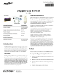
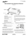
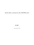
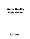
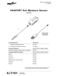
Instruction Sheet 012-12917A General Flow Sensor PS-2222 PS-2222 General Flow Sensor Low Pressure Tube Threaded Hole (1/4”-20) High Pressure Tube Luer Plug, Female Luer Barb, Male Included Included General Flow Sensor (PS-2222) PASPORT Sensor Extension Cable (PS-2500) Required Items* Information* PASCO Interface see www.pasco.com PASCO Data Acquisition Software see www.pasco.com *See the PASCO catalog or the PASCO web site at www.pasco.com for more information. Accessories used with the sensor Accessories used with the sensor ME-2220 Venturi Tube ME-2221 Pitot Tube Other Other ME-2224 Pressure Tap CI-9874 Sensor Handles (4 Pack) Model No.PS-2222 Product Description Product Description The PS-2222 General Flow Sensor is a versatile device for measuring differential pressure in air or water. It measures the difference in pressure between the two input tubes. The PASCO General Flow Sensor is designed to work with the ME-2220 Venturi Tube or the ME-2221 Pitot Tube. The Venturi Tube and Pitot Tube attach to the General Flow Sensor by way of a flexible twin tube hose. The connectors on the sensor are reversed from the connectors on the Venturi Tube and Pitot Tube so that they cannot be attached incorrectly. Using the PASCO data acquisition software, the user can select which device is attached to the sensor and what fluid (air or water) is flowing through the device. Once these selections are made, the sensor provides the pressure and the calculated values for flow velocity or volumetric flow (assuming standard temperature and pressure). The units of measure are selectable as metric or non-metric. Venturi Tube (ME-2220) The General Flow Sensor measures the fluid pressure in two areas of different diameter and calculates the speed from the difference in pressure. Slip Joint Flow Direction High Pressure Tube Inlet area = 3.44 x 10⁻⁴ m2 Throat area = 1.24 x 10⁻⁴ m2 Slip Joint Hose Length is 3 feet (0.91 m) Low Pressure The Venturi Tube is designed Tube to be used with standard 3/4 inch (1.91 cm) diameter polyvinyl chloride (PVC) pipe. ME-2220 Venturi Tube The inlet cross-sectional area of the Venturi Tube is 3.44 x 10⁻⁴ m2 (3.44 cm2) and the throat cross sectional area is 1.24 x 10⁻⁴ m2 (1.24 cm2). The plastic used in the Venturi Tube is compatible with standard PVC glues and it is recommended that it be glued into a piping network to measure flow rates. Alternatively, the Venturi Tube may be temporarily placed in a piping network using tape. The hose length is three feet (0.91 m). ® 2 Model No.PS-2222 Product Description Pitot Tube (ME-2221) The Pitot Tube is designed to measure flow velocity in open channels. The Pitot Tube has a detachable handle attached to a 1/4”-20 nut.The overall hose length is 6 feet (1.82 m). The tube with the male luer plug is for low pressure measurement and the other tube is for high pressure measurement. Static Taps Flow Direction Static Taps (evenly spaced around circumference) Fluid Inlet Handle Stagnation Point Low Pressure Tube 1 2 P = --- V 2 High Pressure Tube Overall hose length is 6 feet (1.82 m) Luer Plug, Male To Sensor ME-2221 Pitot Tube Quick Start • • Plug the General Flow Sensor into one of the PASPORT input ports of a PASCO interface (such as the 850 Universal Interface, Xplorer GLX, or SPARK Science Learning System). Or, connect the sensor to the PASPORT Sensor Extension Cable and then connect the cable to an input port. Connect an accessory such as the ME-2220 Venturi Tube or the ME-2221 Pitot Tube to the General Flow Sensor. Interface PASPORT Input Port Sensor • Start the PASCO data acquisition software (such as PASCO Capstone). Select the type of fluid (air or water). Set up a data display in the software. • Click “Record” data. • SETUP: For more information on setting up the software and recording data, refer to the end of this document or the User’s Guide and online help for the data acquisition software. , press the button on the GLX, or touch ‘Start’ to begin recording Specifications The pressure sensing element used in this sensor will provide accuracy of ±2.5% of the full scale reading (50 kilopascal) at temperatures between 0 and 85 degrees C. This implies accuracy within ±1.25 kPa. Better accuracy may be attained by doing a calibration of the sensor at the temperature of use and maintaining the sensor in a stable position. ® 3 General Flow Sensor Critical Use Considerations For low flow Venturi measurements at a rate of 1 standard cubic foot per minute (SCFM), the measured value of Pdiff was approximately 11 pascals (Pa) and the theoretical Pdiff was 6 Pa. These are uncorrected values with a baseline noise level of approximately 3 Pa. Repeatability is excellent with a variation within the noise band. Item Value Range: 0 to 50 kPa Differential Pressure Accuracy: ±2.5% of Full Scale (at 50 kPa) • Venturi Tube in Water ±2.1 gallons per minute (gpm) • Venturi Tube in Air ±2.5 scfm Repeatability: 0.25% of Full Scale (at 50 kPa) Resolution: 0.02% of Full Scale General Flow Sensor with the Venturi Tube and Pitot Tube Item Value with Venturi Tube Value with Pitot Tube Range - Water: 0 to 0.00530 m3/s (0 to 84 gpm) 0 to 9.98 m/s (0 to 22.3 miles per hour) Range - Air: 0 to 0.0488 m3/s (0 to 773 gpm) 0 to 92.1 m/s (0 to 206 mph) Critical Use Considerations Maximum Operating Pressure Do not subject the sensor to gauge pressures greater than 29 pounds per square inch (psi) or 200 kilopascals (kPa) as permanent damage will occur. Do not use the sensor to measure flow in systems pressurized to more than 29 psi. Note that municipal water systems normally exceed this value. Maximum Differential Pressure The maximum differential operating pressure between the high pressure and low pressure input is 7.25 psi or 50 kPa. Differential pressures greater than 7.25 psi may result in permanent damage to the sensor causing inaccurate measurement. High Pressure/Low Pressure Reversal Operation of the sensor with reversed pressure applied (the pressure applied to the low pressure port is higher than the pressure applied to the high pressure port) may result in permanent damage to the sensor. Changing Fluid Use Care must be taken when changing from measurement in liquids to measurement in gases. It is normal for small amounts of liquid to migrate into the hoses during use. This may be minimized by insuring that the hoses are tightly attached to the sensor prior to introducing liquids to the system. The large diameter of the venturi and pitot tube hoses minimizes capillary flow. Placing a high point in the hoses above the fluid level in the systems will also help limit fluid migration. After fluid use, hoses from the Venturi or Pitot Tube should be carefully blown clear of any migrated fluid and dried prior to use measuring a gas such as air. Fluid left in the line may obstruct flow causing inaccurate measurement. Fluid may also vaporize during use causing inaccurate measurement of flow. 4 ® Model No.PS-2222 Critical Use Considerations Setup and Use of the General Flow Sensor Connect the Sensor Connect tubes from either the Venturi Tube (ME-2220) or the Pitot Tube (ME-2221) to the General Flow Sensor. Be sure that connections are sealed prior to the introduction of any liquids to the system. Plug the General Flow Sensor PS-2222 into a PASPORT input port on a PASPORT-compatible interface, and turn on the interface. (Check the PASCO web site for compatible interfaces.) If you are using a computer, make sure that the interface is connected to the computer and turned on. Prepare the PASCO Capstone Data Acquisition Software • In the PASCO Capstone software, click the “Hardware Setup” icon in the Tools palette to open the “Hardware Setup” panel. Confirm that the General Flow Sensor icon appears with the interface’s icon. Interface icon General Flow Sensor icon Hardware Setup Panels • Click the “Data Summary” icon in the Tools palette to open the “Data Summary” panel. The panel lists the sensor’s measurements (for example, Differential Pressure (Diff Press kPa)). • To select the units of measure or make other changes to the measurement properties, select the parameter in the Sensor Data Summary panel, and then click the “Properties” icon (shaped like a gear) to open the Properties panel. To change units, click “Names and Symbols”. Both metric and non-metric units are selectable. Data Summary Panel • In the event that a fluid other than air or water is used, input appropriate values for density in the user input values in the PASCO Capstone software. Sensor Measurement Properties Set Up a Data Display • Set up a data display. For example, drag the Graph icon from the Displays palette onto the workbook page, or double-click the icon to create a Graph display. Graph display icon Create a Graph display ® 5 General Flow Sensor • Critical Use Considerations Set up the Graph display to show one of the sensor’s measurements on the vertical axis. For example, click the “Select Measurement” menu button on the vertical axis and pick “Diff Press (kPa)” from the menu. “Time (s)” automatically shows on the horizontal axis. Zeroing the Sensor Prior to measurement the sensor should be placed in its operational position, any fluids to be used should be introduced to the system and hoses should be restrained. Immediately prior to a data run the unit should be zeroed using the PASCO Capstone software zero function. Zero drift can occur due to temperature, position or hose placement changes. SPARKvue Setup • When SPARKvue starts up, it shows the Home Screen for a moment, and then shows a screen that lists the parameters for the General Flow Sensor, such as “Diff Press” in “psi”, “Pa”, and “in of Hg”. SPARK SLS screen for the General Flow Sensor • Select a parameter to display on a graph. For example, touch “Diff Press psi” and then touch “Show. A graph display of Diff Press (psi) versus Time (s) opens. Example: Touch “Diff Press” and then touch “Show” • Touch the Start ( ) button to begin recording data. • Touch the Stop ( ) button to end data recording. Touch “Start” SETUP: For more information on setting up the data acquisition software and recording data, refer to the User’s Guide and the online help for the software. Graph Display 6 ® Model No.PS-2222 Suggested Laboratory Activities Xplorer GLX Setup Make sure that the Xplorer GLX is turned on, and insert the General Flow Sensor into one of the PASPORT input ports at the top of the GLX. • In the GLX Home screen, use the cursor buttons to highlight “Sensors” and then press the “Checkmark” button. • In the General Flow Sensor screen, use the “Up” and “Down” cursor buttons to select a choice such as “Pitot Air” and then press the “Checkmark” button to change the selection from “Visible” to Not Visible”, or vice versa. • Press the “Home” button to return to the Home screen, and use the cursor buttons to select a display. Press the “Checkmark” button to open your display choice. Care After use with fluids, care should be taken to remove all fluid from the hoses that attach the sensor to the Venturi Tube or the Pitot Tube. Fluids left in the hoses may migrate into the sensor and cause damage over time. Suggested Laboratory Activities Visit the PASCO Web site at www.pasco.com and enter PS-2222 in the Search window. Click the User Resources tab to see the Downloads menu for the downloadable suggested activity write-ups. Activities may be similar to the following: • Derivation of the Venturi Pressure Velocity Relationship • Pump Delivery Studies - Measure fluid velocity as a function of pump speed and working head • Measurement of Velocity and Pressure Losses in Piping Networks (when used with the PS-2107 Absolute Pressure Sensor and the ME-2224 Pressure Tap) • Measurement of Velocity and Pressure Losses in Valves (when used with the PS-2107 Absolute Pressure Sensor and the ME-2224 Pressure Tap) ® 7 General Flow Sensor Suggested Laboratory Activities Technical Support For assistance with any PASCO product, contact PASCO at: Address: PASCO scientific 10101 Foothills Blvd. Roseville, CA 95747-7100 Web: www.pasco.com Phone: Email [email protected] +1 916-786-3800 (worldwide) 800-772-8700 (U.S.) For the latest information about the General Flow Sensor, visit the PASCO web site at www.pasco.com and enter “PS-2222” in the Search window. Limited Warranty For a description of the product warranty, see the PASCO catalog. Copyright The PASCO scientific Instruction Sheet is copyrighted with all rights reserved. Permission is granted to non-profit educational institutions for reproduction of any part of this manual, providing the reproductions are used only in their laboratories and classrooms, and are not sold for profit. Reproduction under any other circumstances, without the written consent of PASCO scientific, is prohibited. Trademarks PASCO, PASCO Capstone, PASPORT, SPARK Science Learning System, SPARK SLS, and SPARKvue are trademarks or registered trademarks of PASCO scientific, in the United States and/or in other countries. For more information visit www.pasco.com/legal. Product End of Life Disposal Instructions: This electronic product is subject to disposal and recycling regulations that vary by country and region. It is your responsibility to recycle your electronic equipment per your local environmental laws and regulations to ensure that it will be recycled in a manner that protects human health and the environment. To find out where you can drop off your waste equipment for recycling, please contact your local waste recycle/disposal service, or the place where you purchased the product. The European Union WEEE (Waste Electronic and Electrical Equipment) symbol (to the right) and on the product or its packaging indicates that this product must not be disposed of in a standard waste container. 8 ®