1
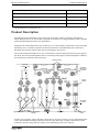
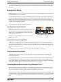
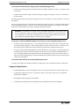
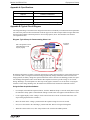
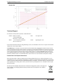
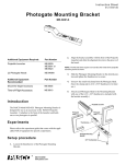
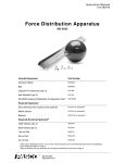
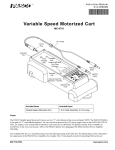
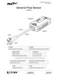
Instruction Sheet
012-14176A
Charge/Discharge Circuit
EM-8678A
Included Items
Information
Charge/Discharge Circuit
EM-8678A
Light Bulbs, #14 GE mini-screw (3)
EM-8627 (pack of 25)*
*Order EM-8627 for replacement bulbs. See the PASCO catalog or web site at www.pasco.com for more information.
Required Items
Information
AA* Batteries (2)
PI-6601 (pack of 4)
Banana Plug Patch Cords
SE-7123 (set of 8)
*AAA Batteries can also be used in the EM-8678A Charge/Discharge Circuit.
Model No.EM-8678A
Product Description
Additional Equipment Recommended for Experiments
Information*
PASCO Interface (such as UI-5000 850 Universal Interface)
See PASCO web site
PASCO Data Acquisition Software (such as PASCO Capstone)
See PASCO web site*
PASPORT Voltage/Current Sensor
PS-2115
Power Supply (Low Voltage)
See PASCO web site*
*See the PASCO web site at www.pasco.com.
Product Description
The EM-8678A Charge/Discharge Circuit can be used for the study of Ohm’s Law, battery and capacitor
charge/discharge rates, or for various other experiments in electronics. The Charge/Discharge Circuit is included
in the EX-9949 and EX-9953 Ohm’s Law Experiments.
Mounted to the circuit board are three types of resistors (10, 33, and 100 ohm), a double-throw switch, three light
bulb holders, and a 1.0 farad (F) capacitor. The board also includes 15 shrouded banana jack connectors for
attaching leads and cables and one empty slot for connecting any other devices.
The circuit board also has holders for two AA or AAA batteries, which would provide the main power supply to
the circuit. The resistors and light bulbs connect to a common ground (negative terminal) through the conductive
electrical pathway on the lower half of the board.
Battery holders
Capacitor,
1.0 farad, 5 volt
Shielded
banana jack
connector
Charge
position
Discharge
position
Light bulb holders
Common conductive
pathway
Resistors
Empty slot
Double-throw
switch
Auxiliary power supplies, sensors, and other external devices can also be connected. A set of short banana patch
cords is recommended for making connections between or into other leads. A Voltage/Current Sensor can be
connected to measure voltage and current in the circuit and discharge rates for the capacitor.
®
2
Model No.EM-8678A
Equipment Setup
Using the Charge/Discharge Circuit with a sensor such as the Voltage/Current Sensor requires a PASCO computer interface and data acquisition software (such as the UI-5000 850 Universal Interface and UI-5400 PASCO
Capstone).
Equipment Setup
You will need two “AA” or “AAA” batteries (not included), three #14 GE Mini Light Bulbs (included), and a set
of banana plug patch cords (not included).
For real-time data recording*, you will need a PASPORT Voltage/Current Sensor and a PASCO computer interface with data acquisition software (such as the UI-5000 850 Universal Interface and UI-5400 PASCO Capstone). NOTE: If you use the PASCO Capstone software, you can also use the ScienceWorkshop CI-6503 Voltage
Sensor and the ScienceWorkshop CI-6556 Current Sensor with either the UI-5100 850 Universal Interface or the
CI-7650 750 ScienceWorkshop Interface.
*See Appendix B for a typical experiment setup option.
Inserting/Replacing the Batteries
When inserting the batteries, follow the orientation for the positive and negative ends of the batteries shown on the battery
holders. A set of AA alkaline batteries can be ordered from
PASCO (PI-6601 pack of 4).
+
+
Inserting batteries into the battery holders
For Ohm’s law studies, alkaline batteries or re-rechargeable
batteries can be used.
Inserting/Replacing the Light Bulbs
A set of three 3-volt light bulbs comes with the Charge/Discharge Circuit. To remove a burnt out bulb, turn the
bulb counterclockwise and lift out. To replace a bulb, insert the bulb into one of the plastic slots (slot A, B, or C)
and turn the bulb clockwise until it fits tightly into the slot. For the bulb to light, the bulb tip must maintain contact with the metal piece in the slot.
CAUTION: To avoid overloading the circuit, do not use bulbs greater than a 3 volt capacity.
Using the Double-Throw Switch
The double-throw switch is used to control the path of the electrical current through the components on the
Charge/Discharge Circuit.
For the Ohm’s Law circuit, for example, when the switch lever is in the “Charge Position,” energy from the batteries can be routed to the capacitor. Moving the lever to the “Discharge Position” allows the capacitor to discharge energy through a resistor or light bulb or other component that is connected. For example, if a light bulb is
connected, as the energy dissipates as heat and light, the bulb slowly becomes dim.
Connecting External Devices to the Charge/Discharge Circuit
The Charge/Discharge Circuit was designed to be used with PASCO sensors, meters, and external power supplies. Connecting an external device requires a set of banana plug patch cords (i.e. at least one positive and one
negative banana patch cord, such as the SE-7123 Banana Plug Patch Cords (set of 8)).
The board has three positive, three negative, and nine neutral (unlabeled) shrouded banana jack connectors. The
connectors with the (+) label are for inserting positive leads and the connectors with the (-) label are for inserting
negative leads. The neutral connectors are for connecting either positive or negative leads, depending on your
setup.
®
3
C h a r g e / D i s c h a r g e C i r c u it
Equipment Setup
To Connect an External Power Supply to the Charge/Discharge Circuit
•
Connect the cord from the positive terminal on the power supply to the positive “Power(+)” connector on the
circuit board.
•
Connect the cord from the negative terminal on the power supply to the negative “Power(-)” connector on
the circuit board.
CAUTION: When using an external power supply, do not exceed a voltage of 3 volts for the bulbs or 5 volts for
the capacitor.
Also, always connect the positive lead from an external power supply to a positive (+) connector and the negative
cord to a designated negative (-) connector on the circuit board. Reversing positive and negative cord connections from an external power source may permanently damage the capacitor.
WARNING: To avoid shock, never place water or a wet hand in the path of the circuit. Always connect an external power supply to a properly grounded electrical outlet. Do not get the board or any
of its components wet. Do not place the board near water. Follow standard electrical safety precautions, and treat the Charge/Discharge Circuit like any other conductor.
To Connect a PS-2115 PASPORT Voltage-Current Sensor to the Charge/Discharge Circuit
•
To measure voltage: Plug the positive (+ red) voltage lead from the sensor into a positive connector on the
circuit board. Plug the negative (- black) voltage lead into a negative connector on the circuit board. (Note:
The connection of the leads from the sensor must be in parallel with a component of the circuit.)
•
To measure current: Plug banana plug patch cords into the positive (+) and negative (-) banana plug ports on
the Voltage-Current Sensor. Connect the Voltage-Current Sensor in series with the Charge/Discharge Circuit. For example, plug the patch cord from the positive banana plug port on the sensor into the “Power (+)”
connector on the Charge/Discharge Circuit board. Plug the other patch cord from the sensor into the positive
connector for the capacitor.
To Connect Other Devices to the Charge/Discharge Circuit
Two empty slot springs are available for adding (or testing) other types of components with the circuit board.
Suggested Applications
4
•
Demonstrating Ohm’s Law, the relationship of current to voltage and resistance in a direct current circuit.
•
Comparing the voltage-current curve for an ohmic resistor to the voltage-current curve for a light bulb
(which may be nonlinear).
•
Measuring the charge-discharge of the capacitor.
•
Comparing battery discharge rates for different types of rechargeable batteries (not included).
®
Model No.EM-8678A
Equipment Setup
Appendix A: Specifications
Item
Information
Capacitor
1.0 farad, 5 volt maximum
Resistors
10 ohm, 33 ohm and 100 ohm, 5 volt maximum
Light Bulbs
3 volt maximum
Board
18.3 by 13 centimeters composed of fiberglass
Appendix B: Typical Circuit Diagram
The Charge/Discharge Circuit board was designed to allow the user flexibility in measurement and experimentation. The lower portion of the board contains a built-in copper circuit with a lacquer finish. The upper half of the
board provides multiple connection points for various setup options. (Note: The board does not contain a
series-parallel circuit.)
Diagram: Typical Setup for Demonstrating Ohm’s Law
Note: The appearance of the
Charge/Discharge Circuit
may vary slightly.
To PASCO
Interface
By allowing the batteries to charge a capacitor connected to a resistor, this setup may be used to study Ohm’s law
in “real time” (that is, seeing the current and voltage dynamically change). When the switch is moved to the
charge position, the battery charges the capacitor. When the switch is moved to the discharge position, the capacitor discharges through the resistor. In the PASCO data acquisition software, plot the voltage vs. the current
during “Discharge” for each separate run. The slope of the graph is resistance. To see the effect of varying the
resistance on the voltage discharge rate, the student can switch the lead connections to different resistors.
Using the Data Acquisition Software
•
For example, in the PASCO Capstone software, click the “Hardware Setup” icon in the Tools palette to open
the “Hardware Setup” panel. Confirm that the Voltage-Current Sensor icon appears with the interface’s icon.
•
Create a graph display. Select “Voltage” for the vertical axis and “Current” for the horizontal axis. (The
slope of this graph will be the resistance.)
•
Move the switch to the “Charge” position and let the capacitor charge for 20 to 30 seconds.
•
Next, move the switch to the “Discharge” position and click ‘Record’ to begin collecting data.
•
When the current reaches zero, click ‘Stop’ and move the switch to the middle position.
®
5
C h a r g e / D i s c h a r g e C i r c u it
Equipment Setup
Sample Data
Technical Support
For assistance with any PASCO product, contact PASCO at:
Address: PASCO scientific
10101 Foothills Blvd.
Roseville, CA 95747-7100
Web:
www.pasco.com
Phone:
Email
[email protected]
+1 916-786-3800 (worldwide)
800-772-8700 (U.S.)
For the latest information about the Charge/Discharge Circuit, visit the PASCO web site at www.pasco.com and enter
“EM-8678A” in the Search window.
Limited Warranty For a description of the product warranty, see the PASCO catalog. Copyright The PASCO scientific Instruction
Sheet is copyrighted with all rights reserved. Permission is granted to non-profit educational institutions for reproduction of any part of
this manual, providing the reproductions are used only in their laboratories and classrooms, and are not sold for profit. Reproduction
under any other circumstances, without the written consent of PASCO scientific, is prohibited. Trademarks PASCO, PASCO Capstone, PASPORT, SPARK Science Learning System, SPARK SLS, SPARKvue and ScienceWorkshop are trademarks or registered
trademarks of PASCO scientific, in the United States and/or in other countries. For more information visit www.pasco.com/legal.
Product End of Life Disposal Instructions:
This electronic product is subject to disposal and recycling regulations that vary by country and region. It is your
responsibility to recycle your electronic equipment per your local environmental laws and regulations to ensure that it
will be recycled in a manner that protects human health and the environment. To find out where you can drop off your
waste equipment for recycling, please contact your local waste recycle/disposal service, or the place where you purchased the product.
The European Union WEEE (Waste Electronic and Electrical Equipment) symbol (to the right) and
on the product or its packaging indicates that this product must not be disposed of in a standard
waste container.
6
®