1
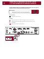
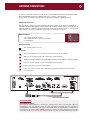
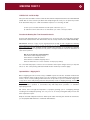
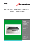
T 3 Amplifier
Owner’s Guide
THANK YOU!
Congratulations and Thank You for Choosing Parasound
Your new Parasound Halo T 3 Tuner presents the latest advancements in tuner technology.
The T 3 is built to the strict quality and performance standards set by Parasound. We’re
proud to offer you this exceptional audio component that will bring you many years of
enjoyment and dependability.
Here at Parasound, we design our products to perform at a higher level of flexibility
and sonic performance than you may have expected. We encourage you to read this
entire manual to learn all the features and capabilities of your new Halo T 3 Tuner.
If you’re eager to get up and running right away, simply follow the basic step-by-step
instructions to connect and operate the T 3. If you want to learn about some of the
technical and design aspects of your T 3, refer to the Technically Speaking and Design
Overview sections in the back of the manual. If you run into difficulties, the Troubleshooting
Guide should help you quickly remedy the problem.
We appreciate you taking the time to read these instructions and thank you for selecting
Parasound for your listening pleasure.
The Parasound Staff
Keeping Records for Future Reference
Record the serial number located on the bottom of your T 3 in the space below. Also note
your Parasound Deale’s name and phone number. We recommend that you keep your
purchase receipt with this manual and store them both in a safe place. You may need to
refer to this information sometime in the future.
Parasound T 3 Tuner Serial #:__________________________
Parasound Dealer: ____________________________________
Phone Number:_______________________________________
Date of Purchase: _____________________________________
YOU SHOULD KNOW
There is no Parasound warranty for this unit if it was not purchased from an Authorized
Parasound Dealer. Investigate any warranty claims made by unauthorized dealers very
carefully as you will need to depend entirely upon the dealer, and NOT upon Parasound.
Unauthorized dealers may lack the capability to arrange repairs of Parasound equipment.
Authorized Parasound Dealers are listed at www.parasound.com or you can call 415-397-7100
between 8:30 am and 4:30 pm Pacific time.
A missing or tampered serial number could indicate that this unit was stolen or sold by an
unauthorized dealer. You should return it to your dealer immediately for replacement or a full refund.
TABLE OF CONTENTS
T 3 Tuner
1
UNPACKING AND PLACEMENT GUIDELINES FOR THE T 3
_________________________________________________________________________________
2
CONNECTING THE BALANCED AUDIO OUTPUTS FROM THE T 3
TO YOUR PREAMPLIFIER OR SURROUND CONTROLLER
_________________________________________________________________________________
3
CONNECTING THE UNBALANCED LINE OUTPUT 1 ON THE T 3
TO YOUR PREAMPLIFIER OR SURROUND CONTROLLER
_________________________________________________________________________________
4
ANTENNA CONNECTIONS
_________________________________________________________________________________
6
CONNECTING AN INFRARED REPEATER SYSTEM TO YOUR T 3
_________________________________________________________________________________
7
TURNING THE T 3 ON AND OFF WITH AN EXTERNAL +9 VDC
TO +12 VDC TRIGGER VOLTAGE
_________________________________________________________________________________
8
TRIGGERING ANOTHER COMPONENT FROM THE T 3’S 12V
LOOP OUTPUT JACK
_________________________________________________________________________________
9
RS232 CONTROL
_________________________________________________________________________________
10
CONNECTING THE AC POWER CORD TO THE T 3
_________________________________________________________________________________
12
OPERATING YOUR T 3
_________________________________________________________________________________
18
FRONT PANEL AND REMOTE CONTROL
_________________________________________________________________________________
19
TROUBLESHOOTING GUIDE
_________________________________________________________________________________
20
SERVICING YOUR T 3
_________________________________________________________________________________
21
TECHNICALLY SPEAKING
_________________________________________________________________________________
22
PARASOUND T 3 DESIGN OVERVIEW
_________________________________________________________________________________
23
T 3 SPECIFICATIONS
_________________________________________________________________________________
1
UNPACKING AND PLACEMENT GUIDELINES FOR THE T 3
Unpacking Your T 3
Carefully unpack your T 3 from the shipping carton and remove all the enclosed accessories:
•
•
•
•
•
•
Remote control with two AAA batteries
Detachable AC cord
FM Folded Dipole 300 Ω Antenna
FM 300 ohm to 75 Ω balun matching transformer
AM loop antenna
Trigger control wire with a 2.5 mm sub-mini plug on each end.
While you are unpacking your new tuner, inspect it thoroughly for possible shipping damage. If
you see any, contact your Parasound dealer right away. Be sure to save and store both the inner
and outer cartons and packing inserts for possible future transport. To save room for storage, you
can cut the seams on the bottom of the cartons and flatten them.
Placement Guidelines of Your T 3
For trouble-free operation and long-term reliability, please follow the simple guidelines below to
help decide where to locate your T 3 in your system.
• Place the T 3 on a separate shelf that will adequately support its weight.
• Keep it away from heat sources such as air ducts or radiators.
• Leave at least 1” of space on all sides and the top. This helps facilitate passive
heat dissipation.
• Keep it away from computers that may interfere with its reception.
Rack Mounting Your Parasound T 3
If you plan to mount the T 3 into a standard 19” wide equipment rack, you will need to purchase
the optional Parasound HRA 2 Rack Mount Adapter. With its four feet removed, the T 3 chassis
and front panel height occupies two rack spaces (3-1/2” or 88mm). When mounting equipment
below the T 3, you will also need to allow about 1/8” below the unit for the bottom chassis
screws. A single standard rack space allows 1-3/4” horizontal inches in a 19-inch wide
equipment rack. This measurement standard was developed by the EIA (Electronic Industries
Association) so manufacturers of electronic components and equipment racks could build
products in standardized heights that would fit in a uniform space. Please call your Parasound
dealer or call directly to Parasound Technical Services if you need additional advice about rack
mounting the T 3.
CONNECTING THE BALANCED AUDIO OUTPUTS FROM THE
T 3 TO YOUR PREAMPLIFIER OR SURROUND CONTROLLER
2
Balanced connections will give you the best sound. If your preamplifier or surround controller
has balanced XLR inputs, we recommend that you connect them to these outputs. Refer to the
Balanced and Unbalanced Lines in the Technically Speaking section for additional information
about why we recommend using balanced lines.
What You’ll Need:
Male
• One pair of balanced interconnect cables with XLR jacks
• A preamplifier or surround controller with balanced XLR
input jacks
Female
XLR Connectors
Before Connecting
Leave the AC cord disconnected until you have made all connections to prevent any
surprise burst of sound.
Make sure that all your cables are long enough so they are not strained or stretched
once they are connected.
To Connect
1
Plug the female end of one of the first balanced interconnect cable into the T 3’s right
Balanced Line Output 2 jack.
2
Plug the male end of this cable into the balanced right channel input jack on your
preamplifier or surround controller.
3 &4
Repeat steps 1 and 2 above to connect the left channel.
RS232 Control
Region
US
EU
1
SURROUND
SOUND
CONTROLLER
3
Right
2
or
Left
PREAMP
4
INPUTS
YOU SHOULD KNOW
Balanced XLR Jacks and Their Pin Configuration
The balanced outputs of the T 3 use XLR jacks that conform to the industry standard of: Pin
1: Ground, Pin 2: Positive (+), Pin 3: Negative (--). The balanced inputs on some components
use terminals with 3 screws instead of XLR jacks. These are compatible with the T 3 as long
as you match the bare wires to the corresponding pins on the XLR plug: + to pin 2, - to pin 3,
and Ground to pin 1.
Interconnect Cables and Their Color Codes
Common color codes for input and output jacks are red for right and white for left. Match the
colors at the outputs from your preamplifier or surround controller to the inputs on your T 3
so you’ll always hear the channels in their intended position.
3
CONNECTING THE UNBALANCED LINE OUTPUT 1 ON THE
T 3 TO YOUR PREAMPLIFIER OR SURROUND CONTROLLER
Use these unbalanced outputs if your preamplifier or surround controller doesn’t have balanced
input jacks or if they are already used for another balanced source.
What You’ll Need:
Left
• One pair of shielded interconnect cables with RCA plugs
• A preamplifier or surround controller with RCA input jacks
Right
RCA Plugs
Before Connecting
Turn off the power to the T 3.
To Connect
1
Plug one end of the first cable into the right Line Output 1 jack on the T 3.
2
Plug the other end of this cable into the right channel tuner input jack on your
preamplifier.
3 &4
Repeat steps 1 and 2 for the left channel.
RS232 Control
Region
US
EU
1
Right
2
PREAMPLIFIER
Left
INPUTS
4
3
ANTENNA CONNECTIONS
4
In order to receive radio stations you will need to connect different antennas for both FM and AM.
Basic FM and AM antennas are supplied with your T 3. Refer to Other Antenna
Options in the Technically Speaking section for detailed information regarding antennas.
FM Antenna Connection
The FM “dipole” antenna Is a pink-hued flexible wire that looks like a “T” when it’s stretched out.
It provides adequate FM reception in many urban and suburban locations. Once connected, you can
adjust its position for optimum reception. The ends of the wires at the base of the “T” end in spade
lug connectors. The round T 3 FM 75 Ω antenna input is called an F connector.
What You’ll Need:
• The supplied dipole antenna
• The supplied “balun” transformer adapter
• A screwdriver
BALUN CONNECTOR
Before Connecting
Turn off the power to the T 3.
To Connect
1
Use the screwdriver to loosen the two screw terminals on the adapter.
2
Slide one of the metal spade lugs under each screw terminal.
3
Tighten the screw terminals so the spade lugs are firmly secured and not touching each other.
4
Press the "balan" adapter on the 75 Ω FM antenna F connector
5
Position the antenna for best FM reception.
6
Fasten the antenna on the wall or behind the equipment cabinet with small nails
or thumbtacks.
Region
US
RS232 Control
EU
FM DIPOLE WIRE ANTENNA
YOU SHOULD KNOW
Other FM Antenna Options
You need the balun adaptor to connect the antenna wires and to convert their 300 ohm
impedance to the T 3 antenna input’s 75 ohm impedance. Although we have supplied a
“folded dipole” antenna with your T 3, you will obtain better reception with a coaxial 75 ohm
connection to an outdoor FM or TV/FM antenna or a coaxial 75 ohm connection to your cable
TV service. Refer to Technically Speaking for details on other possible FM antenna options.
5
ANTENNA CONNECTIONS continued
AM Antenna Connection
The T 3 includes a separate molded plastic loop AM antenna with spade lugs at the
end of its two wires. With this antenna, you can receive AM stations in many urban
and suburban locations.
What You’ll Need:
• The supplied AM “loop” antenna
AM LOOP ANTENNA
Before Connecting
Turn off the power to the T 3.
To Connect
1
Snap the loop antenna into the plastic holder at the far left side of the T 3 rear panel.
2
Loosen the GND and AM terminals on the T 3 rear panel. No screwdriver is needed.
3
Slide the spade lug from each antenna wire under each of these terminals.
4
Tighten these terminals so the spade lugs are firmly secured and not touching each other.
5
Position the loop antenna for best AM reception.
Once connected and clipped into its holder, you can swivel the antenna away from the T 3 rear
panel to optimize AM reception.
Region
US
EU
CLIP ON
AM LOOP ANTENNA
RS232 Control
CONNECTING AN INFRARED REPEATER SYSTEM TO YOUR T 3
The External Remote Input jack is for a wired infrared repeater system or system controller.
It eliminates the need for a stick-on front panel IR flasher. There is also a Loop Out jack to loop
or “daisy chain” to an additional infrared remote-controlled component.
What You’ll Need:
•
•
•
•
An infrared receiving eye
A power supply for the IR system
A connecting block from the external IR system’s manufacturer
One cable with a 1/8” mini-plug on each end
Before Connecting
Turn off the power to the T 3.
To Connect
1
Plug the receiving eye into the input on the connecting block.
2
Plug the power supply into the connecting block.
3
Push one of the cable’s 1/8” mini-plugs into the connecting block.
4
Push the plug at the other end of this cable into the External Remote In jack on the T 3.
5
Plug an IR flasher or other IR repeater into the T 3’s External Remote Loop Out jack
to control another component if desired.
RS232 Control
Region
US
EU
4
5
IR CONNECTING BLOCK.
3
1
Input
Output
2
YOU SHOULD KNOW
IR repeater connections may vary by brand. Refer to the installation manual of your IR
repeater system for more information.
6
TURNING THE T 3 ON AND OFF WITH AN EXTERNAL +9 VDC
TO +12 VDC TRIGGER VOLTAGE
7
The T 3 can be turned on automatically when a trigger voltage is received from an external DC
voltage source such as a preamplifier or system controller.
What You’ll Need:
• A trigger cable with 2.5 mm sub-mini plugs (provided)
• A component with an external +9Vdc- 12Vdc trigger voltage
2.5 mm sub-mini plug
Before Connecting
Turn off the power to the T 3.
To Connect
1
Plug one end of this cable into the 12V Trigger Input jack on the T 3.
2
Plug the other end into the component with an external DC trigger voltage.
RS232 Control
Region
US
EU
1
2
Output
PREAMP OR CONTROLLER
YOU SHOULD KNOW
If the device you want to use to control your T 3 doesn’t have a 2.5 mm trigger output connector,
you can cut one plug off the cable and modify the end as needed. The wire with the red stripe
is positive and the wire without the stripe is negative.
You cannot automatically turn on the T 3 by applying AC power to the unit. Therefore, the T 3
will not turn on automatically if it is connected to a switched AC outlet.
TRIGGERING ANOTHER COMPONENT FROM THE T 3’S 12V
LOOP OUTPUT JACK
The T 3 12V Trigger Loop Out jack loops through the same +12 Vdc voltage received at its 12V
Trigger Input jack. This makes it convenient to control another component such as a Parasound
power amplifier.
What You’ll Need:
• A second trigger cable with 2.5 mm sub-mini plugs
• A component that can be triggered with an external +9 Vdc
to +12 Vdc trigger voltage
2.5 mm sub-mini plug
Before Connecting
Remove power to all the components in your audio system.
To Connect
1
Connect one end of this cable to the 12V Loop Out jack on the T 3.
2
Connect the other end to the component you want to trigger.
RS232 Control
Region
US
EU
1
2
Input
TRIGGERED UNIT
YOU SHOULD KNOW
If the component you want your T 3 to control doesn't have a 2.5 mm trigger output
connector, you can cut one plug off the cable and modify the end as needed. The wire with
the red stripe is positive and the wire without the stripe is negative.
8
RS232 CONTROL
9
The T 3 External Control connector is used only if you have a computer-based system controller.
The T 3 is compatible with most system controllers. RS232 codes for Parasound units can be
downloaded from www.parasound.com.
Connecting a Controller to the RS232 Port of the T 3
What You’ll Need:
• A computer-based control system with RS232 serial output
• An RS232 serial cable with a DB9 connector. The pin
configuration is: Pin 2 transmit, Pin 3 receive, Pin 5 ground
RS232 Connector
Before Connecting
Remove power to all the components in your audio system.
To Connect
1
Connect the RS232 cable to the output of the computer-based control system.
2
Plug the RS232 cable into the RS232 Control connector on the T 3.
RS232 Control
Region
US
EU
2
1
COMPUTER CONTROL
YOU SHOULD KNOW
If your system controller doesn’t use a DB9 connector, the pin configuration of its connector
must correspond to: Pin 2 transmit, Pin 3 receive, Pin 5 ground.
CONNECTING THE AC POWER CORD TO THE T 3
AC Power Connections
We recommend that you plug your T 3 into the same AC wall outlet or power strip that
powers your other audio components, especially the preamplifier or system controller.
Having all the audio components on the same power circuit helps prevent hum.
What You’ll Need:
• An IEC 65 AC Cord (provided)
• An AC outlet or high quality AC power strip within reach of the AC cord
Before Connecting
Remove power to all the components in your audio system.
To Connect
1
2
Plug the female end of the AC cord to the AC receptacle on the rear of the T 3.
Plug the male end of the AC cord to an AC outlet or power strip.
AC Voltage Selection Switch
The T 3 can operate on either 110-120 Vac or 220-240 Vac operation. When you
purchased your T 3, its rear panel Voltage switch was already set for the proper
voltage in your area. Nevertheless, it’s wise to double-check it before plugging into an
AC outlet.
If you move to a location with a different line voltage, you can easily convert the T 3.
For 110-120 Vac Operation: Remove the lock-out bracket with a phillips screwdriver.
Next, slide the switch toward the left until the groove on the switch lines up with
115/60Hz. Replace lock-out bracket.
For 220-240 Vac Operation: Remove the lock-out bracket with a phillips screwdriver.
Next, slide the switch toward the left until the groove on the switch lines up with
230V/50Hz. Replace lock-out bracket.
If you’re unsure about the correct setting for your region, please consult your
Parasound dealer or a qualified service technician
1
2
10
11
CONNECTING THE AC POWER CORD TO THE T 3 continued
Region Select Switch
The Region switch is found on the rear panel; it selects operation for either N. America
(US) or most European countries (EU). It changes tuning increments and the FM
de-emphasis curve for correct frequency response.
Reset Switch - See Trouble Shooting
The reset switch is located behind a small unmarked hole in the rear panel to the left
of the RS232 Control connector. In the unlikely event the T 3 displays random letters or
numbers or fails to respond when you press its buttons, its control microprocessor has
become confused and “locked up.” To restore operation, you’ll need to press the
reset switch to “unlock” it.
The reset switch is recessed to prevent accidental operation, so you’ll need a toothpick
or other non-metal tool to insert into the hole. Don’t use a straightened paper clip
because it might cause a short circuit and damage parts.
Push gently to avoid damaging the reset switch. After pressing reset, the front panel
display will show RESET and the entire programmed preset memory will be erased.
All 30 FM presets will revert to 108 and all 30 AM presets will revert to 1720.
Region
US
EU
YOU SHOULD KNOW
Losing Your Memory
The T 3 memory bank requires some electrical current to maintain its preset settings.
Therefore, the T 3 should be plugged into an AC outlet that is not switched off when the
system is turned off. Its memory will remain for about one week without AC power so presets
aren’t lost during brief power outages that might result from weather conditions.
OPERATING YOUR T 3
See page 18 for T 3 Front Panel and Remote Control layout
Remote Control and Front Panel Operation
Front panel and remote control operation of the T 3 are very similar. However, the
remote control handset gives you control of the following functions not available on the
front panel:
Discrete On
Discrete Off
Discrete Preset Station Access
Direct Frequency Entry
Choice of Seek (auto tuning), Tune (manual tuning), or Preset (preset selection)
RDS (Radio Data System) Activation
For your convenience, it also enables remote control of the companion Parasound P 3
Preamplifier. The preamplifier buttons are a different color for easy identification.
The remote uses two standard AAA batteries that are included. Make sure you insert the
batteries in the direction indicated on the molded battery compartment. When the
batteries wear out, please recycle them and replace them only with alkaline batteries.
Turning the T 3 On and Off
You can turn the T 3 on and off with the On-Off button on its front panel, with the On and
Off buttons on its remote control handset, or with an external DC source.
Turning the T 3 On
Press the On-Off button on the front panel, the On button on the remote control, or apply
an external DC voltage.
Turning the T 3 Off
Press the On-Off button on the front panel, the Off button on the remote control, or
remove the external DC voltage.
YOU SHOULD KNOW
When the T 3 is turned off, there is a faint glow behind its On-Off button and its P logo badge to
indicate that AC power is present. When you turn on the T 3, the P badge and the glow behind
the On-Off button brightens, and the front panel display lights up to show the last selected
station.
Selecting Radio Stations on the T 3
FM-AM Bands
The FM-AM button on the front panel and remote control switches between FM or AM
bands. Each time you press the FM-AM button it changes from the FM band to the AM
band or vice versa.
YOU SHOULD KNOW
The T 3 remembers if you were listening to an FM or AM station before you last turned it off.
You don’t need to press the FM-AM button if you want to continue listening to the same band.
12
13
OPERATING YOUR T 3 continued
See page 18 for T 3 Front Panel and Remote Control layout
There are several ways to select a station on your T 3. Each method is described in detail below.
•
•
•
•
•
Tune to the previous or the next available station
Tune to the previous or the next frequency
Select an individual preset station
Directly select the station frequency
Select the previous or the next preset station
Selecting Stations – Seek Tuning
This tunes or seeks only those stations that the T 3 can receive clearly. Seek tuning
doesn’t stop at weak stations where there’s too much background noise.
Seek Tuning with the Remote Control
1
Turn on the T 3 by pressing the On button on its remote control or the On-Off button
on its front panel. The station you had previously selected will appear in the display.
2
Press the Seek button on the remote control. < SEEK > will appear in the display.
3
Press the large > button on the remote control to seek the next station.
4
Press the large < button on the remote control to seek the previous station.
Seek Tuning at the Front Panel
1
Turn on the T 3 by pressing the On-Off button on the Front Panel or the On button on
its remote control. The station you had previously selected will appear in the display.
2
Press the < Select > button on the front panel until < SEEK > appears in the display.
3
Turn the round knob slightly clockwise to seek the next station.
4
Turn the knob slightly counter-clockwise to seek the previous station.
YOU SHOULD KNOW
You only need to nudge the round knob in the direction you wish the T 3 to seek stations.
Once you’ve initiated seek you don’t need to continue turning the knob.
Manual Tuning
Manual tuning lets you find weaker stations that seek tuning rejected. It also selects
frequencies where no stations are broadcasting.
Manual Tuning with the Remote Control
1
Turn on the T 3 by pressing the On-Off button on the front panel or the On button on
its remote control.
2
Press the < Manual > button on the remote control. < MANUAL > will appear in the display.
3
Press the > button to tune up.
4
Press the < button to tune down.
OPERATING YOUR T 3 continued
See page 18 for T 3 Front Panel and Remote Control layout
Manual Tuning at the Front Panel
1
Turn on the T 3 by pressing the On-Off button on the front panel or the On button on
its remote control. The station you had previously selected will appear in the display.
2
Press the < Select > button until < MANUAL > appears in the display.
3
Turn the round knob clockwise to tune up.
4
Turn the knob counter-clockwise to tune down.
YOU SHOULD KNOW
In North America, FM stations are separated by at least 100 kHz. When the Region switch is set
to US, the T 3 manual tuning is in 100 kHz steps. In the European Union, FM stations are
separated by at least 50 kHz. When the Region switch is set to EU, the T 3 manual tuning is in
50 kHz steps. In North America, AM stations are separated by at least 10 kHz. When the Region
switch is set to US, the T 3 manual tuning is in 10 kHz steps. In the European Union, AM stations
are separated by at least 9 kHz. When the Region switch is set to EU, the T 3 manual tuning is in
9 kHz steps.
Selecting Stations by Entering Frequency
This lets you find stations by selecting their broadcast frequencies. This is done with the
remote control.
1
Press the Enter Frequency button on the remote control.
2
After you press the Enter Frequency Button, the frequency display goes blank.
3
Enter the frequency of the station you want to select with the buttons P 1 - P 9 and 0
on the remote control.
4
For FM stations below 100 MHz, enter 3 digits in order.
5
Example: for 95.5 MHz press P 9, P 5, P 5
6
For FM stations above 100 MHz, enter 4 digits.
7
Example: for 105.3 MHz press P 1, 0, P 5, P 3
8
For AM stations below 1000 kHz, enter 3 digits.
9
Example: for 930 kHz press P 9, P 3, 0
10
For AM stations above 1000 kHz, enter 4 digits.
11
Example: for 1040 kHz press P 1, 0, P 4, 0
YOU SHOULD KNOW
When the unit is set for EU operation, you need to enter an extra digit for FM stations because
tuning is in increments of 50kHz. Example: for 104.75 MHz press P 1, 0, P 4, P 7, and P 5.
14
15
OPERATING YOUR T 3 continued
See page 18 for T 3 Front Panel and Remote Control layout
Preset Stations
Instead of tuning to find your favorite stations, you can save them as Presets and recall
them instantly from a memory bank of 1 - 30. Preset numbers appear at the lower left
side of the display as P1 – P30. You can save up to 30 FM stations and 30 AM stations.
You need the remote control to select the preset numbers for stations you want to save.
Saving Stations as Presets
1
Tune to the station you wish to save in preset memory by either Seek or Manual tuning.
2
Press the Mem button on the remote control or the Memory button on the front panel briefly.
3
MEMORY in the front panel display will flash and the small indicator at the right of the
panel will illuminate red to let you know that the memory is ready to accept a new preset
4
Press the desired buttons P 1- P 9 & 0.
5
SAVED will appear in the display for two seconds confirming the station is now saved
as a preset.
6
Before you can tune another station and save it as a preset, you must press the < Seek >
or the < Manual > button on the remote control or the < Select > button on the front
panel until < SEEK > or < MANUAL > is displayed.
7
Repeat steps 1-6 above to save additional stations as presets.
YOU SHOULD KNOW
For FM, the display shows 108 when you select a preset number that doesn’t have an FM station
saved to it. For AM, the display shows 1720 when you select a preset number that doesn’t have
an AM station saved to it. This enables you to distinguish between preset numbers that you’ve
already assigned and those that are available. You can reassign a preset number to a new station
by repeating the Saving Stations as Presets above.
After you press the Memory or Mem button you need to press a preset number button within 3
seconds while the memory bank remains open. If you press the Memory or Mem button but
don’t press a preset button, the existing preset station (if any) will remain unchanged.
For two digit presets, press the second preset number button within a few seconds. For
example, for preset 17, press P 1 then P 7 right after. For preset 30, press P 3, then 0 right after.
After you press the button to save a single digit preset, there will be a 2-3 second delay until it
is saved or recalled. You can eliminate this delay if you press 0 before you press the preset
number button. Example, for preset 6, first press 0, then press P 6.
You can’t save a station as a preset while the T 3 display shows < PRESET >. You must select
< MANUAL > or < SEEK > before saving the station.
Selecting Preset Stations
Now that your favorite stations are saved as presets, you can recall them on the front
panel or with the remote control. There are several ways to recall preset stations.
Selecting Individual Preset Stations from the Remote Control
1
Turn on the T 3 by pressing the On-Off button on the front panel or the On button on
the remote control.
2
Press the preset buttons on the remote control for the preset station you want to listen
to (P 1, P 2, etc.).
OPERATING YOUR T 3 continued
See page 18 for T 3 Front Panel and Remote Control layout
Browsing through Preset Stations from the Remote Control
1
Turn on the T 3 by pressing the On-Off button on the front panel or the On button on
its remote control.
2
Press the < Preset > button on the remote control.
3
Each time you press the large < button on the remote control you select a lower preset number.
4
Each time you press the large > button on the remote control you select a higher
preset number.
Selecting Preset Stations on the Front Panel
1
Turn on the T 3 by pressing the On-Off button on the front panel or the On button on
its remote control.
2
Press the < Select > button until < PRESET > appears in the front panel display.
3
Turn the round knob clockwise to select higher preset numbers.
4
Turn the round knob counter-clockwise to select lower preset numbers.
YOU SHOULD KNOW
Each time the T 3 is turned on, it will resume the same station and tuning method that were selected
before it was turned off. If you normally select stations with preset buttons, you won’t have to press
the < Select > button on the front panel or the < Preset > button on the remote control.
Remember, if you select a preset and the display shows 108 (FM) or 1720 (AM), there’s no station
saved to it.
Saving Stations as Presets - Auto Memory
Auto Memory is an easy way to save stations, but it doesn’t give you control over which
stations are saved. Auto Memory automatically looks for stations and saves the first 30
stations it finds as presets 1 – 30. It operates independently for the FM and AM bands.
Activating Auto Memory
1
Turn on the T 3 by pressing the On-Off button on the Front Panel or the On button on
its remote control.
2
Select the FM band with the AM-FM button on the front panel or remote control
3
Press and hold the Memory button on the front panel or the Mem button on the remote
control for over 3 seconds. AUTOMEM will appear in the display for three seconds. After
that, <MANUAL> appears in the front panel display during the Auto Memory process.
4
The T 3 will scan the entire FM band and start storing stations into preset memory
beginning with P 1.
5
This procedure will continue until 30 stations have been saved as presets.
6
Select AM and repeat to automatically save stations in the AM band.
YOU SHOULD KNOW
You can interrupt the Auto Memory process by pressing the FM-AM button on either the remote
or the front panel. You can also interrupt Auto Memory by turning off the T 3 from the remote
or front panel.
16
17
OPERATING YOUR T 3 continued
See page 18 for T 3 Front Panel and Remote Control layout
Stereo – Mono Buttons and Display
Most FM stations will be received in stereo if their signal is strong enough. Weaker
stereo stations may be accompanied by background noise. Press the Stereo-Mono
button on the front panel or the Stereo-Mono button on the remote control to reduce this
noise. Press again to resume stereo listening. The display indicates STEREO or MONO
for FM stations. MONO is always displayed for AM stations.
Radio Data System (RDS)
The T 3 can display the Radio Data System (RDS). A station’s RDS information might
include its call letters, its format, information about the current program and the present
date and time.
Obtaining Information about a Radio Station Equipped with the Radio Data System (RDS)
1
Tune into a radio station with one of the methods described earlier in this manual.
2
If the station has RDS information available, the letters RDS will appear in the display.
3
Press the RDS button on the remote control to display the RDS information.
4
When you first press the RDS button, Program Service is displayed under PS. PS will
usually be the station’s call letters, such as KPFA or WXRT.
5
When you press the RDS button a second time, clock time and date are displayed under CT.
6
When you press the RDS button a third time, Program Type is displayed under PTY.
This is typically the station’s format, such as Public, Classical, Jazz, Rock, etc.
YOU SHOULD KNOW
Very few radio stations in North America broadcast with the RDS system. Many stations don’t
broadcast all categories of RDS information. More information about RDS can be found at
www.rds.org.uk.
T 3 FRONT PANEL AND REMOTE CONTROL
18
1
2
3
P 3 - T 3 Remote Buttons
1. On,Off
2. Tone On-Off
3. Mute On-Off
4. Source Select
5. Preset < >
6. Tuning < >
7. FM-AM Select
8. Tuner Presets
9. Enter Frequency
10. Memory & Automemory
11. Mono Select
12. Radio Data System
13. Seek < >
14. Manual < >
15. Volume Adjust
4
15
5
14
6
7
13
8
9
12
11
Controls
P3&T3
P3
P3
P3
T3
T3
T3
T3
T3
T3
T3
T3
T3
T3
P3
10
8
7
1
2
3
4
T 3 Front Panel
1.
2.
3
4.
5.
6.
7.
8.
On-Off
Memory & Automemory
Mono Select
FM-AM Select
Select Rotary Knob Function
Memory Fuction On
Master < > Control Knob
Display Window
5
6
TROUBLESHOOTING GUIDE
19
Maintaining Your Parasound Tuner
Your Parasound T 3 Tuner requires no periodic maintenance and has no user-serviceable
parts inside. To avoid the risk of electric shock, do not remove the top cover. Its exterior
can easily be cleaned with a soft cloth pre-moistened only with a few drops of water or
glass cleaner.
TROUBLE
PROBABLE CAUSE
Noisy reception, especially Location and/or the direction of the
FM stereo
antenna is unsatisfactory
Antenna is not sufficiently powerful
STEREO in the display
fluctuates between
STEREO and MONO
Sound distortion or
Weak signal
Multi-path distortion. This occurs
fluctuations in FM reception when broadcast signals that reflect
off nearby buildings and hills
interfere with the direct signal from
the FM transmitter
Unwanted noise in stereo
broadcasts; sometimes all
sound disappears
intermittently
Noise on AM broadcasts
The broadcast signal is weak
operate
Interference from a television,
computer, light dimmer, or other
household appliance
Bad connection at preamplifier or
power amplifier
Power loss to the T 3 for extended
period of time (more than 10 days)
Weak or dead batteries in the remote
IR interference
Random numbers or letters
Remote too far from T 3
Microprocessor is locked up
One channel out
T 3 loses preset memory
Remote control does not
in display
Buttons and knob don’t
operate correctly
Microprocessor is locked up
REMEDY
Try changing the location, height and direction
of the antenna
Try an external or powered antenna
Connect to TV/FM cable company
Same as above
Adjust or aim the FM antenna toward direct
signals and away from reflected signals. This
is largely a matter of trial-and-error
Connect to TV/FM cable company
Same as above
Press the Mono-Stereo button to select mono
Turn off the source of the interference
Check all connections
Make sure T 3 is plugged into an AC outlet that
always remains live
Replace batteries
Move the T 3 so its front panel is not exposed
to sunlight or facing a plasma TV screen
Use an IR repeater system
Press reset switch through hole on rear panel.
Reprogram presets
Press reset switch through hole on rear panel.
Reprogram presets
SERVICING YOUR T 3
If All Else Fails –Call Us for Help
Call your Parasound dealer or Parasound’s Technical Service Department toll free at 1-866-770-TECH
(8324). We can often solve the problem with simple diagnostic tests you can perform yourself.
If we determine that your T 3 will need further inspection or servicing, we will:
a) refer you to an authorized Parasound repair center near you, or
b) authorize return of the unit to us and advise you of the correct procedure.
Procedure for Returning Your T 3 to Parasound for Service
If Parasound determines that you should send your T 3 to Parasound, you will be given a Return
Authorization (RA) number. This RA number must be clearly marked on the outer carton only.
IMPORTANT: Enclose a copy of your original purchase receipt. A unit is eligible for warranty
repair ONLY when the purchase receipt shows that the unit was purchased from an Authorized
Parasound Dealer. A unit obtained through unauthorized channels is not eligible for warranty
repair. Parasound is not responsible for any sellers’ misrepresentations about our warranties or
other service policies.
We do not accept any of the following:
Units with collect shipping charges
Units without a valid RA number
Units without a suitable shipping carton
Units for which we see or hear evidence of improper packing
For a non-warranty repair, contact us for an estimate of the repair charges before you ship the
unit to us. The same packing and Return Authorization number procedures apply.
Important Notice - Shipping the T 3
Before shipping the unit to Parasound, you MUST re-pack the unit into its fitted molded foam
insert sandwich and its original carton. If you do not have the original packing cartons and foam
inserts, call us for new packing materials that we can provide to you for a nominal charge. Use
of any other carton and packing materials will probably result in shipping damage, and refusal
of the unit. Common carriers such as UPS seldom pay claims for damage incurred during
shipment when a product is surrounded only with Styrofoam “peanuts” or otherwise
improperly packed.
We cannot stress enough the importance of properly packing your T 3. Shipping damage
resulting from inadequate packing can cost you a lot of money and significantly increase the
time required for repair.
Ship the unit with adequate insurance. After repair under warranty, the unit will be returned to
you via prepaid UPS within the continental United States.
20
21
TECHNICALLY SPEAKING
Balanced and Unbalanced Input Lines
Recording and broadcast studios use balanced
connections exclusively because of their inherent
ability to reject noise and hum, thus assuring the best
sound. Certain high quality preamplifiers and
surround controllers built for residential use utilize
balanced connections with XLR jacks for the same
reasons. The Parasound P 3 Preamplifier and all
Parasound Halo power amplifiers have balanced
inputs with XLR jacks so you can take full advantage
of their inherent noise rejection capability and
superior sound quality.
Unbalanced connections with RCA jacks are found on
all home audio equipment. RCA jacks and twoconductor wires are less costly than the additional
circuitry, higher priced XLR connectors and threeconductor wiring required for balanced connections.
In an unbalanced line, the positive audio signal
appears at the center pin of the RCA jack and the
negative signal on the outer shield wire, which also
functions as the ground connection. Unbalanced
interconnect cables are vulnerable to hum from an AC
line, or other noise, such as RFI (Radio Frequency
Interference), which can be reproduced through your
loudspeakers. Since the unbalanced line’s ground
also carries the audio signal, there is no way for the
connected amplifier or preamplifier to distinguish
between the audio signals you want and unwanted
noise emanating from external sources.
Balanced lines are superior because they utilize
separate conductors for audio and ground: two inner
conductors carry the positive and negative audio
signal, and a third outer wire connects the grounds
and also shields the two signal conductors. When the
positive and negative signals appear at the
component receiving the signal they are equal, but
180 degrees out of phase with each other with respect
to ground. To send and receive balanced signals
requires special differential circuitry.
common-mode rejection. Differential inputs are
specified according to how well they reject signals
common to both conductors. This is measured in dB and
is called the common mode rejection ratio or CMRR.
Other Antenna Options
Outdoor Antenna
For best reception and maximum noise rejection, we
recommend the use of a high-quality outdoor FM
antenna. Although this requires a little extra effort, the
additional stations you can receive and the superior
sound quality will be worth the investment. For best
noise rejection, use a 75 Ω cable with an “F” connector
and connect it directly to the 75 Ω coaxial antenna
connector on your T 3. If you use 300 Ω “twin lead”
cable, use the balun adapter as described previously.
Cable TV Connection
Many cable TV companies include FM radio stations
and TV audio along with their cable TV channels.
Check with your local cable company about the
availability of FM stations and possible additional
charges for this service. FM quality depends on the
quality of the cable operator’s equipment. Your T 3
connects to the cable with a signal splitter in the same
fashion as you would connect a second television:
The signal splitter’s input connects to the incoming
cable and its outputs are a 75 Ω F connector for your
television and either a second 75 Ω F connector or 300
ohm terminals for your T 3.
Powered Antennas
A small powered indoor antenna is sometimes useful
when it's impractical to install an outdoor antenna or
where FM transmission is not available via cable or a
community TV/FM antenna. However, powered
antennas sometimes add noise and distortion to the
RF signal. In most cases, you can receive signals
better with the supplied dipole antenna.
Using the T 3 with Infrared Repeater Systems
A differential input circuit amplifies only the
difference between the positive and negative signals.
For example, when a 1 Volt signal arrives at a
balanced input stage, the differential input “sees” a
positive 1 Volt minus a negative 1 Volt, or 2 Volts total.
External hum and noise that somehow gets into a
balanced line is common to both its positive and
negative conductors with respect to ground.
Therefore, it is canceled or rejected by the differential
input circuit.
This phenomenon of rejecting noise signals common to
both positive and negative conductors is called
External Remote Input and Loop Out
The External Remote input allows for infrared remote
control operation via a wired infrared repeater system
or system controller when infrared commands cannot
directly reach the front panel infrared receiver. This
input connector accepts a standard 1/8" (3.5 mm) twoconductor mini-plug. The tip is positive and the
sleeve is negative. Your Authorized Parasound Dealer
or Custom Installer can recommend a compatible
infrared repeater system for the T 3. The External
remote circuit has a loop output so you can connect
additional IR controlled devices.
PARASOUND T 3 DESIGN OVERVIEW
Component Selection
Circuit Path Topology
Every component within the T 3 was carefully chosen
for its sonic accuracy and reliability. A precision frontend assures excellent tuning characteristics. Premium
filters are selected for outstanding selectivity and low
distortion. Metal film resistors with 1% tolerance are
incorporated throughout because of their precision
and because their values don’t drift as they heat up
during operation. Semiconductors were selected for
superior performance in their specific roles in the
circuit – specifically their low noise and distortion
characteristics plus low DC offset. Gold has the best
conductivity characteristics of any metal, so we use
only high quality gold-plated input and output
connectors. The circuit boards are made of FR4 glass
epoxy for their long-term durability, while circuit
layouts are optimized for RF frequencies. The chassis
is made of heavy gauge steel to safely protect and
shield the internal circuitry. This attention to detail
when selecting electronic components makes the
difference between a very good and an outstanding
performing tuner.
For superior sensitivity performance, we use a multigang front-end and discrete multi-stage RF circuits.
The IF bandpass circuit employs hand-picked Murata
filters to achieve high selectivity without increasing
distortion. Only precision components are used in the
detector circuit to accurately extract the analog audio
signal. The audio signal path employs the newest
Burr-Brown OPA 2134 FET integrated circuits for
virtually all gain functions. They are laser-trimmed for
precision and boast incredibly low noise and
distortion specifications. We operate the OPA 2134s in
pure class A for the linear performance and musical
characteristics, without fatigue and harshness.
The Power Supply
The T 3 power supply begins with a large toroidal
power transformer that is chosen for its efficiency,
low hum field, and high current rating. Encapsulating
the power transformer in an epoxy filled steel canister
assures ultra quiet performance. The audio signal
path circuits and the switching/control circuits have
independent closely regulated power supplies. This
preserves the purity of the audio signal by preventing
interference between the circuits. We also use a hand
made detachable audiophile-grade AC cord to deliver
the AC voltage to the power transformer.
To create the DC voltage, we use high-speed rectifier
diodes and famous Nichicon electrolytic capacitors
that are chosen for their low ESR and dielectric
absorption. In addition, these filter capacitors are
bypassed with polypropylene capacitors to help
reduce ripple and to eliminate noise and interference
that is generated in AC power lines from computers
and other appliances in the home.
Functionality
The T 3 has a very elegant user interface with an easyto-use remote control handset and simplified front
panel control and status display. The remote provides
convenient control over both the Parasound T 3 Tuner
and the matching P 3 Preamplifier. The RS232, IR
input and DC triggers facilitate system integration into
any multi-zone, multi-room application to make the T
3 as functional as it is great-sounding.
22
23
T 3 SPECIFICATIONS
Tuning Range
FM: 87.5 MHz to 108 MHz
AM: 520 kHz to 1610 kHz
Sensitivity
FM Mono IHF: 11 dBf
FM Stereo IHF: 37.2 dBf for 50 dB of quieting
AM IHF: 10 uV/m
Signal to Noise Ratio
FM: > 74 dB Stereo; 65 dBf IHF – weighted
AM: > 45 dB
FM Stereo Separation
50 dB @ 1 kHz
40 dB @ 10 kHz
Selectivity
FM: 80 dB
AM: 30 dB
Capture Ratio
< 1.5 dB
AM Suppression
60 dB
Dimensions
Width: 17-1/4” (437 mm)
Panel Height: 3-1/2” (88 mm)
Total Height with feet: 4-1/8” (105 mm)
Total Height with rack adapter attached: 3-5/8"
Depth: 13-3/4” (350 mm)
Power Requirements
8 Watts
Net Weight
15 lb. (6.75 kg)
Shipping Weight
22 lb. (10 kg)
Frequency Response
FM: 30 Hz to 15 kHz +/- 1 dB
AM: 20 Hz to 5.5 kHz +/- 2 dB
Total Harmonic Distortion (THD)
FM Mono < 0.08 %
FM Stereo < 0.2 %
AM < 1%
Features and specifications subject to
change without notice.
© Parasound Products, Inc. 2002. V 1.0
Parasound Products, Inc. 950 Battery Street, San Francisco, CA 94111
415-397-7100 / Fax 415-397-0144 www.parasound.com