1
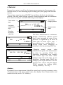
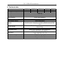
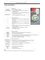
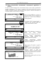
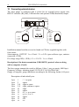
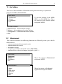
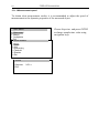
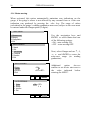
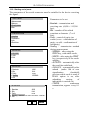
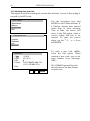
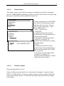
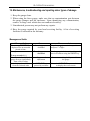
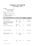
USER MANUAL TORQUE TESTER FSC Series File: 2015-10-05 FSC-141 FC012 GB FSB OPERATION MANUAL 2 Contents: 1. 2. 3. 3.1 3.2 Introduction __________________________________________________________________________________________________ 3 Basic Set ____________________________________________________________________________________________________ 3 Safety instructions _____________________________________________________________________________________________ 4 Main safety rules ______________________________________________________________________________________________ 4 Safety rules __________________________________________________________________________________________________ 5 3.2.1 Transport safety rules ___________________________________________________________________________________ 5 3.2.2 Safety rules during start-up and operation ___________________________________________________________________ 5 3.2.3 Safety rules during conservation___________________________________________________________________________ 6 4. Fast start ____________________________________________________________________________________________________ 7 5. Force meter general view _______________________________________________________________________________________ 8 6. Technical data ________________________________________________________________________________________________ 9 7. Keys and indicators ___________________________________________________________________________________________ 10 8. Preparing the force gauge for operation ___________________________________________________________________________ 11 9. Turning on the force gauge _____________________________________________________________________________________ 12 10. Accumulators exchange _______________________________________________________________________________________ 13 11. Description of measurement methods ____________________________________________________________________________ 14 11.1 Measuring actual and peak value of a pressure/pull force _____________________________________________________________ 14 11.2 Force characteristics measurement, measurement registration to memory _______________________________________________ 15 12. Connecting external devices ____________________________________________________________________________________ 16 13. User’s Menu ________________________________________________________________________________________________ 17 13.1 Measurement _______________________________________________________________________________________________ 17 13.1.1 Measurement speed ___________________________________________________________________________________ 18 13.1.2 Units _______________________________________________________________________________________________ 18 13.1.3 Auto-zeroing _________________________________________________________________________________________ 20 13.1.4 Comparison with threshold values MIN / OK / MAX ___________________________________________________________ 21 13.2 Memory _____________________________________________________________________________________________________ 22 13.2.1 Gathering results ______________________________________________________________________________________ 23 13.2.2 Presentation of collected measurements (Statistics) __________________________________________________________ 24 13.2.3 Save, read, erase memory (Statistics) _____________________________________________________________________ 24 13.3 Configuration ________________________________________________________________________________________________ 26 13.3.1 Setting serial ports ____________________________________________________________________________________ 27 13.3.2 Force meter calibration ________________________________________________________________________________ 28 13.3.3 Information __________________________________________________________________________________________ 29 13.3.4 Setting date and time __________________________________________________________________________________ 30 13.3.5 LCD settings _________________________________________________________________________________________ 31 13.3.6 Selecting the menu language ____________________________________________________________________________ 32 13.3.7 Printout settings ______________________________________________________________________________________ 33 13.3.8 Turning the sound ON/OFF when using the keypad (beep) _____________________________________________________ 34 13.3.9 Automatic power OFF (Auto-OFF) ________________________________________________________________________ 34 13.3.10 Monitoring the batteries’ charge level (Battery) ____________________________________________________________ 35 13.3.11 External input ______________________________________________________________________________________ 37 13.3.12 Firmware update ___________________________________________________________________________________ 37 13.3.13 Defaults __________________________________________________________________________________________ 38 14. Maintenance, troubleshooting and repairing minor types of damage _______________________________________________________ 39 15. FSC menu diagram _____________________________________________________________________________________________ 40 Declaration of Conformity ________________________________________________________________________________________ 43 FSC OPERATION MANUAL 3 1. Introduction The FSC series torque testers produced by AXIS Sp. z o.o. are designed for dynamic measuring of torque in manufacturing and quality control applications particularly to check/calibrate tension wrenches. Measurements results can be presented as graph or histogram and saved on microSD cards. The RS232C and USB interface allows the measurement results to be transmitted to a computer or a printer for further analysis or recording. 2. Basic Set 1. 2. 3. 4. 5. 6. 7. The basic set includes the following elements: Force gauge (meter + sensor), Accumulators NiMH 2700mAh – 4 pcs. Power supply unit ~230 V 50 Hz / =12 V; 1.25 A, Case Force gauge-computer cable CD containing an operation manual and software, Warranty. FSB OPERATION MANUAL 4 3. Safety instructions 3.1 Main safety rules Read carefully the safety instructions included below. Observe these instructions to avoid electrocution or damage to the force gauge itself or other devices connected to the force gauge. Repairs and any necessary adjustments may only be conducted by qualified personnel. Do not use the force gauge when any part of the enclosure has been removed. Do not use the force gauge in potentially explosive atmospheres. Do not use the force gauge in areas with a high humidity. In the case of suspected damage to the force gauge, turn off the gauge and do not use it until it is examined by a specialised servicing facility. FSC OPERATION MANUAL 3.2 5 Safety rules 3.2.1 Transport safety rules Force meter and included equipment should be transported from producer to receiver in original company box. To transport force meter during exploitation original producer case should be used. 3.2.2 Safety rules during start-up and operation Force meter with equipment supplied by producer is a safe device, what was achieved by application of fire protection and elimination of mechanical, chemical, explosive etc threads. In order to avoid danger we suggest to: Lp. Recommendation 1 Avoid contact with flood, water or other liquids due to high voltage 230V. 2 Damaged accumulators handle with care. Use rubber gloves and safety glasses if necessary. 3 The proper disposal of used force meter. 4 User manual training. 5 Periodic monitoring of connections Warnings ! ? ? Next control date: .......................... ........................... FSB OPERATION MANUAL 6 Specific recommendation: Risk of electric shock due to the use of ~230V 50Hz voltage via external feeder. It is unacceptable to spill the feeder or use it when the enclosure is damaged cause it may cause electric shock. In order to avoid leakage of electrolyte from accumulators immediate disposal of used accumulators from force meter is suggested. 3.2.3 Safety rules during conservation Force meter doesn’t need conservation except accumulators exchange when used – that happens when after full recharge the force meter working time is shorter more than 20% from the value suggested by producer. If the device seems to be damaged immediately stop operation. FSC OPERATION MANUAL 7 4. Fast start Prepare force meter to work by selecting proper measuring tip (force gauge with internal sensor) or after mounting proper working post (force gauge with external sensor). Turn on force meter by using ON/OFF key and leave the device in stationary position. That will enable zeroing, software version displaying and zero indication. Force meter is ready to work after following screen displays: Force meter type Accumulator charging status Type MAN Indication stabilization sign SLW AUT 0.00N∙m - Direction and force value bar Typ MAN SLW AUT 0.48N∙m - + Typ MAN PK→ LOCK SLW AUT 0.10N∙m ← 0,00 + Measurement result ˌ ˌ MIN MAX PEAK + 0,10 The force measurement is continuous. Display continuously indicates actual force value measured by meter. Force direction is signalized by an arrow in lower part of screen and a sign + (pressing force) or - (pulling force). Saving actual force indication to memory is done by pressing MEM key. Changing actual torque value indication into peak value measurement is done by pressing PEAK key. Indication stabilization sign changes into LOCK sign and force meter changes mode into peak value in one directions. Pressing again PEAK key changes peak torque direction: first for pressure force (PK) and after another PEAK pressing for pulling (PK), zeroing is done by 0 key. Attention: Dynamical forces measurement should be carried out by saving to memory series of measurements with given sample time, then display force characteristics and statistical results (rozdz. 14.3 Memory). FSB OPERATION MANUAL 8 5. Force meter general view FSC force meter: FSC... MAN type mark, accumulator charging indicator SLW AUT -- status indicators + measurement result force value and direction bar ON/OFF main keys UNIT/CLEAR BACKLIGHT navigation keys PEAK MEM O ENTER MENU PRINT FSC OPERATION MANUAL 9 6. Technical data Type Maximum force measured Reading graduation (d) Accuracy Measurement units Operating temperature Internal resolution Process speed Internal memory capacity Interface Assisting software Display Measurement options Power supply Accumulator working time Dimensions Weight FSC2 2Nm 0,001Nm FSC5 5Nm 0,002Nm FSC10 FSC100 10Nm 100Nm 0,01Nm 0,1Nm 0,1% F.S. Nm, N*cm, kgf*m, gf*m, lbf*in -10 ÷ 40°C FSC500 500Nm 1Nm 24 bits (16mln graduation) Regulated max 1000 measurements/s 1x6400 measurements RS-232C and USB, options: Bluetooth, WE trigger gate, WY transoptor MicroSD card slot: compatibility with SDSC (standard) cards and SDHC class 4 FM (time characteristics, statistic analysis, data archiving) LCD graphical Maximal value measurement, serial measurement, dynamic measurement (time diagrams) Ni-Mh batteries set 2700mAh + supply ~230V 50Hz / 12V 1,2A ~20h (~45h backlighting off) 215x100x40mm (meter) 430g (without batteries) FSB OPERATION MANUAL 10 7. Keys and indicators Main keys: ON/OFF - ON / OFF key (standby), UNIT/CLEAR - Change units / cancel selection or change a BACKLIGHT parameter value, - Press and hold – move to measurement menu (Statistics/Reset)/return - Turn on illumination (ECO mode), Navigation keys: - Move cursor up or increase the digit marked by - - ENTER MENU PEAK MEM PRINT 0 - the cursor, Move cursor down or decrease the digit marked by the cursor, Move to the next menu level or display the next option, Move to the previous menu level or display the previous option, Confirm the entered parameter or select a highlighted option. Function Keys: - Meter function menu (diagram menu - chapter 18), - Measure the maximum value, - Save the result to the memory, press and hold – save to memory menu, - Print result (transmission via RS-232C connector). - Force meter indications zeroing Status indicators: MIN/OK/MAX - Indications below MIN; in range MIN÷MAX; above MAX MAN/ACQ - Manual/automatic measurements mode /LOCK PK / PK SLW/FST AUT SD - Indicates that the weighing result has stabilised, - Direction of measured force, - Slow/fast measurement mode, - Autozeroing on - microSD card mounted Note: Numbers are entered using the navigation keys. First, the cursor is placed in the right digit position. FSC OPERATION MANUAL 11 8. Preparing the force gauge for operation If the force gauge has been transported from an area with low temperature to an area with a higher temperature, e.g. during winter, water may condensate on the gauge’s enclosure. In such a case, do not turn on the gauge’s power supply, as it may lead to damage to the gauge or improper operation. Before turning on the gauge, leave it for 1 hour to acclimatise. FSB OPERATION MANUAL 12 9. Turning on the force gauge AXIS Place the gauge in the operating position, e.g. horizontal position (by laying it on a table). Turn on the gauge by pressing the ON/OFF key. AXIS Sp. z o.o. ul. Kartuska 375B 80-125 Gdańsk When necessary, plug the gauge’s power supply unit to a ~230 V/50 Hz socket and connect the power supply unit’s plug to the gauge’s 12 V socket. ZEROING The gauge automatically tests the electronic subassemblies and then resets. During this operation, the gauge should remain stationary and its sensor should not be affected by any forces. FSC000 After the resetting has been successfully completed, the gauge indicates zero. Type MAN SLW AUT 0.000N∙m - - Unsuccessful resetting is signalled by an appropriate message. + Note: It is possible to accelerate the resetting process by pressing the MENU key, which will recall the results from the previous resetting. If the batteries are low, leave the gauge’s external power supply unit ON until they are fully recharged. The batteries’ charge level is signalled by an indicator in the upper section of the display. FSC OPERATION MANUAL 10. 13 Accumulators exchange If during exploitation time working time of fully charged accumulators shortens to 20% of the nominal value (under 4h), replace them with new ones. In order to exchange accumulators open the cover by tilting bracket and put new ones as indicated at the bottom of the housing (correct polarization). accumulators – 4pcs. cover cover bracket FSB OPERATION MANUAL 14 11. Description of measurement methods 11.1 Measuring actual and peak value of a pressure/pull force The zeroing process starts automatically after turning on the gauge or by pressing the 0 key. To perform the measurement, indicate the force direction using an arrow in the display’s lower bar section and “+” or “-”symbol. ZEROING ______ Type MAN SLW AUT 0.0000N∙m - + - Typ MAN PK→ LOCK SLW AUT 0.10 N∙m - ˌ ˌ + MIN MAX ↓ 0,00 0,10 To change the measurement from the actual value (continuous measurement) to the maximum value (peak measurement), use the PEAK key – stabilization indicator is replaced by LOCK indicator. Pressing again PEAK button will change direction of the measured force (PK→, PK←), zeroing by using 0 key. When measuring maximum value, at the bottom of the screen appears a bar showing actual force value and maximum force value for other force direction if it was measured before otherwise 0,00 value will indicate. FSC OPERATION MANUAL 15 11.2 Force characteristics measurement, measurement registration to memory In order to enable changing force measurement and to create results visualizations (graphs or histograms), force gauge is equipped with actual results buffer memory (RAM), EEPROM memory and microSD card (option). Detailed description of available options can be found in 14 chapter. NORMAL MEASUREMENT AUT 1.00 N∙m - + MEM After pressing MEM key results are stored in buffer memory. Quantity of result in a 1 serie is set in Memory/ Setting/Quantity . If indicator MAN (manual mode) is displayed, after pressing MEM key single measurement is stored. SAMPLE 001 - + - NORMAL MEASUREMENT ACQ AUT 1.00 N∙m - + - MEM SAMPLE 001/100 ACQ AUT 1.00 N∙m - + - 001: 1.00N 0,100s F When ACQ indication is turned on, MEM key starts storing measurements in equal time intervals. During storing measurements successive sample numbers are displayed and total quantity. During measurement storing, numbers of samples and total sum of samples are displayed. After storing all samples a graph is displayed. ENTER – returns to force indications, MEM – Statistics results displaying. Statistics option is used for obligatory storing or deleting actual results (next measurement is possible only after deleting). UNIT/CLEAR enables quick exit from t Statistics option. FSB OPERATION MANUAL 16 12. Connecting external devices The force gauge is equipped with a socket for an external power supply unit, RS232C interface (RJ joint), USB interface and optional THR (thresholds) output. OUTPUT (option) FEEDER RS232C IN/OUT 1 - WE(-) 2 - GND 3 - MAX 4 - ZERO 5 - MIN 6 - WE(+) 1 - RxD 2 - masa 3 - TxD 4 - NC Installation manual and drivers can be found on CD disc supplied together with force meter. Joint ampacity OUTPUT: I max=25mA / U nom=24V (open collector type, emitters connected– GND). IN voltage range WE(+)/WE(-): U in=12-18V / I in max=50mA Description of the data transmission (USB, RS232) protocol when working with a computer (LonG): The force gauge transmit the result as follows (8 bits, 1 stop, no parity, 4800 bps): ComputerGauge: initiating signal S I CR LF (53 h 49 h 0Dh 0 Ah), GaugeComputer: gauge indication according to the following format (16 bytes): Description of individual bytes: byte byte byte byte byte byte byte byte byte byte byte 1 2 34 5÷9 10 11 12 13 14 15 16 - “-“ or space - space - digit or space - digit, comma or space - digit - space - k, l, c, p or space - g, b, t, c or % - space - CR - LF FB OPERATION MANUAL 17 13. User’s Menu The User’s Menu includes all functions and options necessary to operate the gauge or extend its functionalities. USER MENU 1. 2. 3. 4. Measurement Memory Configuration Exit To use the options of the USER’s MENU, use the MENU key. Move the cursor to the desired option and press ENTER. The menu includes: 1. Measurement – measurement settings, 2. Memory – data readout and saving options, 3. Configuration – calibration and other options, 4. Exit. 13.1 Measurement This selection includes the following functions to effectively assist you with the measurement: - measurement speed in automatic mode, - measurement unit choice, - automatic zeroing, - comparison with two threshold values (MIN / MAX), - measured force direction change (accepted as plus + ) USER MENU 1. Measurement 2. Memory 3. Configuration 4. Exit Move the cursor to Measurement and press ENTER. MEASUREMENT 1. Speed 2. Unit 3. Auto-zeroing 4. Threshold 5. Direction 6. Exit Move the cursor to the desired application and press ENTER. OPERATION MANUAL 18 13.1.1 Measurement speed To obtain clear measurement results, it is recommended to adjust the speed of measurement to the dynamic properties of the measured object. USER MENU 1. 2. 3. 4. Measurement Memory Configuration Exit MEASUREMENT 1. Speed 2. Unit 3. Auto-zeroing 4. Threshold 5. Direction 6. Exit SPEED 1. Smp.time: 2. Exit 0.001 s Choose Smp.time and press ENTER to change sample time value using navigation keys. FB OPERATION MANUAL 19 13.1.2 Units Torque units: - newton-metre (N∙m) – torque basic unit, - newton-centimetre (N∙cm): 1N∙m = 100 N∙cm, - kilogram-metre (kg∙fm): 1N∙m = 0,1020 kgf∙m, - gram-force-metre (gf∙m) : 1N∙m= 1020 gf∙m, - pound-force-inch (lbf∙in): 1N∙m= 8.85 lbf∙in. To change the units, press the UNIT/CLEAR or MENU key several times. USER MENU 1.Measurement 2.Memory 3.Configuration 4.Exit MEASUREMENT Press the MENU key, move the cursor to Unit and press ENTER. 1. Speed 2. Unit 3. Auto-zeroing 4. Threshold 5. Direction UNIT 6. Exit [N∙m] [N∙cm] [kg∙fm] [gf∙m] [lbf∙in] out Move the cursor to the desired unit and press ENTER. ENTER During mass measurement the force meter measures gravitation force and converts it to mass. Calculating force and mass unit is depended to gravitation force of the place of measurement. Default value is the producer gravitation value g = 9,81415m/s2 . During very precise mass measurements (0,1% of range) it is crucial to inscribe proper gravitation value of the measurement place (Calibration options). OPERATION MANUAL 20 13.1.3 Auto-zeroing When activated, this option automatically maintains zero indications on the gauge, if the gauge’s sensor is not affected by any external force or if the zero indication was produced by pressing the 0 key. The range of values (calculated in the gauge’s reading graduation near zero) subject to the reset must be entered under the Range option (2 digits). USER MENU 1.Measurement 2.Memory 3.Configuration 4.Exit Use the navigation keys and ENTER to select Status and one of the following options: - ON – auto-zeroing ON, - OFF – auto-zeroing OFF. MEASUREMENT 1. Speed 2. Unit 3. Auto-zeroing 4. Threshold 5. Direction 6. Exit Next, select Range and use , , , and ENTER to enter the auto-reset range (in reading graduation). AUTO-ZEROING 1. Status 2. Range 3. Art.zero 3. Exit <ON> 2d <OFF><SET> ENTER AUTO-ZEROING 1. Status 2. Range 3. Art.zero 4. Exit <ON> <OFF> 2 d ENTER Additional option Art.zero enables to set device start zero to the value indicated before entering the MENU . FB OPERATION MANUAL 21 13.1.4 Comparison with threshold values MIN / OK / MAX This selection includes the following functions to effectively assist you with the measurement: - memory operations and data analysis, - comparison with two threshold values (MIN / MAX). USER MENU 1.Measurement 2.Memory 3.Configuration 4.Exit Move the cursor to Applications and press ENTER. MEASUREMENT 1. Speed 2. Unit 3. Auto-zeroing 4. Threshold 5. Direction 6. Exit Move the cursor to Threshold and press ENTER. THRESHOLD 1. 2. 3. 4. Status MIN MAX ZERO 4. Output 5. Exit <ON> <OFF> 1.000kg 2.000kg 0.000kg MODE1 ENTER Type OK MAN SLW AUT Activate the comparison by setting Status to ON: - enter the MIN value – lower threshold, - enter the MAX value – upper threshold, - enter ZERO – zero signalling threshold. Select the option for OUTPUT and sound signalling (Buzzer): - MODE1 – short signal upon exceeding MIN, long signal upon exceeding MAX, - MODE2 – interrupted signal below MIN, above MAX – continuous signal, for OK – no signal. 1.00 N∙m - + Exit the menu, start the measurement and observe the MIN, OK and MAX indicators on the gauge’s display. OPERATION MANUAL 22 13.2 Memory During measurements in automatic mode results are saved in volatile memory (RAM – erasing data after supply off). Saving, readout, erasing data (single series of measurements) in EEPROM and reseting volatile memory (RAM) is done by options in lower part of Statistics function screen. It is possible to view results on force meter (chart, histogram, table). Using microSD card enables to save and later readout of many series of measurements in chosen file. It is possible to write custom names (inscribed by user) of folders and files. MicroSD memory card can be put out from force meter in order to edit files on computer (.txt) and import them to other specialized software. In order to do that use microSD/SD adapter and readout files on computer. Put microSD card into force meter using pushing element. The card plunges completely into housing and locks. SD or SDH (SDHC) icon appears on display. Push the card in order to unlock it. microSD slot pushing element microSD card Memory option enables to: - select gathering results mode, - exposure of gathered measurements, storing , readout, deleting memory (Statistics), - exit. FB OPERATION MANUAL 23 13.2.1 Gathering results USER MENU Move the cursor to Memory and press ENTER. 1.Measurement 2.Memory 3.Configuration 4.Exit MEMORY Move the cursor to Settings and press ENTER. 1. Statistics 2. Settings 3. Exit Setting the mode for collecting data: - MANUAL – each time after MEM is pressed, SETTINGS 1. 2. 3. 4. 5. 6. 7. Mode Quantity Smp.time Record Autosave SD card Exit <MANUAL><AUTO> 10 0.1sek R/EEPROM ENTER - AUTO – automatically at specified intervals. Insert quantity of samples (max 100) After choosing Manual mode user should specify whether he wants to save the time of each measurement (R/D&T option). In Autosave option user can choose the place of autosaving results (EEPROM or SDCARD). After selecting AUTO, enter the number of samples (max 100) and sampling time (0.199.9 s. or 0,02525s depending on speed of measurement in Configuration). To start the collection of measurements, exit the menu and press MEM several times or press MEM for automatic save. When in the automatic save mode, press and hold MEM to go to the data save menu OPERATION MANUAL 24 13.2.2 Presentation of collected measurements (Statistics) The Statistics option allows for the following forms of presentation of the collected data: <PRINT> – transmission to a printer, <HISTOGRAM> – bar graph, <GRAPH> – graph with a time axis. USER MENU 1.Measurement 2.Memory 3.Configuration 4.Exit Move the cursor to Memory and press ENTER. MEMORY 1. Statistics 2. Settings 3. Exit Statistics Ilość Suma Średnia MAX MIN MAX-MIN Odchyl. Odch. % Prb0001 Prb0002 ..... Prb100 Move the cursor to Statistics and press ENTER. 100 2418.85N 24.19N 144.90N 1.40N 143.50N 40.805N 168.70% 2.95N 5.75N Select one of the options from the lower menu bar: - PRINT – transmission to a printer, - HISTOGRAM – bar graph, - GRAPH – graph with a time axis. ... - RESET – erases the entire memory, - DELETE – deletes a selected memory file. 1.40N <PRINT><HISTOGRAM><GRAPH><SAVE><READ> <RESET><DELETE><EXIT> HISTOGRAM Indicators <L... =..> provide the size of the bar indicated by the arrow. To move the arrow (scroll the graph), use the and keys. MIN MAX <L01 = 8> ENTER FB OPERATION MANUAL 25 13.2.3 Save, read, erase memory (Statistics) The Statistics option allows for the following: < SAVE > – saves the data currently presented, < READ > – reads a file from the memory, < RESET > – erases the data currently presented, < DELETE> – delete selected data file. These options show up in the bottom bar (change option using or keys). USER MENU In order to choose saving location move the cursor to Memory and press ENTER. 1.Measurement 2.Memory 3.Configuration 4.Exit Move the cursor to Settings and press ENTER. Choose Mode. In Auto mode results are saved to RAM memory. In Manual mode saving to RAM, EEPROM or microSD card is possible. MEMORY 1. Statistics 2. Settings 3. Exit SETTINGS 8. 9. 10. 11. 12. 13. 14. Mode <MANUAL><AUTO> Quantity 10 Smp.time 0.1sek Record R/Autosave <OFF><EEPROM><SDCARD> SD card Exit ENTER SD CARD 1. Folder 2. FILE 3. Exit FB_DATA data001.txt ENTER In order to save file on SD card set Autosave to SDCARD and move cursor to SD card position and press ENTER. The following options will appear: - Folder – enables to inscribe the name of the folder on microSD card, - FILE – enables to inscribe file name on microSD card, - EXIT – exit. OPERATION MANUAL 26 13.3 Configuration This selection includes all options for setting the gauge’s modes of operation. USER MENU 1.Measurement 2.Memory 3.Configuration 4.Exit Move the cursor to Configuration and press ENTER. CONFIGURATION 1. Interface 2. Calibration 3. Info 4. Time&date 5. LCD settings 6. Language 7. Printout 8. Keyboard 9. Auto-OFF 10. Battery 11. External input 12. Firmware Update 13. Defaults 14. Exit Move the cursor to the desired option and press ENTER. ENTER FB OPERATION MANUAL 27 13.3.1 Setting serial ports The parameters of the serial connector must be suitable for the device receiving the signal. USER MENU Parameters to be set: 1.Measurement 2.Memory 3.Configuration 4.Exit CONFIGURATION 1.Interface 2.Calibration 3.Info 4.Date/time … INTERFACE 1. RS-232C 2. USB 3. Exit INTERFACE 1. Baudrate 2. Bits 3. Parity 4. Sending 5. Exit 4800 8-bit none NORMAL INTERFACE 1. Baudrate 4800 2. Bits 8-bit 3. Parity none 4. Sending <NORMAL><NO STB><AUTOSTB> <CONTIN.> 5. Exit ENTER ENTER - Baudrate – transmission and receiving rate (4,800 115,200 bps), - Bits – number of bits which constitute a character (7 or 8 bits), - Parity – control of parity (no control, even – confirmation of parity, or odd – confirmation of odd parity), - Sending – transmission method during measurement: - NORMAL – after using the PRINT key, with stable result, - NOSTB – after using the PRINT key, irrespectively of the result stability, - AUTOSTB – automatically after the result has stabilised, - REMOVE – automatically after unload (under 10d or zero signalization threshold) previous stable result is send; if PEAK option is on, after unloading zeroing of indications is carried out, - CONTIN. – continuous transmission, approx. every 0.1 s. OPERATION MANUAL 28 When the force meter is equipped with two serial interfaces (RS232C and USB) in submenu Interface two options are available RS232C and USB. After choosing proper port all settings are done the same way as above. 13.3.2 Force meter calibration Entrance to calibration is secured by PIN password. Calibration should be executed by AXIS personnel. Reset the device without load using the 0 key. USER MENU 1.Measurement 2.Memory 3.Configuration 4.Exit ENTER CALIBRATION 1. Calibration - START 2. Calibration mode 3. Torque 4. Gravitational acc. 5. Arm’s length 6. Correction 7. Load cell 8. Factory calibration 9. PIN 10. . Exit Nm 2.00Nm 9,81416m/s2 0,500m ENTER CALIBRATION 1. Calibration - START 2. Calibration mode 3. Torque 4. Gravitational acc. 5. Arm’s length 6. Correction 7. Load cell 11. Factory calibration 12. PIN 13. . Exit Nm 2.00Nm 9,81416m/s2 0,500m ENTER Use the navigation keys and ENTER to select Configuration and then Calibration. Depending on the arm choose Torque and Arm’s length options.. The <...> option allows for entering any value. Enter the gravitational acceleration to correctly convert mass (kg) into force (N). If the exact “g” value is not known, enter the parameters of the geographical location (latitude and above mean sea level). The “g” value will be calculated automatically. Apply the standard of mass to the gauge. Use the navigation keys and ENTER to select Calibration and wait until the calibration process is completed. Correction option enables changing torque indications with inscribed value. Factory calibration option enables to return to factory settings. FB OPERATION MANUAL 29 13.3.3 Information Option gives basic information about the device. USER MENU 1.Measurement 2.Memory 3.Configuration 4.Exit CONFIGURATION 1.Interface 2.Calibration 3.Info 4.Date/time … INFO MODEL MAX SOFT DATE S/N Card AXIS Sp. z o.o. Available information: - force meter type (Model) - measurement range (MAX) - internal software version (SOFT) - serial number (S/N) - production date (DATE) - memory card type (Card) - producer name OPERATION MANUAL 30 13.3.4 Setting date and time This option is used for entering the current date and time. Access to this setting is secured by the PIN code. USER MENU Use the navigation keys and ENTER to select Date and time. If a PIN has already been entered (other than 0), after selecting Time or Date, the cursor will move to the PIN option, where a correct 4-digit PIN has to be entered. To enter the correct digits, use the , , , keys and ENTER. 1.Measurement 2.Memory 3.Configuration 4.Exit CONFIGURATION 1.Interface 2.Calibration 3.Info 4.Date/time … TIME&DATE 1. Time 2. Date 3. PIN 4. Format 10:00:00 2011-01-11 0 <YYYY-MM-DD><MM- DDYYYY> <DD-MM-YYYY> 5. Exit ENTER To enter a new code (NEW), select the PIN option. When entering a new code, type in the same number twice (message: REP.). The FORMAT option allows for the selection of the date format on print-outs. FB OPERATION MANUAL 31 13.3.5 LCD settings This option adjusts the gauge’s display to external lighting conditions. USER MENU 1.Measurement 2.Memory 3.Configuration 4.Exit Use the navigation keys and ENTER to select LCD settings. Next, use , and ENTER to set the contrast at which the display is best legible. CONFIGURATION 1.Measure speed 2.Auto-zeroing 3.Printout 4.Interface 5.LCD settings SETTINGS 1. Contrast 2. Backlig. 3. Direct. 4. LCD time 5. Exit <ON> OFF ENTER SETTINGS 1. Contrast < > 2. Backlig. <ON><OFF><ECO><BAT> 3. Direct. 4. LCD time OFF 5. Exit ENTER SETTINGS 1. Contrast 2. Backlig. 3. Direct. 4. LCD time 5. Exit < > <ECO> <AUTO><UP><DOWN> OFF ENTER When setting Backlig. (backlighting), select one of the following options: - OFF – backlighting OFF, - ON – backlighting continuously ON, - ECO – to backlight, use the BACKLIGHT key, - BAT – backlighting is turned off after 30 seconds to save the batteries. The DIRECT. (direction) option is used for selecting the display’s direction: - AUTO – automatic rotation of the displayed image, - UP – standard direction, - DOWN – inverted image. The LCD TIME option displays the date and time during measurement in the display’s upper bar. OPERATION MANUAL 32 13.3.6 Selecting the menu language Three menu languages are available: <PL> – Polish, <ENG> – English, <DE> – German, <ESP> - Spanish. USER MENU Use the navigation keys and ENTER to select Language. To select one of the available menu languages, use the , keys and ENTER. 1.Measurement 2.Memory 3.Configuration 4.Exit CONFIGURATION ... 4. RS-232C settings 5. LCD settings 6. Language 7. Date and time 8. Auto-OFF To enter a new code (NEW), select the PIN option. When entering a new code, type in the same number twice (message: REP.). LANGUAGE 1. Language 2. Exit <PL><ENG><DE><ESP> ENTER FB OPERATION MANUAL 33 13.3.7 Printout settings According to the requirements of GLP procedures, it is possible to use an external printer to produce print-outs from the gauge including text information. USER MENU Use the navigation keys and ENTER to select Printout and the suitable print components. 1.Measurement 2.Memory 3.Configuration 4.Exit CONFIGURATION 5. LCD settings 6. Language 7. Printout 4. Interface 5. LCD settings ID1, ID2, ID2 – text strings (up to 20 characters) forming the lines of the print-out, entered using the gauge’s navigation keys (starting from ). PRINTOUT Heading Date Time ID1> ID2> ID3> Number Signature Exit ENTER PRINTOUT Heading Date Time ABCD ID2 ID3 ENTER To enter the characters, select ID using ENTER and press . The characters are entered using the navigation keys and . To move the cursor to the consecutive positions, use and . To confirm the entered string, press ENTER. To delete a character, enter space OPERATION MANUAL 34 13.3.8 Turning the sound ON/OFF when using the keypad (beep) This options turns ON or OFF the sound signalling that a key on the keypad has been pressed. When the sound is turned on, the user usually does not apply excessive force when pushing the keys. USER MENU Use the navigation keys and ENTER to select Keypad and Buzzer, and one of the following options: - ON – sound ON, - OFF – sound OFF. 1.Measurement 2.Memory 3.Configuration 4.Exit CONFIGURATION 3. Printout 4. Interface 5. LCD settings 6. Language 6. Time&date 7. Keyboard KEYBOARD 1. BEEP 2. Exit <ON><OFF> ENTER KEYBOARD 1. BEEP 2. Exit <ON> ENTER FB OPERATION MANUAL 35 13.3.9 Automatic power OFF (Auto-OFF) This option allows for an automatic cut-off of the gauge’s power supply to save the battery’s energy. USER MENU 1.Measurement 2.Memory 3.Configuration 4.Exit Use the navigation keys and ENTER to select Auto-OFF and Status, and one of the following options: - ON – the power is turned off after 5 minutes, the indications remain unchanged, - BAT – the power is turned off when the battery is low, - OFF – the power is not turned off. CONFIGURATION 1.Interface 2.Calibration 3.Info 4.Time&date 5.LCD settings 6.Language 7.Printout 8.Keyboard 9.Auto-OFF 10.Battery 11.External input 12.Firmware Update 13.Defaults 14.Exit AUTO-OFF 1. Status 2. Exit OFF ENTER AUTO-OFF 1. Status: 2. Exit <OFF> <BAT> <ON> ENTER OPERATION MANUAL 36 13.3.10 Monitoring the batteries’ charge level (Battery) This option is used for reading the charge level of the batteries and allows for the charging to be turned off to protect ordinary batteries, if such batteries are used instead of rechargeable batteries. Charging ordinary batteries used instead of rechargeable batteries may lead to major damage to the gauge. USER MENU 1.Measurement 2.Memory 3.Configuration 4.Exit Use the navigation keys and ENTER to select Battery and Charging, and one of the following options: - ON – charging ON, - OFF – charging OFF. CONFIGURATION 1.Interface 2.Calibration 3.Info 4.Time&date 5.LCD settings 6.Language 7.Printout 8.Keyboard 9.Auto-OFF 10.Battery 11.External input 12.Firmware Update BATTERY 13.Defaults 14.Exit 1. Charging 2. Level 3. Exit OFF 80% ENTER BATTERY 1. Charging 2. Level 3. Exit <OFF> <ON> 80% ENTER FB OPERATION MANUAL 13.3.11 37 External input This option can be used when force gauge is applied in any kind of automated process. THRESHOLD (optionally) output is used for this function so when using this option threshold function should be turned off. USER MENU 1.Measurement 2.Memory 3.Configuration 4.Exit CONFIGURATION ... 8. Keyboard 9. Auto-OFF 10. Battery 11. External input EXTERNAL INPUT 1. Status : 2. Exit 13.3.12 <OFF><TRIGGER><GATE> Using navigation keys and ENTER key choose Configuration option and then External input. Choose Status option and using ← and → keys choose from: - OFF – function off, - TRIGGER: a) manual measurement mode – measurement storing initiated by a single external signal, b) automatic measurement mode – storing of set quantity of measurements initiated by a single external signal, - GATE: a) manual measurement mode measurement storing initiated by a single external signal while MEM key is pressed, b) automatic measurement mode – storing of set quantity of measurements initiated by external signal state time window. Firmware update Option designated for service Option enables program update by connecting force gauge to computer using RS232 or USB interface. Firmware update message on force gauge’s display is connected with this option. To delete this message, disconnect the force gauge from supply. OPERATION MANUAL 38 13.3.13 Defaults This option restores factory settings (default settings) for all options. USER MENU 1.Measurement 2.Memory 3.Configuration 4.Exit Use the navigation keys and ENTER to select Reset settings and the option YES. As a result of restoring factory settings, the gauge will reset and start continuous measurement. CONFIGURATION ... 7. Date and time 8. Auto-OFF 9. Battery 10. Defaults DEFAULTS Restore default settings? NO YES ENTER FB OPERATION MANUAL 39 14. Maintenance, troubleshooting and repairing minor types of damage 1. Keep the gauge clean. 2. When using the force gauge, make sure that no contamination gets between the gauge plunger and the enclosure. Upon identifying any contamination, remove it using a tool which does not conduct electricity. 3. Unauthorised person may not perform any repairs. 4. Have the gauge repaired by your local servicing facility. A list of servicing facilities is enclosed in the warranty. Messages and faults: Message/fault Cause The message RESETTING is displayed for an extended period of time. Message: Resetting process disturbed AD range exceeded (+/-) The values indicated by the gauge diverge significantly from correct values Units displayed are different from the selected units Resetting process disturbed Recommendation Keep the gauge in motionless position and press T(0) Put the gauge in horizontal position and turn it off and on using the ON/OFF key. Gauge out of adjustment Contact a servicing facility to calibrate the gauge UNIT/CLEAR key pressed by accident Press the UNIT/CLEAR key several times to display the correct units OPERATION MANUAL 40 15. FSC menu diagram Menu Measurement Speed Smp. time Exit Unit newton-metre [N•m] newton-centimetre [N•cm] kilogram-metre [kg•fm] gram-force-metre [gf•m] pound-force-metre [lbf•in] Auto-zeroing Status Range Art.zero Exit Threshold Status <ON><OFF> MIN MAX ZERO Output <MODE1-impulses> <MODE2-states> Buzzer <OFF> <ON> Exit Status <NORMAL><REVERSE> Exit AutoMEM <OFF><ON> (automatic PEAK indication storing) Exit Direction PEAK Exit Memory Statistics Settings Samples Total Average MAX MIN MAX-MIN St.dev. Rel.dev. Smp0001 Smp0002 ... Mode Quantity Trigger Delay at Time del. Record Autosave SD card Exit <ON><OFF> < .. d> <OFF> <SET> Direct acces keys: MEM CLEAR <MANUAL> <AUTO> <trigg.><start> <R/ - ><R/D&T(tylko tryb RĘCZNY)> <OFF><EEPROM><SDCARD> Folder File Exit FB OPERATION MANUAL Configuration Interface Calibration Info RS-232C Baudrate <4 800-115 200> Bits <7>< 8-bit> Parity <none><even><odd> Sending <NORMAL><NO STB><AUTOSTB> <CONTIN.> Exit USB Exit j.w. Mode Force/Load g = Geogr. location Correction Load-cell Factory calibr. PIN Exit <N/kN> <kgf> <lbf> <ozf> <kg> <lb> <oz> <full range> < ... - inscribed value> <gravitional acceleration in measurement place> <0,000> <MAX=...><SENS=...> (inscribing sensor parameters) <NO><YES> Time&date Contrast Backlig. <ON><OFF><ECO><BAT> Direct. <AUTO><UP><DOMN> Time LCD <OFF><ON> Exit Time Date PIN 1234 12/24 <12H> <24H> Form. <YYYY-MM-DD><MM-DD-YYYY><DD-MM-YYYY>> Exit Language <PL><ENG><DE><ESP> Printout Header Date Time ID1> ID2> edition after pressing ID3> Measurem. No Signature Exit LCD settings 41 OPERATION MANUAL 42 Keyboard Beep <ON> <OFF> Exit Auto-OFF Status: <OFF> <BAT> <ON> Exit Battery Charging <OFF> <ON> Level [%] Exit External input Status <TRIGGER> <GATE> Wyjście Firmware update (service option) Defaults Exit Exit <NO><YES> FB OPERATION MANUAL 43 Declaration of Conformity We: AXIS Spółka z o.o. 80-125 Gdańsk, ul.Kartuska 375B confirm with all responsibility that force gauges: FSC2, FSC5, FSC10 marked with CE mark comply with the following: 1. Directive 2004/108/EWG (electromagnetic compatibility) and harmonized norms: PN-EN 61000-4-3+A1:2008+A2:2011 PN-EN 61000-6-3:2008+A1:2011 PN-EN 55011:2007+A2:2007 Additional information: - Conformity evaluation were carried out by Laboratorium Badawcze Oddziału Instytutu Elektrotechniki in Gdańsk, accredited by PCA (AB007), examination report nr 109/LMC738/2009 from 28.09.2009 r.. Gdańsk, 14-11-2014 r. Per pro Director of AXIS Sp. z o.o.: Production Manager Jan Kończak _________________ Signature